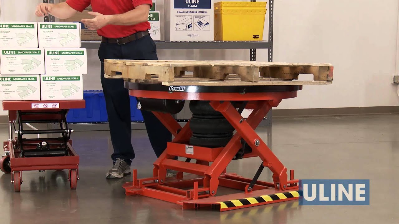
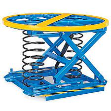
ULINE Spring-Loaded Pallet Positioner
TECHNICAL DATA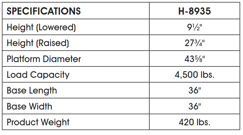
SAFETY
SAFETYMachine should be installed, operated and maintained by trained and/or qualified personnel only.LABELINGMachine has labeling to indicate potential hazards it may pose when operating and/or maintaining. All labels must be legible. If any label is missing, damaged or otherwise illegible, contact the manufacturer for replacement labels.
SIGNAL WORDS
- DANGER – indicates a hazardous situation that, if not avoided, will result in death or serious injury.
- WARNING – indicates a hazardous situation that, if not avoided, could result in death or serious injury.
- CAUTION – indicates a hazardous situation that, if not avoided, will result in a minor or moderate injury.
- NOTICE – indicates information considered important, but not hazardous (e.g., messages relating to property damage).
INSTRUCTIONS
RAISING THE PLATFORM
- Remove the rotating ring by lifting it off platform. Set ring aside.
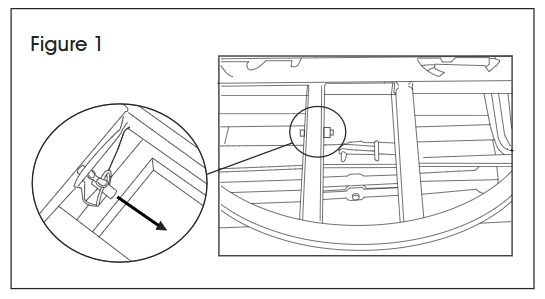
- Locate the damper and pin near middle of base. Remove pin to release damper. (See Figure 1)
- With another person, lift the platform until roller pins meet the latch stops located on each side of platform.
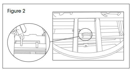
- Lift latch stops. Keeping the latch stops lifted, continue lifting the platform until it is fully raised. (See Figure 2)
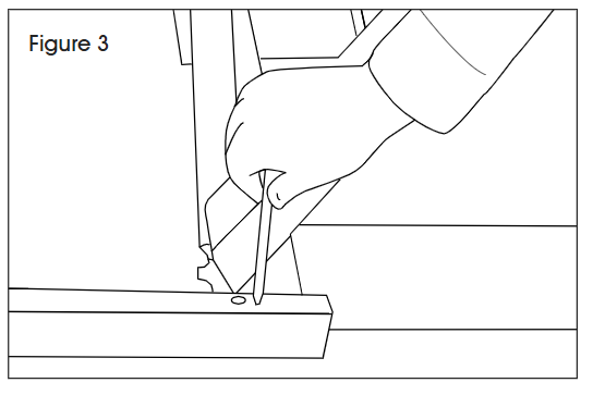
- While keeping the platform raised, place the pin from step 2 into the hole in the roller track closest to the hinge. (See Figure 3)
INSTALLING ORANGE SPRING
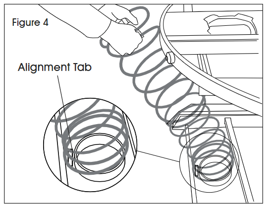
- On the side of the base with roller tracks, insert the orange spring into the spring pocket. Ensure alignment tab is inside the spring. (See Figure 4)
- Firmly holding the spring a few coils down from the top, compress the spring and slide it into the upper spring pocket. Ensure the spring is fully seated in both the upper and lower pockets.WARNING! Do not hold the top coil of the spring. Doing so may cause hands and fingers to be crushed when sliding in the spring.
- Remove the pin from its current location in the roller track. The platform should now remain elevated.
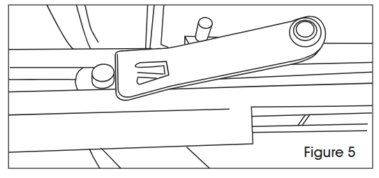
- Press down on platform until the two latch stops fall back into place behind roller pins. (See Figure 5)
- Lift damper back into place and secure with pin.
- Secure spring with the safety lock.
INSTALLING ADDITIONAL SPRINGS
- Additional springs can be installed through the bayonet openings as needed. (See Figure 6)
- Secure the bayonets by placing them into the openings and turning clockwise. Secure the bayonets with the safety lock.
- For spring configurations, see the Spring Selection chart on page 3.

SPRING SELECTION
- Spring configurations are based on the specific load weight and height range.
- When the load weight and/or height of the skid changes, a different spring configuration may be needed.
- Refer to the Spring Selection Chart below to determine which springs are required for application.
SPRING SELECTION CHART
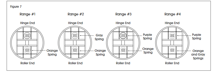
SPRING LOCATION
- The location of the springs will vary based on the range used for application.
- The orange spring will always be located on the roller track end of the base. Additional springs will be located as indicated below based on the range being used. (See Figure 7)
[xyz-ips snippet=”download-snippet”]