![]()

In-Wall Smart Switch
![]() Z-Wave® certified wireless lighting controlAll brand names shown are trademarks of their respective owners MADE IN CHINA/HECHO EN CHINADistributed by Jasco Products Company LLC, 10 E. Memorial Rd., Oklahoma City, OK 73114. ©JASCO 2020 | ZW4009 | 39354 | 09/02/20 v3
Z-Wave® certified wireless lighting controlAll brand names shown are trademarks of their respective owners MADE IN CHINA/HECHO EN CHINADistributed by Jasco Products Company LLC, 10 E. Memorial Rd., Oklahoma City, OK 73114. ©JASCO 2020 | ZW4009 | 39354 | 09/02/20 v3
39354 ZW4009
Thank you for your purchase!
Instructions made easy https://byjasco.com/39354iRead instructions or watch the easy-to-follow videos.Scan code or visit byjasco.com/39354i https://byjasco.com/39354iRead instructions or watch the easy-to-follow videos.Scan code or visit byjasco.com/39354i |
Exclusive deals https://byjasco.com/dealsFor deals, to register your purchase and to tell us how we’re doing, simply scan the code or visit byjasco.com/deals https://byjasco.com/dealsFor deals, to register your purchase and to tell us how we’re doing, simply scan the code or visit byjasco.com/deals |
For additional UltraPro products, visit our website. www.ezzwave.com
![]() Like our product? Leave a review on amazon.com
Like our product? Leave a review on amazon.com![]() Having problems? Let us know how we can help. 1-800-654-8483 between 7 AM-8 PM, M-F, Central Time.
Having problems? Let us know how we can help. 1-800-654-8483 between 7 AM-8 PM, M-F, Central Time.
FEATURES
- Can be added in multiple groups and scenes
- May be used in the single-pole installation or with up to four add-on switches (model 39356) in 3-way wiring configurations
- Z-Wave certified for simple pairing and integrated home automation
- Screw terminal installation — requires wiring connections for line (hot), load, neutral, and ground. Traveler wire required for 3-way or 4-way installation
- This Z-Wave device has advanced features that allow you to customize your experience. For a complete list of adjustable configurations, visit www.ezzwave.com
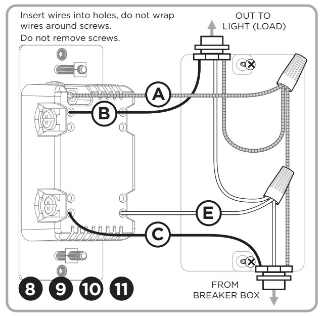
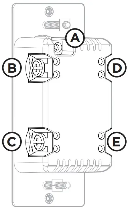 A. Ground (Green/Bare)B. Line or Load (Black)C. Line or Load (Black)D. Traveler (Red/Other)E. Neutral (White) A. Ground (Green/Bare)B. Line or Load (Black)C. Line or Load (Black)D. Traveler (Red/Other)E. Neutral (White) |
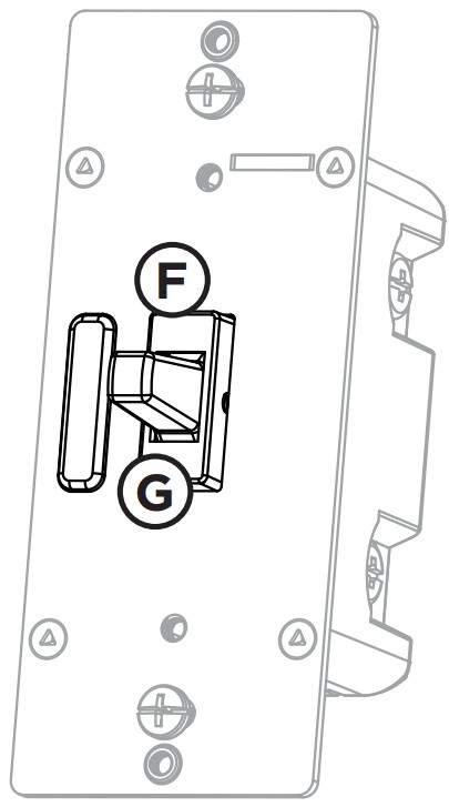
F. Up — press & release to turn the switch ONG. Down — press & release to turn the switch OFF |
INSTALLATION
WARNING — SHOCK HAZARDTurn OFF the power to the branch circuit for the switch and lighting fixture at the service panel. All wiring connections must be made with the POWER OFF to avoid personal injury and/or damage to the switch. This device is intended for installation in accordance with the National Electric Code and local regulations in the United States or the Canadian Electrical Code and local regulations in Canada. If you are unsure or uncomfortable about performing this installation, consult a qualified electrician.
MULTI-SWITCH WIRINGAdd-on switch model 39356 is required for multi-switch installations. For more information on multi-switch installations, refer to the add-on switch manually.SINGLE-SWITCH WIRING
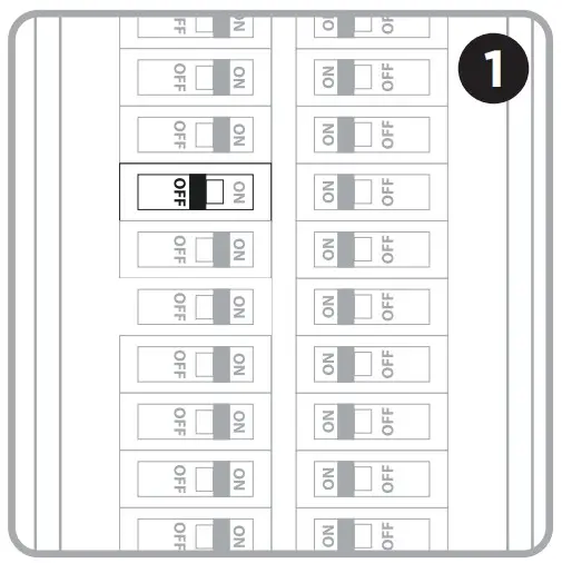
- Shut off power to the circuit at the circuit breaker or fuse box.IMPORTANT! Verify power is OFF to the switch box before continuing.
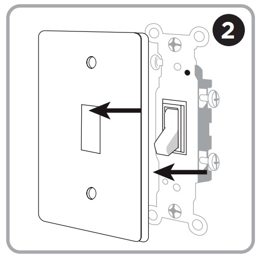
- Remove wallplate.
- Remove the switch mounting screws.

- Carefully remove the switch from the switch box. DONOT disconnect the wires.
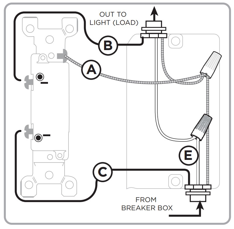
- There are up to five screw terminals on the switch; these are marked:A. GROUND — Green/BareB. LINE OR LOAD — Black (connected to power or lighting)C. LINE OR LOAD — Black (connected to power or lighting)D. TRAVELER — ed/Other (only in 3-way installations)E. NEUTRAL — White Match these screw terminals to the wires connected to the existing switch.
- Disconnect the wires from the existing switch. Label wires according to the previous terminal connection.OBSERVE IMPORTANT WIRING INFORMATIONIMPORTANT! This switch is rated for and intended to only be used with copper wire.WIRE GAUGE REQUIREMENTSUse 14AWG or larger wires suitable for at least 80° C for supplying line (hot), load, neutral, ground, and traveler connections.WIRE STRIP LENGTH
- Use only the enclosure’s holes – strip insulation 5/8in. (16mm). Do not wrap wires around screws. UL specifies the tightening torque for the screws is 14Kgf-cm (12lbf-in)
- Connect the green or bare copper ground wire to the GROUND terminal (A).
- Connect the black wire from the light to either LINE/LOAD terminal (B).
- Connect the black wire from the electrical service panel (hot) to the other LINE/LOAD terminal (C).
- Connect the white wire to the neutral terminal (E) (use a jumper wire if needed).
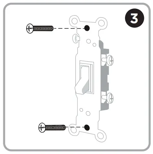
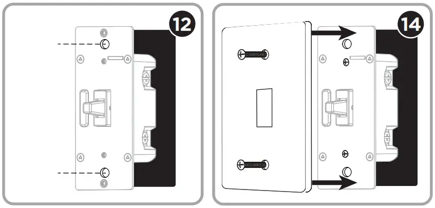
- Insert the switch into the switch box being careful not to pinch or crush wires.
- The switch must be independently mounted (vertical position only).
- Mount the wallplate.
- Reapply power to the circuit at the fuse box or circuit breaker and test the system.

MANUAL CONTROL
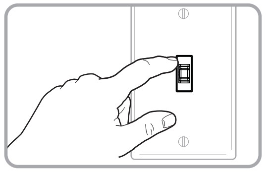
The front panel toggle switch allows the user to turn ON/OFF the connected fixture.
- To turn the connected fixture ON, press up on the toggle switch and release.
- To turn the connected fixture OFF, press down on the toggle switch and release.
CYCLE LED LIGHTAn LED shines behind the toggle to act as a guiding light or status indicator. How to cycle through options: Press up three times and down once quickly.
- LED is always OFF (default).
- LED is always ON (illuminates switch in the dark).
- LED is ON when the load is OFF (guide light in the dark).
- LED is ON when the load is ON (indicates the switch is ON).
CONNECTION
CONNECTING TO A Z-WAVE NETWORK
- Follow the instructions for your Z-Wave certified controller to add a device to the Z-Wave network.
- Once the controller is ready to add your device, press up on the toggle. If prompted by the controller to enter the S2 security code, refer to the QR code/security number on the back of the box or the QR code label on the product.
 https://byjasco.com/HEP-ET/20000-99999/39339 https://byjasco.com/HEP-ET/20000-99999/39339 |
DSK : XXXXX-25651-22671-26939-47599-19612-25872-47752 | 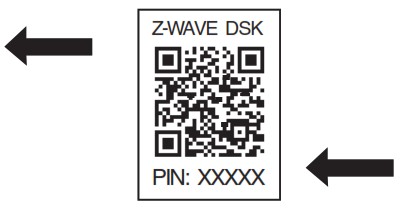 https://byjasco.com/HEP-ET/20000-99999/39339 https://byjasco.com/HEP-ET/20000-99999/39339 |
REMOVING AND RESETTING THE DEVICE
- Follow the instructions for your Z-Wave certified controller to remove a device from the Z-Wave network.
- Once the controller is ready to remove your device, press up on the toggle.
RETURNING SWITCH TO FACTORY DEFAULTSQuickly press up three times, then, immediately press down three times.NOTE: This should only be used in the event your network’s primary controller is missing or otherwise inoperable.NOTE: SmartStart enabled products can be added into a Z-Wave network by scanning the QR code on the product with a controller providing SmartStart inclusion. No further action is required and the SmartStart product will be added automatically within 10 minutes of being switched on in the network vicinity.
![]() This device supports Association Command Class (3 Groups)
This device supports Association Command Class (3 Groups)
- Association Group 1 supports Lifeline, Binary Switch Report, Central Scene notification
- Association Group 2 supports Basic Set and is controlled by pressing the ON or OFF button with the local load
- Association Group 3 supports Basic Set and is controlled by double-pressing the ON or OFF button
- Each Association Group supports 5 total nodes
WARRANTY
Jasco Products Company warrants this product to be free from manufacturing defects for five years from the original date of consumer purchase. This warranty is limited to the repair or replacement of this product only and does not extend to consequential or incidental damage to other products that may be used with this product. This warranty is in lieu of all other warranties, expressed or implied. Some states do not allow limitations on how long an implied warranty lasts or permit the exclusion or limitation of incidental or consequential damage, so the above limitations may not apply to you. This warranty gives you specific rights and you may also have other rights which vary from state to state. Please contact our U.S.-based Consumer Care at 1-800-654-8483 (option 1) between 7 AM – 8 PM, M-F, Central Time, or www.byjasco.com if the unit should prove defective within the warranty period.
SPECIFICATIONS – IMPORTANT!
ZW4009Power: 120VAC, 60HzSignal (frequency): 908.4/916MHzMaximum loads: 960W incandescent, 1/2HP motor or 1800W (15A) resistiveRange: Up to 150ft. line of sight between the wireless controller and the closest Z-Wave receiver moduleOperating temperature range: 32-104° F (0-40° C)Type 1 enclosure, independently mounted (vertical position only), operating control: type 1. c action,pollution degree (2), rated impulse voltage (2500V), software class AFor indoor use onlySpecifications subject to change without notice due to continuing product improvement
Z-WAVE INTEROPERABILITYThis product can be included and operated in any Z-Wave network with other Z-Wave certified devices from other manufacturers and/or other applications. All non-battery-operated nodes within the network will act as repeaters regardless of vendor to increase the reliability of the network.
FCC/IC
This device complies with Part 15 of the FCC and Industry Canada license-exempt RSS standards. Operation is subject to the following two conditions: (1) this device may notcause harmful interference, and (2) this device must accept any interference received, including interference that may cause undesired operation.
FCC NOTE: The manufacturer is not responsible for any radio or TV interference caused by unauthorized modifications to this equipment. Such modifications could void theuser’s authority to operate the equipment
NOTE: This equipment has been tested and found to comply with the limits for a Class B digital device, pursuant to Part 15 of the FCC Rules. These limits are designed to provide reasonable protection against harmful interference in a residential installation. This equipment generates, uses, and can radiate radio frequency energy, and if not installed and used in accordance with the instructions, may cause harmful interference to radio communications. However, there is no guarantee interference will not occur in a particular installation. If this equipment does cause harmful interference to radio or television reception, which can be determined by turning the equipment off and on, the user is encouraged to try to correct the interference by one or more of the following measures:
- Reorient or relocate the receiving antenna.
- Increase the separation between the equipment and receiver.
- Connect the equipment into an outlet on a circuit different from which the receiver is connected.
- Consult the dealer or an experienced radio/TV technician for help.
Important note: To comply with the FCC RF exposure compliance requirements, no change to the antenna or the device is permitted. Any change to the antenna or the device could result in the device exceeding the RF exposure requirements and void the user’s authority to operate the device.Responsible Party – US Contact InformationFCC — U2ZZW4009IC: 6924A-ZW4009Jasco Products CompanyModel: ZW4009/3935410 E. Memorial Rd., Oklahoma City, OK 73114 1-800-654-8483CAN ICES-3(B)/NMB-3(B)
WARNINGRISK OF FIRE RISK OF ELECTRICAL SHOCK RISK OF BURNS CONTROLLING APPLIANCES CAUTION:
- DO NOT EXCEED RATINGS
- DO NOT USE TO CONTROL ANY DEVICE WHERE UNINTENDED OPERATIONCOULD CAUSE UNSAFE CONDITIONS (HEAT LAMP, SUN LAMP, ETC.)
- DO NOT USE TO CONTROL RECEPTACLES
- FOR INDOOR USE ONLY
 report this ad
NOT FOR USE WITH MEDICAL OR LIFE-SUPPORT EQUIPMENTZ-Wave enabled devices should never be used to supply power to or control the ON/OFF status of medical and life-support equipment.
References
[xyz-ips snippet=”download-snippet”]