
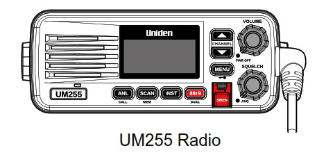
UM25527MHz RadioAM-Marine / AM-CB
For more exciting new products please visit our website:Australia: www.uniden.com.au
OWNER’S MANUAL
Introduction
Features
- Built for Rugged Australian Marine Conditions
- 2 Year Warranty
- Dual Speakers: One speaker is mounted at the front of the unit allowing better sound clarity and the second speaker is built into the microphone handpiece.
- 4 Watts Maximum TX Output Power
- 27MHz Dual Band: The UM255 can operate in the 27MHz AM Marine band for Inshore Boating Radio Services, or the 27MHz AM CB band
- 10 AM Marine Channels | 40 AM CB Channels: Allows you to choose from all the Australian Inshore Boating Radio Services channels, or Australian AM CB channels to transmit or receive messages.
- Splashproof: Meets the world standard JIS4 level. Being defined as no harmful influence by receiving a splash of water from any direction.
- Rugged Speaker Microphone: With Channel Select, One Touch Ch88|9, and Dual Watch keys.
- Variable Squelch Level Knob: Manually adjust the threshold of the receiver to eliminate background noise whenever a transmission is not being received
- Automatic Squelch (ASQ): Set to ASQ to enable the Automatic Squelch.
- Volume Control Knob: Rotary Power on/off and Volume Control
- Backlit Keypad and LCD Display: The keypad and Extra Large Liquid Crystal Display (LCD) is backlit for easy viewing at night or in low light situations, and features a dimmer function
- Built-in PA Output: Connect optional PA speaker for Public Address and Siren Function.
- Siren Alert Function: Alert nearby vessels with connection of an optional PA speaker
- RF Gain Function: Adjust to boost the strength on incoming signals.
- ANL (Automatic Noise Limiter) Function: Reduces unwanted signal noise for better clarity.
- One-Touch Channel 88|9 Recalling: Instantly switch to the emergency Ch 88 (Marine band) or CH9 (CB band) with the touch of one button on the radio or the microphone.
- Open Scan: Scans all the channels in memory and locks on active channels.
- Group Scan (GS) with Priority Channel Watch: Allows the user to select the channel they want to monitor/listen to in a group, along with a priority channel (priority watch).
- Dual Watch Function: Allows you to monitor Ch 88 (Marine band) or CH9 (CB band) for activity intermittently while monitoring another channel at the same time.
- Roger Beep: Confirmation tone indicates the completion of your transmission.
- Call Tone Function: Choose from one of 5 ringing tones to initiate your transmission with the touch of one button.
Manual overview
ConventionsThis manual uses several different type styles to help you distinguish between different parts of the radio:
- BOLD CAPITALS indicates an actual button or knob on the radio or microphone.
- Upper and Lower case bold indicates a connector or label on the radio.
- Italics indicate text on the display, such as menu options, prompts, and confirmation messages.
Getting Started
What’s Included

Parts of the Radio
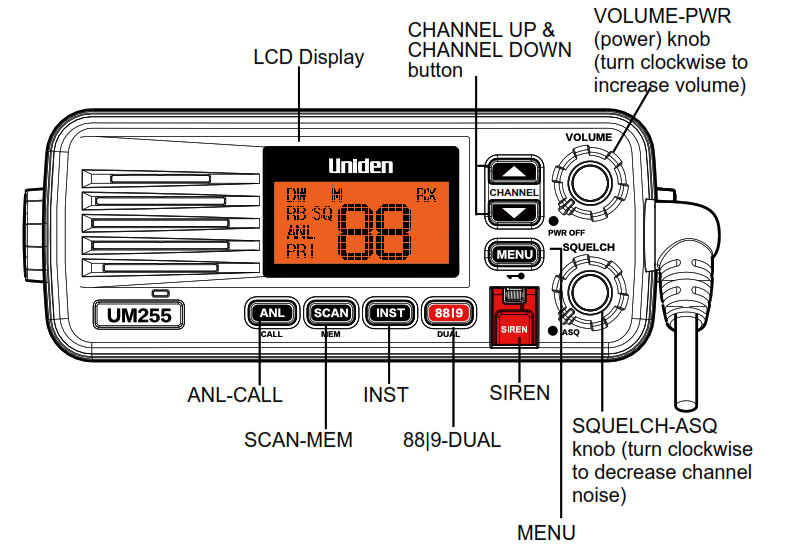
Table 1 – Front panel button functions
| Button | Press to… | Press and hold to… |
| CHANNEL UP | Move up one channel at a time. | Move quickly up the channels. |
| CHANNEL DOWN | Move down one channel at atime. | Move quickly down the channels. |
| MENU | Go to MENU Mode | Key lock |
| INST | Instant (Priority) Channel recall | Save channel as the Instant (Priority) Channel |
| 813I9 I DUAL | Toggle channel between the current channel and CH88 (in Marine band) or CH9 (in CB band). | Select Dual Watch Function |
| SCAN I MEM | Select Scan function | Memory or remove scan channel |
| SIREN | Siren tone one cycle output | Siren tone output continually |
| ANL I CALL | ANL (Automatic Noise Limiter) on/off | Initiate tiate Call tone transmission |

Table 2 – Rear panel connector functions
| Connector | Connects to | For details, see |
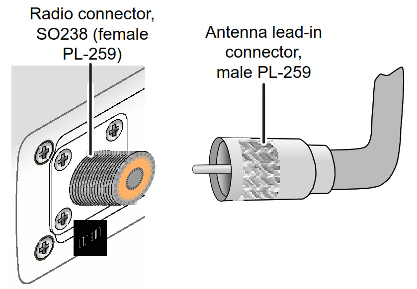
| Antenna connector | External AM antenna with a male PL259 (S0238) connector and 50 0 impedance.Minimum 1.2m, 3dB rated antenna for sailboats, 2.4m, 6 dB rated for powerboats. | Connecting the radio, page 16. |
| Power connector | Nominal 13.8 VDC power supply with negative ground (10.8 VDC to 15.6 VDC) (Red wire +, black wire -). | Connecting the radio, page 16. |
| PA connector | External PA (Public Address) speaker (optional). | Connecting accessories, page 18. |
| Speaker connector | External speaker (optional). | Connecting accessories, page 18. |

Table 3 – Microphone button functions
| Button | Press to… | Press and hold to… |
| PTT (PUSH TO TALK) | Cancel scanning and stay on a channel. | Talk on a channel. |
| 88 I 9 – DUAL WATCH | Toggle channel between the current channel and CH88 (in Marine band mode) or CH9 (in CB band mode). | Select Dual Watch Function |
| CHANNEL UP | Move up one channel at a time | Move quickly up the channels. |
| CHANNEL DOWN | Move down one channel at a time | Move quickly down the channels. |
Using Your Radio
Turning on the Radio
Turn the VOLUME-PWR knob clockwise to turn on the radio.When it powers on, the radio selects the last channel used.
Setting the Band Mode (AM Marine / AM CB)
The UM255 can operate in the Australian 27MHz AM Marine band for Inshore Boating Radio Services, or the Australian 27MHz AM CB band.To switch between band modes:Press and hold INST and 88|9-DUAL buttons of the main unit while turning power on.
Setting the Volume
Turn the VOLUME-PWR knob clockwise to increase the speaker volume; turn it counter-clockwise to decrease the volume.
Setting the Squelch Level (Manual Squelch)
The squelch feature reduces the level of static on the speaker by filtering out the background channel noise. At the lowest squelch level, the speaker plays all radio signals, including any noise on the channel. Setting the squelch level higher filters out channel noise and lets only actual radio transmissions through.
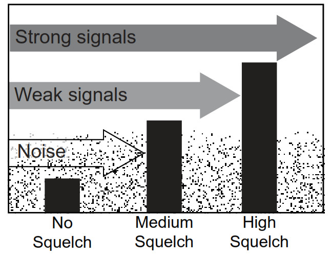
While listening to a channel, adjust the SQUELCH-ASQ knob until the noise is filtered out and you can only hear the transmission. The SQ icon appears on the display whenever squelch is in manual mode (not ASQ mode).If you switch to a channel with a lot of noise or with a weak transmission, you may need to adjust the squelch level again.NOTE 1: Setting the squelch level too high may prevent you from hearing weaker transmissions. If you are having difficulty hearing a transmission, try setting the squelch level lower.NOTE 2: For additional filtering effects, adjust the manual squelch in conjunction with the RF GAIN setting, see page 12.
Enabling the Auto Squelch (ASQ)
Use the Auto Squelch and the radio will be optimized to hear medium to stong (nearby) signals.Turn the SQUELCH-ASQ knob to the ASQ position to enable Auto Squelch mode.The AQ icon appears on the display when ASQ is enabled.
Changing the Channel
Press the CHANNEL UP or CHANNEL DOWN button briefly to scroll through the channels one channel at a time. Press and hold the CHANNEL UP or CHANNEL DOWN button to quickly scroll through the channels.
Making a Transmission
In AM Marine Band mode the UM255 AM radio uses the Inshore Boating Radio Service Band channels.In AM CB Band mode the UM255 AM radio uses the AM-CB Band channels (see Channels and Frequencies, page 22).Select the desired channel. Listen to make sure there is no activity on the channel.Press PTT on the microphone handset and speak normally into the microphone. Hold it approximately 7cm from your mouth. The TX icon appears on the display whenever the radio is transmittingRelease PTT to end the transmission and listen for a reply.
Instant (Priority) Channel
Programmable one-touch Instant channel button.Press INST button to go to the Instant (Priority) Channel.To set the Instant (Priority) channel:First press CHANNEL UP or CHANNEL DOWN to select a desired channel and then press and hold the INST button to store the channel as the Instant (Priority) channel.
Channel 88 | 9Instantly switch to emergency Channel 88 (AM Marine Band mode) or Channel 9 (CB Band mode).Press 88|9-DUAL on the handset or base.
Dual Watch
Dual Watch will monitor the Instant (Priority) Channel and the current channel for activity. Dual Watch is suspended when there is activity and resumes after activity ceases.Press and hold 88|9-DUAL on the handset or base. The DW icon appears and a short tone beep is heard.To cancel Dual Watch press and hold 88|9-DUAL on the handset or base. DW icon disappears.
ANL (Automatic Noise Limiter)
ANL will reduce harsh background noise caused by some transmission interference.Press ANL-CALL to turn ANL ON or OFF.If ANL is ON the ANL icon will remain on the display.
Scanning
The UM255 has a scanning feature that allows you to search for active channels automatically. Furthermore, the UM255 is designed to have two types of scanning;Open Scanning (OS) and Group Scanning (GS), to give you flexibility and allow you to use the radio more effectively.Open Scan Mode (OS)Allows continuous scanning of all selected channels.If an active channel is found, scanning will stop on that channel. If the received signal ceases, the unit will wait 3 seconds for the signal to return, otherwise scanning resumes.The scan direction can be changed at any time by pressing a channel key.After transmission in scan mode, the radio will wait 20 seconds for the signal to return, otherwise scanning resumes.To skip the active channel, press any of the channel keys on the base or handset.
Group Scan Mode (GS)Includes the accessory feature Priority Watch which allows you to monitor the Instant (Priority) Channel while scanning.If the Instant (Priority) Channel becomes active the radio will stay on that channel for as long as the signal is present. If the received signal ceases, GS Scanningcontinues after 3 seconds.If scanning stops on a channel which is not the Instant (Priority) Channel, the UM255 will continue monitoring the Instant (Priority) Channel for activity while listening to the active one.
SCANSelect which Scanning Mode you wish to use, OS or GS (see MENU, page 12)Press SCAN-MEM and Scanning starts and ‘SC’ flashes on the display.Press SCAN-MEM again to exit the scanning mode and return to the initial channel.
MEM: Store/Remove Channels from SCAN MemorySelect which Scanning Mode you wish to use, OS or GS (see Menu, page 12) Select the channel you want to store.Press and hold SCAN-MEM to add channel to SCAN memory. M icon appears and a short tone beep is heard.To remove the channel from SCAN memory, press and hold SCAN-MEM. The M icon disappears.
Menu Order List
| 1. Display Brightness | BRIGHT |
| 2. OS/GS SCAN | SCAN |
| 3. RF Gain | RF GAIN |
| 4. PA Mode | PA MODE |
| 5. Call Tone | CALL TONE |
| 6. Roger Beep | ROGER BEEP |
| 7. Key Tone | KEY TONE |
| 8. SP Mode | SP MODE |
| 9. Contrast | CONTRAST |
Press MENU one time, the Screen Brightness setting flashes on the display.Press CHANNEL UP or CHANNEL DOWN button to select a desired brightness level (total 5 levels).Press and hold MENU to save the setting and exit menu mode.
MENU: OS/GS SCANPress MENU two times, the OS/GS Scan setting flashes on the display.Press CHANNEL UP or CHANNEL DOWN button to select OS or GS.Press and hold MENU to save the setting and exit menu mode.
MENU: RF GAINThe RF Gain function increases the radio’s sensitivity to signals. Set to a high level to better tune to weak signals, or set to a low level if signals are close and strong (distorted). Can be used in combination with the manual squelch.
Press MENU three times, the RF Gain setting flashes on the display.Press CHANNEL UP or CHANNEL DOWN button to select a desired RF Gain level (total 9 levels).The R icon displays whenever the RF Gain is enabled (not set to OFF).Press and hold MENU to save the setting and exit menu mode.
MENU: PA MODEAn optional external PA Speaker is required to use this feature.PA mode redirects the PTT audio to an optional external PA speaker for public broadcast.
Press MENU four times, the PA setting flashes on the display.Press CHANNEL UP or CHANNEL DOWN button to select PA ON or OFF.Press and hold MENU to save the setting and exit menu mode.If PA setting is ON the display shows PA. Pressing 88|9-DUAL also cancels PA mode and changes to the channel to CH88 or CH9.
To use the PA Feature:Press and hold the microphone PTT button. Speak clearly in your normal voice (you don’t have to shout). Use the VOLUME-PWR knob to adjust the volume of the PA speaker. Release the PTT button when you’re finished talking.
MENU: CALL TONECall Tone transmits a wake-up (calling) tone when initiated, (see Front panel button functions, page 5.)To select a Call Tone pattern:Press MENU five times, the Call Tone setting flashes on the display.Press CHANNEL UP or CHANNEL DOWN button to select desired call tone (5 tones). The tone sounds through the speaker when changing selection.Press and hold MENU to save the setting and exit menu mode.
MENU: ROGER BEEPRoger Beep adds a short beep tone pattern to the end of your transmission.Press MENU six times, the Roger Beep setting flashes on the display.Press CHANNEL UP or CHANNEL DOWN button to select Roger Beep ON or OFF.The RB icon displays whenever Roger Beep is on.Press and hold MENU to save the setting and exit menu mode.
MENU: KEY TONEPress MENU seven times, the Key Tone setting flashes on the display.Press the CHANNEL UP or CHANNEL DOWN button to select Key Tone ON or OFF.Press and hold MENU to save the setting and exit menu mode.
MENU: SP MODE (MIC Speaker)Press MENU eight times, the SP Mode setting flashes on the display.Press the CHANNEL UP or CHANNEL DOWN button to select microphone Speaker ON or OFF.Press and hold MENU to save the setting and exit menu mode.
MENU: CONTRASTPress MENU nine times, the Contrast setting flashes on the display.Press the CHANNEL UP or CHANNEL DOWN button to select desired contrast level (total 9 levels).Press and hold MENU to save the setting and exit menu mode.
SIRENFor best results, an optional external PA Speaker should be connected to use this feature.The Siren feature generates a siren output via the Front speaker, Microphone speaker, and optional PA speaker for situations where you wish to alert nearby vessels.
- Single Cycle Siren: Lift the siren cover and press SIREN. The SIREN icon appears and the UM255 emits a siren tone via the Front speaker, Microphone speaker, and optional PA speaker. After one cycle output, the SIREN icon disappears and the UM255 stays in the PA model.
- Continuous Siren: Lift the siren cover and press and hold the SIREN button until the end of the 3-second display count down. The SIREN icon flashes and the UM255 emits a siren tone continuously.
- To cancel the single cycle or continuous siren; Press SIREN or PTT key. The UM255 stays in the PA mode. Pressing 88|9-DUAL also cancels the siren and changes to CH88 or CH9. The siren volume via PA speaker cannot be controlled. The siren volume via Front speaker Microphone speaker can be controlled.
Installing the Hardware
Mounting the radio
The UM255 can sit angled in the mounting bracket so it can easily accommodate the best location. First, determine the best place to mount the radio. For optimum performance, find a location that can:
- Properly support the weight of the radio, approximately 1.1 kilograms. You may need to use some type of anchor with the mounting screws to hold the radio, depending on the surface.
- Keep the battery leads as short as possible.
- Keep the antenna lead-in wire as short as possible.
- Allow free airflow around the heat sink on the rear of the radio.
- Avoid interference with the ship’s compass.
- Install the radio into the mounting bracket, and connect the power cable and accessory cable.
- Position the radio into the desired location. Mark the edges of the bracket on the mounting surface.
- Remove the mounting bracket drill template from the back of the manual, and use the template to mark the drill holes on the mounting surface.
- Drill the holes for the mounting bracket; be sure to follow any special requirements of the mounting surface.
- Remove the bracket from the radio, and use the mounting hardware to secure the bracket to the mounting surface.
- Install the radio back into the mounting bracket.

Installing to an Optional Flush Mount Bracket
A optional FLUSH MOUNT BRACKET is available for mounting the transceiver to a flat surface such as an instrument panel.

Connecting the Radio
To operate correctly, your UM255 requires two electrical connections:• providing it with power from the boat’s electrical system• connecting a 27MHz AM marine antenna to the antenna connector
| Power supply requirements | 27MHz antenna requirements |
| Nominal 13.8 VDC power supply with a negative ground (10.8 VDC to 15.6 VDC).Power leads should be kept as short as possible. A direct connection to the power supply is ideal.Minimum of #14 AWG copper wire for extensions up to 6m, 12 AWG wire for extensions from 6m to 10m, or 10 AWG wire for extensions from 10 to 18m | Male PL-259 connector50 Ω impedanceMinimum 1.2m, 3 dB rated antenna for sailboats or 2.4m, 6dB rated antenna for powerboatsMinimum RG-58 lead-in wire for antenna leads up to 6m to 10m, RG- 8X for antenna leads from 6m to 10m, or RG-8U for antenna leads from 10m to 18m. |

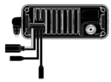
- Connect the BLACK wire of the included power cable to the NEGATIVE (-) side of your power source.
- Connect the RED wire of the included power cable to the POSITIVE (+) side of your power source.
- Connect the power cable to the power connector on the back of the UM255. (The power connector only fits one way.)
- NOTE: To extend the life of the radio, use waterproof tape to seal electrical connections.
- Install your antenna according to the manufacturer’s instructions.
- See Antenna Selection and Installation on page 23 for more details.
- Connect the PL-259 connector from the antenna lead-in wire to the SO238 connector labeled ANTENNA on the back of the UM255.
Connecting Accessories
Connecting to an external speaker
You can use an external speaker to monitor the radio from a different part of your boat or in a noisy environment. If you adjust the VOLUME-PWR knob on the radio, it will also adjust the external speaker volume.The UM255 supports an external speaker with the following specifications:• Minimum impedance of 4 Ohms• Minimum power handling of 10 Watts
1. The External Speaker connection is a standard 3.5mm audio pin connection.NOTE: To extend the life of the radio, use waterproof tape to seal electrical connections.
Connecting to an external PA speakerYou can use an external PA speaker to monitor the radio from a different part of your boat or in a noisy environment. The UM255 supports an external PA speaker with the following specifications:• Minimum impedance of 4 Ohms• Minimum power handling of 10 Watts1. The External PA Speaker connection is a standard 3.5mm audio pin connection.NOTE: To extend the life of the radio, use waterproof tape to seal electrical connections.
Maintenance and Troubleshooting
Due to its rugged design, the UM255 requires very little maintenance. However, it is a precision electronic instrument, so you should follow a few precautions:• If the antenna has been damaged, you should not transmit except in the case of an emergency. A defective antenna may cause damage to your radio.• You should arrange for periodic performance checks with your Uniden dealer.
Common questions
| Problem | Things to Try |
| The radio won’t power on. | Check the power connections.Check the fuse.Check the master battery switch and branch circuit that connect to the radio. |
| The radio won’t transmit. | Make sure you are not in scan mode.Make sure you are not trying to transmit on a receive-only channel (see the channels and frequency tables starting on page 22).Make sure the duration of each transmission is less than 3 minutes. |
| Noise comes out of the speaker all the time | Adjust the squelch level; it is probably too low. |
| I can’t hear anything (no vol- ume) from the speaker. | Adjust the squelch level; it is probably too high. |
| I can transmit, but no one can hear me. | Check your band setting (see Setting the Band (AM Marine mode / AM CB mode) on page ). |
| I can’t read the display. | Adjust the contrast level (see page 14) |
| The display is too bright at night. | Adjust the display brightness level. (see page 12) |
| Where can I find my radio’s serial number? | Look on the rear side of the radio |
Engine Noise SuppressionInterference from the noise generated by the electrical systems of engines is sometimes a problem with radios. The UM255 has been designed to be essentially impervious to ignition noise and alternator noise. However, in some installations it may be necessary to take measures to further reduce the effect of noise interference. The UM255 radio DC battery wires, antenna lead, and accessory cables should be routed away from the engine and engine compartment, and from power, cabling carrying high currents. In severe cases of noise interference, it may be necessary to install a noise suppression kit. Contact the dealer where you purchased the radio for more information.
Specifications
Table 4 – Radio specifications(All specifications are subject to change without notice.)
| General | |
| Controls | Volume-Pwr, Squelch-ASQ |
| Status Indicators | Transmit, Receive, Scan mode, Dual Watch mode, RF Gain on, Roger Beep on, Memory channel, Squelch, Auto Squelch, PA and Channel Display |
| Display | LCD (Dot Matrix) |
| Buttons | MENU-Keylock, Channel UP, Channel DOWN, INST, 8819-DUAL, ANL-CALL, SIREN, and SCAN/ MEM |
| Connectors and Cables | Antenna, Ext.SPKR, Ext.PA, and DC power |
| Size | H 66 mm x W 162 mm x L 100 mm |
| Weight | 1.0 kg |
| Supply Voltage | Nominal 13.8V DC, negative ground (10.8 VDC to 15.6 VDC) |
| Standard Accessories | Mounting bracket and hardware, microphone hanger, DC cable with fuse |
| General | |
| Antenna Impedance | 50 0 nominal |
| Microphone | 2 k0 condenser mic element with coiled cord |
| Speaker | 45mm, 8 0, 2W |
| Operating Temperature Range | 0 °C to + 50 °C |
| Transmitter | |
| Power Output | 4 watt |
| Frequency Range | 26.965 to 27.980 MHz |
| Receiver | |
| Frequency Range | 26.965 to 27.980 MHz |
Channel and Frequencies
Table 5 – Australia 27MHz AM Marine Channels & Frequencies
| Ch No. | Freq. (MHz) | Use |
| 68 | 27.680 | Commercial, Calling ship-ship, shore-shore |
| 72 | 27.720 | Pro. Fishing, Calling ship-ship, shore-shore |
| 82 | 27.820 | Pro. Fishing, Calling ship-ship, shore-shore |
| 86 (.1) | 27.860 | Distress, Safety & Calling (supp. to 27.880) |
| 88 (*1 ) | 27.880 | Distress, Safety & Calling |
| 90 | 27.900 | Non-commercial, Calling & ship-shore |
| 91 | 27.910 | Non-commercial, Calling & ship-shore |
| 94 | 27.940 | Non-commercial, Calling & ship-shore/ship |
| 96 | 27.960 | Non-commercial, Calling & ship-shore |
| 98 | 27.980 | Rescue etc., Calling & ship-ship, shore-shore |
(*1) CH86 and CH88 are emergency CH. Therefore call tone can’t transmit on the CH.Table 6 – Australian 27MHz AM CB Channels & Frequencies
| Ch No. | Freq. (MHz) | Use | Ch No. | Freq. (MHz) | Use |
| 1 | 27. | General | 21 | 27. | General |
| 2 | 27. | General | 22 | 27. | General |
| 3 | 27. | General | 23 | 27. | General |
| 4 | 27. | General | 24 | 27. | General |
| 5 | 27. | General | 25 | 27. | General |
| 6 | 27. | General | 26 | 27. | General |
| 7 | 27. | General | 27 | 27. | General |
| 8 | 27. | Road | 28 | 27. | General |
| 9 | 27. | Emergency | 29 | 27. | General |
| 10 | 27. | General | 30 | 27. | General |
| 11 | 27. | Calling | 31 | 27. | General |
| 12 | 27. | General | 32 | 27. | General |
| 13 | 27. | General | 33 | 27. | General |
| 14 | 27. | General | 34 | 27. | General |
| 15 | 27. | General | 35 | 27. | General |
| 16 | 27. | General | 36 | 27. | General |
| 17 | 27. | General | 37 | 27. | General |
| 18 | 27. | General | 38 | 27. | General |
| 19 | 27. | General | 39 | 27. | General |
| 20 | 27. | General | 40 | 27. | General |
Regulations and Safety Warnings
Antenna Selection and Installation
Your UM255 has been designed to accommodate all of the popular marine 27MHz(HF-AM) antennas.However, the selection and the proper installation of the antenna is the responsibility of the user or installer.The antenna used with this radio should be installed using the following guidelines to ensure a safe distance between the antenna and persons close by.
- Small whip antennas (3 dB) or smaller should be installed at least 1m away from any area where people are likely to be.
- Larger antennas (6 dB or 9 dB) should be installed at least 2m away.
- While the radio is transmitting, do not come closer to the antenna than the recommended safe distance.
- Do not touch the antenna when the radio is powered on and might begin transmitting.
UNIDEN UM255
IMPORTANT Satisfactory evidence of the original purchase is required for warranty servicePlease refer to our Uniden website for any details or warranty durations offered in addition to those contained below.WarrantorThe warrantor is Uniden Australia Pty Limited ABN 58 001 865 498 (“Uniden”).Terms of WarrantyUniden warrants to the original retail purchaser only that the UM255 (“the Product”), will be free from defects in materials and craftsmanship for the duration of the warranty period, subject to the limitations and exclusions set out below.Warranty PeriodThis warranty to the original retail purchaser is only valid in the original country of purchase for the Product first purchased in Australia.
| Product | 2 Years |
| Accessories | 1 Year |
If a warranty claim is made, this warranty will not apply if the Product is found by Uniden to be:(A) Damaged or not maintained in a reasonable manner or as recommended in the relevant Uniden Owner’s Manual;(B) Modified, altered or used as part of any conversion kits, subassemblies or any configurations not sold by Uniden;(C) Improperly installed contrary to instructions contained in the relevant Owner’s Manual(D) Repaired by someone other than an authorized Uniden Repair Agent in relation to a defect or malfunction covered by this warranty; or(E) Used in conjunction with any equipment, parts or a system not manufactured by Uniden.
Parts CoveredThis warranty covers the Product and included accessories.User-generated DataThis warranty does not cover any claimed loss of or damage to user-generated data (including but without limitation phone numbers, addresses and images) that may be stored on your Product.Statement of RemedyIf the Product is found not to conform to this warranty as stated above, the Warrantor, at its discretion, will either repair the defect or replace the Product without any charge for parts or service. This warranty does not include any reimbursement or payment of any consequential damages claimed to arise from a Product’s failure to comply with the warranty.Our goods come with guarantees that cannot be excluded under the Australian Consumer Law. You are entitled to a replacement or refund for a major failure and for compensation for any other reasonably foreseeable loss or damage. You are also entitled to have the goods repaired or replaced if the goods fail to be of acceptable quality and the failure does not amount to a major failure.This warranty is in addition to and sits alongside your rights under the COMPETITION AND CONSUMER ACT 2010 (Australia), none of which can be excluded.
Procedure for Obtaining Warranty ServiceDepending on the country in which the Product was first purchased, if you believe that your Product does not conform with this warranty, you should deliver the Product, together with satisfactory evidence of your original purchase (such as a legible copy of the sales docket) to Uniden at the addresses shown below. You should contact Uniden regarding any compensation that may be payable for your expenses incurred in making a warranty claim. Prior to delivery, we recommend that you make a backup copy of any phone numbers, images or other data stored on your Product, in case it is lost or damaged during warranty service.
UNIDEN AUSTRALIA PTY LTDPhone number: 1300 366 895Email address: [email protected]
Mounting Bracket Template

© 2020 Uniden Australia Pty LimitedPrinted in PRC
References
[xyz-ips snippet=”download-snippet”]