
![]()
ELECTRIC TRAILER JACK 5000-Lb. CAPACITY WITH 7 WAY CONNECTOROWNER’S MANUAL
 Item# UC50010
![]() WARNINGRead carefully and understand all ASSEMBLY AND OPERATION INSTRUCTIONS before operating. Failure to follow the safety rules and other basic safety precautions may result in serious personal injury.
WARNINGRead carefully and understand all ASSEMBLY AND OPERATION INSTRUCTIONS before operating. Failure to follow the safety rules and other basic safety precautions may result in serious personal injury.
SAVE THESE INSTRUCTIONS
INTENDED USE
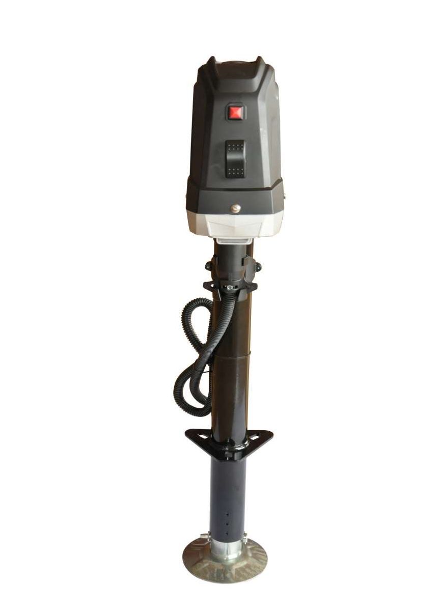
- This 5000LB. Heavy Duty Cargo Electric Trailer Jack is a 12V motor-driven jack that makes couplingand uncoupling from the hitch on travel trailers and boat trailers an easier operation. The ball screwdesign and brake motor increases the lift efficiency and reduces friction. The motor works less,draws less amperage, creates less heat, and produces less noise, which in turn greatly increasesmotor and jack life. The brake motor ensures free to stop at any time, preventing damage caused byhard stops and excessive pressure.
- The 7-way connector plugs into your vehicle connector to let you lift or lower the jack with the push ofa button, no hard wiring is required.
- The plastic connector storage bracket holds your 7-Way connector firmly in place to protect you fromweather, dirt, and damage.
- Your jack is equipped with a new one-piece industrial designed cover for increasing waterproofcoverage. Improved LED lights illuminate the area in front of the jack for superior nighttime visibility.
TECHNICAL SPECIFICATIONS
| Property | Specification |
| Item# | UC500010 |
| Type | 12V DC A-Frame |
| Lift Capacity (lbs.) | 5,000 |
| Support Capacity (lbs.) | 7,500 |
| Clearance: Bracket to Jack Top (in.) | 24 |
| Length of Travel (in.) | 18 |
| Length Retracted (in.) | 9 (Measured from ground to center of the mounting point) |
| Length Extended (in.) | 31-1/2 (Measured from ground to center of the mounting point) |
| Drop Leg Travel (in.) | 4-1/2 |
| Jack Tube Size (in.) | 2-1/4 |
| Crank Type | Includes manual crank handle |
| Ground Support | Footpad |
| Mount Type | A-frame mounting plate |
| Construction | Steel |
| Mount Type | Fits 2 1/4in. mounting holes |
| Mount Height (in.) | 9 |
Tools and Components Required
- A-Frame Coupler with Lower Support Plate (owner supplied, not included)
- Three Grade 5, 1in. Long, 3/8in.-16 UNC Bolts (included)
- Three 3/8in. Flat Washers (included)
- Three Lock Washers (included)
- 9/16in. Wrench (owner supplied, not included)
- Torque Wrench (owner supplied, not included)
- Wire Cutters (owner supplied, not included)
- Wire Strippers (owner supplied, not included)
- Crimpers or Soldering Iron (owner supplied, not included)
GENERAL SAFETY RULES
![]() WARNING
WARNING
- Read and understand all instructions. Failure to follow all instructions listed below may result in serious injury.
- The warnings cautions and instructions discussed in this instruction manual cannot cover all possible conditions or situations that could occur. It must be understood by the operator that common sense and caution are factors that cannot be built into this product but must be supplied by the operator.
IMPORTANT SAFETY CONSIDERATIONS
![]() CAUTION
CAUTION
- Do not allow persons to operate or assemble this electric jack until they have read this manual and have developed a thorough understanding of how the electric jack works.
JACK USE AND CARE
- Do not modify the jack in any way. Unauthorized modification may impair the function and/or safety and could affect the life of the equipment. There are specific applications for which the jack was designed.
- Always check for damaged or worn-out parts before using the jack. Broken parts will affect the jack operation. Replace or repair damaged or worn parts immediately.
- Store idle jack. When the jack is not in use, store it in a secure place out of the reach of children. Inspect it for good working condition prior to storage and before re-use.
- Do not force the trailer jack. Do not attempt to lift more than the maximum lifting capacity of 5000lbs.
- The trailer jack is designed for vertical loading. Excessive side forces may cause jack failure and must be avoided.
- Never attempt to adjust the drop leg when there is any load on the jack. When using the drop foot or drop leg, make certain the supplied pin is fully inserted through both sides of the inner tube and the drop tube before using the jack.
INSTALLATION INSTRUCTIONS
Before installation, compare the lift capacity of the electrical jack with your trailer to ensure the safe operation of the jack.
- Park the trailer on a level surface and block the wheels.
- This trailer jack has been designed to attach to the top surface of the A-frame coupler.
- Disconnect the trailer battery ground trailer.
- Detach the drop leg (#8) of the jack by removing the lock pin and sliding it out.
- Position the drop leg (#8) in line with the mounting hole with the foot of the drop leg on the ground.
- Support the trailer tongue by the frame with jack stands.
- If replacing an old jack, remove the old jack from the coupler, saving the washers and bolts.
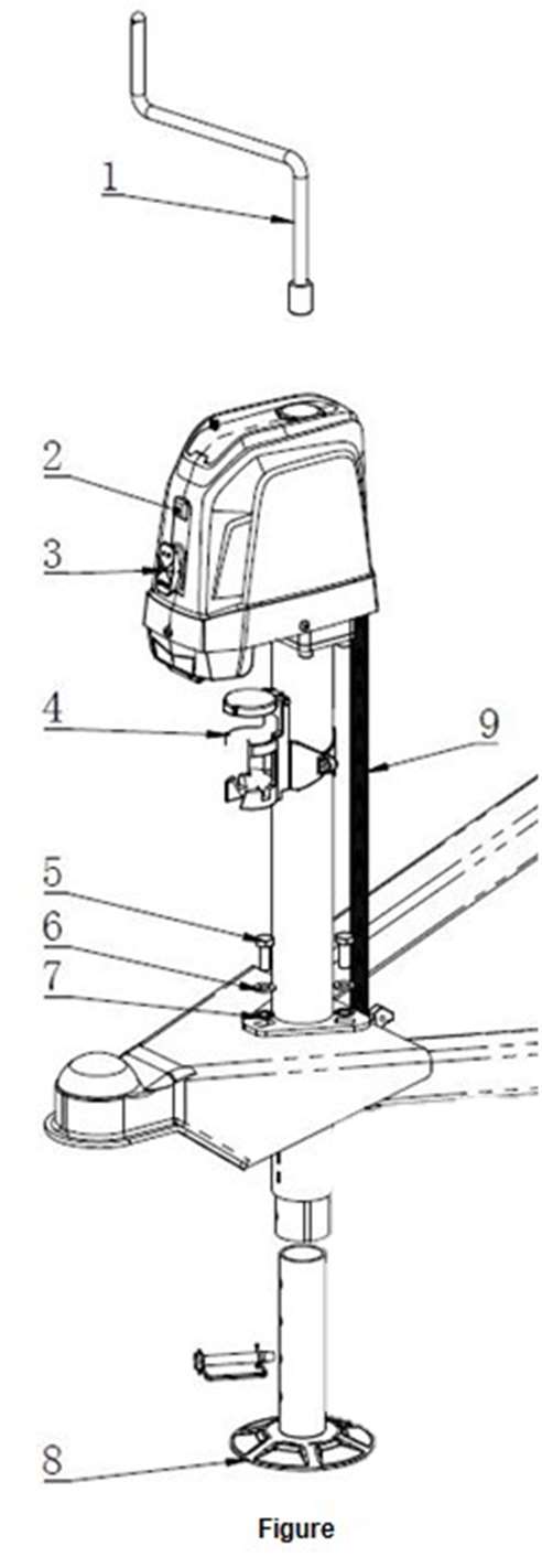
- Insert the electric jack into the jack hole and aligning the bolt holes so the motor housing is facing forward as shown in Figure 1.
 Tip: For extra clearance and convenience, the connector storage bracket can be removed from the rear of the jack and installed on the trailer, frame, or other convenient location.
 - Secure the jack with three Grade 5, 3/8in.-16UNC bolts and washers. Remove paint from around one bolt hole on the jack, and from around the matching bolt hole on the trailer tongue. If the paint layer is thick, add a flat washer between the jack and the trailer to provide good contact. Exposed metal can be painted after assembly to prohibit corrosion. Bolts should be tightened to 15-20 ft.-lbs.Tip: The salvaged bolts from the old jack are acceptable for reuse if they are Grade 5 and in good condition. they are Grade 5 and in good condition.
- If a lower support plate is not already present, install one in the bottom of the trailer frame. Do notoperate the jack without a lower support plate.
- Route the wire lead from the plastic cover along with the trailer to the battery. Attach the wire lead to thetrailer using cable ties or equivalent.
- Connect the unit wire lead from the jack directly to the positive terminal of the battery. This unit has a built-in circuit breaker that automatically trips and resets. Reconnect the battery ground This unit includes a 7- way connector; just simply connect the pin connector to the towing vehicle, no hard wiring is required.
 Tip: For extra clearance and convenience, the connector storage bracket can be removed from the rear of the jack and installed on the trailer, frame, or other convenient location.
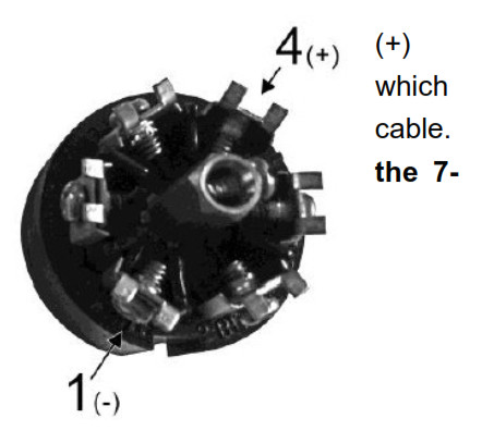
Tip: The trailer connector on the vehicle must match the trailer connector on the jack to power it.Test that the correct terminal is receiving power with a test light. Number 4 on the connector will receive power. Connector number 1 is the neutral ground. Consult a qualified technician on replacing the connector if there is a mismatch between the vehicle and jack connectors.
MAIN PARTS
| Reference | Subassembly |
| 1 | Hand Crank Handle |
| 2 | Light Switch |
| 3 | Extend / Retract Motor Switch |
| 4 | Connector Storage Bracket |
| 5 | (3) Graded 5. 1 in. long, 3/8in.-16 UNC Bolts |
| 6 | (3) 3/8in. Flat Washers |
| 7 | (3) Lock Washers |
| 8 | Drop Led |
| 9 | 7-way connector |
OPERATION
- Park the trailer on a level surface and block the wheels.Tip: For nighttime hookups, turn the light switch (#2) ON to illuminate your work area.
- Before operating the jack, extend the footpad (#8) to the appropriate length and secure it in place withthe 3/8” safety lock pin provided. WARNINGDo not stack blocks under the jack’s foot to increase the height. Stacked blocks may become unstable and fall.
- Extend the jack by pushing the operating switch (#3) UP.Note: Under heavy use, the internal circuit breaker may open, causing the motor to switch off. In thiscase, release the operating switch, and wait 15 seconds for the breaker to reset before resuming operation.
- Retract the jack by pushing the operating switch (#3) DOWN.Note: The jack will stop automatically at the end of the extension or retraction stroke. If you attemptto extend or retract the jack and it does not respond, it may be at the end of the stroke. If the jackfails to respond, try operating it in the opposite direction. If it will not operate in either direction referto the troubleshooting guide.
- After hitching the trailer to a tow vehicle, slide the footpad (#8) fully into the jack tube, secure it with the safety lock pin and retract the jack tube. You may have to raise the jack tube slightly to release pressure on the safety lock pin.
- Before driving, remove the foot or position it in the highest position and completely retract the jack.
MAINTENANCE
To keep your jack in good, functional condition, fully extend the jack and clean the inner jack tube once a year. After cleaning, coat the tube with light grease or silicone spray lubricant.
| Troubleshooting | Refer to the below troubleshooting guide if the device does not function properly or parts are missing. If unable to do so, have a qualified technician service the device |
| Failure | Possible Cause | Corrective Action |
| Motor will not operate Or light is OK,but jack willnot operate. | No or Low Voltage |
Check battery & electrical connections. Must have a minimum of 10 VDC. If the battery is low, plug the trailer cable into the tow vehicle, and start the tow vehicle to provide power to the jack. |
| Poor Ground |
The clean area between the jack mounting plate and coupler, and ensure paint has been removed by the star washers. Direct metal-to-metal contact must exist between mounting components to ensure good electrical contact. Check electrical connections. |
|
| The trailer connector on the jack cannot get trailer power from the connector on the vehicle |
The trailer connector on the vehicle must match the trailer connector on the jack to power it. Test that the correct terminal is receiving power with a test light. Number 4 on the connector will receive power. Connector number 1 is the neutral ground. Consult a qualified technician on replacing the connector if there is a mismatch between the vehicle and jack connectors. |
|
| Open Internal Circuit Breaker | Wait 15 seconds for the breaker to close or replace with a thermal overload protector | |
| Loose Wires on ON/OFF Switch | Secure wire connections | |
| Loose Wires on the Motor | Secure wire connections | |
| Motor Faulty | Replace motor or Replace with a brand new jack | |
| ON/OFF Switch Faulty | Replace switch | |
| Jack can operate but the light doesn’t work | Loose Wires on Light Switch | Check if the light and switch wiring connection is well secured |
| Faulty light and/or switch | Replace light and/or switch | |
| Motor ClutchEngages | If jack leg is at fully retracted or extended position |
| Worn gear | Replace gear |
| Dirty Inner Tube | Clean inner tube and coat with light coat of silicone spray |
| Bent Inner Tube | Replace inner tube |
| Clutch Faulty | Replace motor |
| Jack at angle | Secure mounting bolts and ensure a support plate is used |
| Excessive tongue weights | Determine if jack is adequate for tongue weight |
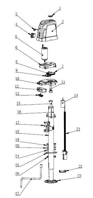
ENLARGED ELECTRIC JACK PART VIEW
PART LIST
| PartNumber | Part Description | Qtv. |
| I | Crank Rubber Lid |
1 |
| 2 | Plastic Housing |
1 |
| 3 | LED Light Switch |
1 |
| 4 | Extend / Retract Motor Switch |
1 |
| 5-10 | Brake Motor box assembly |
1 |
| 11 | Drive Shaft |
1 |
| 12 | Light Cover |
1 |
| 13 | LED Light |
1 |
| 14 | 20A Automatic Thermal Protection |
1 |
| 15 | Ball Screw |
1 |
| 16 | Inner Tube |
1 |
| 17 | Plastic Connector Storage Bracket |
1 |
| 18 | Outer Tube |
1 |
| 19 | Graded 5, I in. long, 3/bin.-I6 UNC Bolts |
1 |
| 20 | Flat Washers |
1 |
| 21 | 7-Way Connector |
1 |
| 22 | Lock Pin |
1 |
| 23 | Removable Footpad |
1 |
| 24 | Lock Washers |
1 |
| 25 | Mounting Plate |
1 |
| 26 | 3/8″-16UNC-2B Lock Nut |
1 |
| 27 | Hand Crank Handle |
1 |
WARRANTY
Remember to fill out and send the warranty form included with your electric trailer jack.Your electric jack comes with a 1 YEAR WARRANTY against defects in materials and workmanship. Warranty is void if the electric jack has been damaged, structurally altered by the user or used commercially. Normal wear and tear are not warranted. The manufacturer agrees to repair or replace any defective electric jack at its discretion.Warranty claims will not be honored without your warranty card and the original receipt. Please be sure to fill out the warranty form and attach your original receipt and mail it to the address below. Keep a copy of the warranty form and receipt where you can find it should you ever need warranty work. If any parts are missing on new purchases, please call our customer service team at: 1-888-326-8502.
Uriah Products®, LLCAttn: Warranty Dept.2720 North Commerce Drive, Ave.Springfield, MO 65803
[xyz-ips snippet=”download-snippet”]