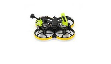
URUAV Flipo F95 User Manual

Package Include
- 1*Flipo F95 PNP
- 1*GEMFAN D63 gray 3-blade Propeller 4 positive 4 negative
- 2*battery strap
- 2*Black battery non-slip mat
- 1* M2*7 Countersunk Screws(6pcs)
- 1* M2*7 Cup head screw(8pcs)
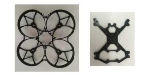
Frame kit
- Wheelbase: 100mm
- Blade size: 2.5inches
- Image transmission hole distance: M2x20x20mm
- Motor pitch: M2x9x9mm
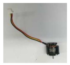
1106-4500KV motor (black)
- Motor KV: 4500rpm/v
- Lipo Cell 2-4S
- Weight 10.8g
- Idle Current IO/10V0.185
- Max Continuous Current 7.0A
- Max Continuous Power 110W
- Max thrus 269G 16.8V/4024R
- Config – ration 12N/14P
- Motor Resistance Rm0.481
- Stator Diameter 13mm
- Stator Length 6mm
- Motor Dimensions 14.2mm*14.5mm
- Overall Shaft Length 4mm
- Shaft Diameter 1.5mm
- Bolt holes spacing:9*9mm
- Bolt thread M2
- Propeller 2.5″
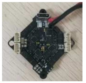
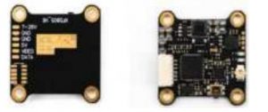
F405 15A AIO FC
FC Parameters:
- CPU STM32F405168MHz
- IMUMPU6000SPI connection
- size 30mm*30mm
- Mounting Hole: 26x26mm
- Firmware GEPR/GEPRCF405
- OSDBuilt-in OSDSTM32 controls the OSD chip via SPI Receiver Stand by FrskyXM/XM+Receiver/Futaba Receiver/Flysky Receiver/TBS Crossfire Receiver
- Programmable LED such as WS2812 :Support
- Built-in current sensor
- Reserved buzzer interface
- Reserved DJI port
- Weight 6.4g
ESC ParametersBLHELI_S all functions:Support PWM One shot 125 Oneshot 42Multishot Dshot 150Dshot300 Dshot600: Support
- Input voltage 2S-4SLipo
- Constant current 12A
- Peak current 18A
- CPUEFM8BB21F16G Motor
- connector 1.25mm pin header connector
- Firmware G-H-30-16.7
Run Cam Nano 2 FPV Camera
- Item: Run Cam Nano 2FPV Camera
- Beeld sensor: 1/3 “CMOS
- Horizontale Resolute: 1200 TVL
- Lens: 2.1mm (M8) FOV 155 °
- Signal System: NTSC / PAL
- S/N Ratio: >50dB
- Electronics Sluitertijd: Auto
- Auto Gain Control (AGC): Auto
- Min. Verlichting: 0.01Lux1.2F
- D-WDR: Auto
- Dag/Nacht: Kleur
- Power: DC 3-5.5V
- Stroom: 110mA @ 5V 120mA3.3V
- Behuizing Material: ABS
- Netto Gewicht: 3.4g
- Afmetingen: L14mm * W14mm * H16mm

XF5805/5.8G 40CH VTX
- Support TBS Smart Audio
- Transmitting power:
- 0/25/100/300/400mw Frequency
- Points: 40inch
- Video format: complete NTSC / PAL
- Format Input voltage: 7V26V
- Power consumption: +12V600MW, 260ma @
- Size: 25×20×4mm
- Weight: 3.2g (except for antenna)
Equipped with copper tube mini antenna (ipex interface) Ps: The antenna must be installed before power on to avoid the possibility of burning the tuner.
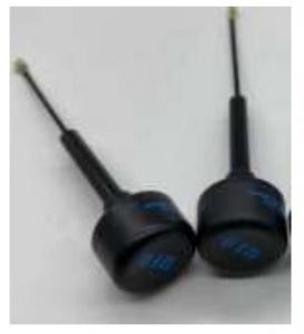
5.8G IPEX left-handed antenna
- Frequency range MHz56005950MHz
- Polarization Right-handed RHCP
- Input Impedance 50
- VSWR5800MHZ1.5
- Maximum input power 50W
- Input connector type: UFL
- Size 15*78MM±2
- Antenna weight 2.5g
- Radome material ABS
- Radome color black
- Operating temperature-4060°c
- Rated Wind Velocity 60m/s
GEMFAN 63mm 2.5 inch propeller
- Specification: D63
- Diameter 2.5inch
- Paddle diameter 63.5MM
- Materialim ported Bayer PC
- Mounting holes 1.5MM/4 holes
- Center thickness :4.9MM
- Quantity: 2pairs
- Color black
- Weight 1.4g/PCS
Recommended power supply
- Recommended voltage: 2S-4S
- Recommended capacity: 350-900 Mah
Adjusting Parameter:
(1) Configuration of UART port parameters
Enter the Ports item, select the UART port (UART3 in this case), and then select the TBS Smart Audio item (Figure 1) in the Peripheral column to complete the configuration of the flight control image serial port. If the connection between the image transmission and the selected flight control UART port remains unchanged, this step only needs to be operated once.

(2) Frequency grouping and channel number configuration ![]() Enter OSD parameter menu
Enter OSD parameter menu
When VTX1 image transmission, corresponding image transmission receiver display screen and flight control are powered on, the information shown in Figure 2 will appear on the receiving screen.

Figure 2 Electrical display information At this time, according to the screen prompt operation THR MID
(throttle center), YAW LEFT (YAW rocker to the left), PITCH UP (PITCH rocker to the top) into the OSD parameter adjustment menu (Figure 3).
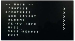
Figure 3 OSD parameter menu
![]() Start grouping and channel configuration
Start grouping and channel configuration
Under the OSD MAIN menu, the PITCH rocker can move the cursor arrow up and down to select the menu item, select the FEATURES item, then select the ROLL rocker to the right, and enter the lower configuration menu (Fig. 4).
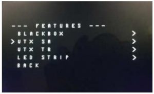
Figure 5 FEATURES Menu
In the menu of Figure 4, select the desired frequency grouping BAND and channel CHAN by swinging the ROLL rocker left and right.
Note: Because VTX1 supports 48 channels, users can select any of the 48 channels by pressing keys. But at present, Beta flight’s OSD parametric function only supports 40 channels, so users can only configure 40 channels on the OSD screen. If the user chooses one of the eight channels that OSD parameters do not support and enters OSD parameters, the system will automatically change the user’s original channel to A1 channel on our frequency table (5865 MHz), that is, the user can configure only 40 channels with OSD parameters. After configuring the grouping and channel, you need to enter the SET item and select YES to take effect (Figure 6).

Figure 6 Grouping and channel configuration validation
![]() Output power configuration
Output power configuration
As in the previous section, the POWER item can be entered by remote control selection, and the required transmission power can be selected (Fig. 7). VTX1 currently supports only 25 mW power options, while the POWER menu with OSD parameters has four options: 25 mW, 200 mW, 500 mW and 800 mW. Therefore, users need to pay attention to the choice of 200 mW, 500 mW, 800 mW options will be VTX1 set to 25 mW transmission power. Note: Unlike configuring BAND and CHAN, POWER settings do not need to enter the SET entry confirmation, and take effect immediately.
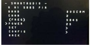 Figure 7 Transmission Power Selection
![]() Channel number indication
Channel number indication
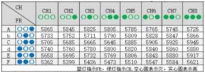
The LED lamp displays the set grouping and channel, and the corresponding working frequency is shown in the table below.
Channel select :
Select channels by simple short presses. Blue LED light on stands for CH1,short presses to change 8 channels sequentially.
Band select:
Press button for 2S,Green LED will flash,then short presses to select 5 bands.
Power select:
Press button for 4S,Red LED will flash,then select power by simple short presses to select 25mW/200mW/600mW/800mW.Blue light indicates FR, green light indicates CH, hollow circle indicates off, solid circle indicates ON
Precautions for use:
Before power on, make sure that the output terminal has an antenna installed to avoid damaging the internal components; Note that the input voltage is within the specified range and positive and negative, so as to avoid damaging the internal components; If you want to change the antenna, please choose the antenna with good standing wave and gain to get a long transmission distance; Pay attention to electrostatic protection during transportation, installation and use;
[xyz-ips snippet=”download-snippet”]