UTG ACCU-SYNC AK Side Mount User Manual![]()
THE BEST NEVER REST WARRANTY – LIFETIME
Leapers®, Inc. warrants that all UTG® & UTG PRO® products conform to published specifications and are free from defects in material and workmanship. We will repair or replace defective products for the duration of the product’s life span. Our dedicated in-house customer service professionals will provide the best-in-class UTG® experience.
NOTES: Our warranty does not extend to products disassembled, damaged from misuse, accidental impact, negligence, natural disasters/accidents, or unauthorized repair or alteration.For any questions regarding the process, please feel free to call us at (734)542-1500 or email us at
,Caution: Make sure firearm is not loaded. Remove magazine and examine chamber. Use safe handling procedures at all times.
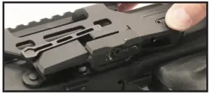
Mount Installation
- Move the quick release lever completely to the left to its unlocked position.
- Slide the mount onto the receiver side rail, pushing the mount until it stops and fully engages the length of the side rail.
- Turn the quick release lever completely back to the right to its locked position and test mount tension. If tension is too loose or too tight and you cannot tum the lever completely to the locked position proceed to “Adjusting Mount Tension” instructions.
- Proper mount retention is achieved when the mount attaches securely to the receiver side rail without any movement forward, rearward, up, or down with the lever in its locked position.The amount of force required to lock and unlock the quick release lever should not be excessive. The action of doing so is however a deliberate one and some resistance will be felt.
Adjusting Mount Tension
The ACCU-SYNC® AK Side Mount is tension adjustable and requires no tools for making adjustments in the field. A hex key is however provided to make adjustments easier up front.
- Start with the mount in its unlocked position while installed on the receiver side rail (at times it may be easier with the mount uninstalled from receiver side rail).

- Press and hold down the spring-loaded side plate and locking tab located at the bottom center of the mount to allow clearance for the adjustment gear to rotate.
- Insert the long-end of the hex key into the adjustment gear.• Rotating the adjustment gear counterclockwise increases tension. Tension adjustment should not exceed 20in-lbs.• Rotating the adjustment gear clockwise decreases tension.
- Once proper tension is achieved, release the spring-loaded side plate and locking tab ensuring the gear returns to its keyed position.
M-LOK® Accessory Installation
 report this ad
- Ensure the gap between the M-LOK® T-nut and corresponding raised boss is slightly larger than the thickness of the boss itself.• If the gap is too wide, the T-nut will not engage properly and will free-spin.• If the gap is too narrow, the T-nut will not be able to rotate.
- When correctly positioned, the T-nut will tighten and seat perpendicular to the M-LOK® mounting slot.• Recommended torque value is 30in-lbs.
Read More About This Manual & Download PDF:
[xyz-ips snippet=”download-snippet”]