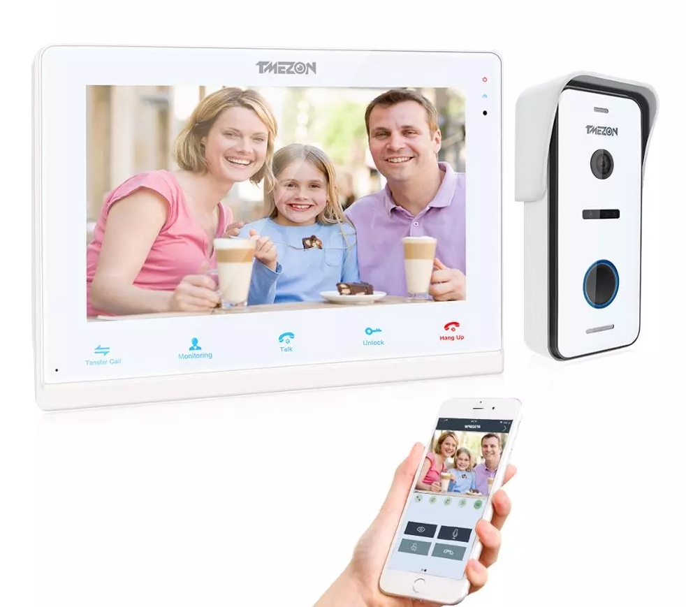
WiFi Video Intercom System Indoor Monitor User Manual

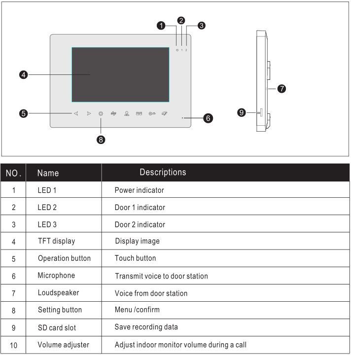
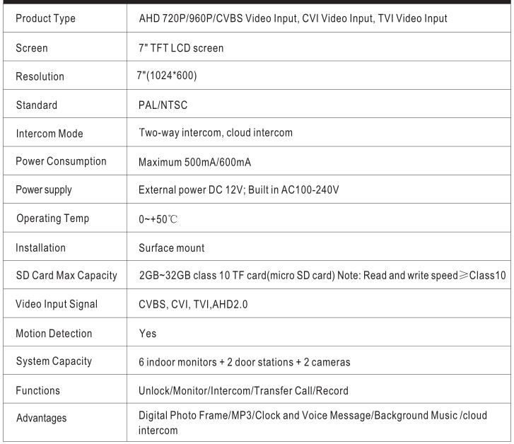
INDOOR MONITOR SPECIFICATION
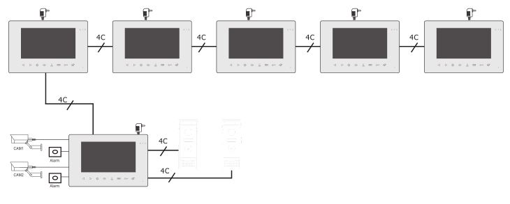
SCHEMATIC DIAGRAM
Indoor monitor schematic diagram as below, actual operation follows installation diagram.
INSTALLATION SAFE NOTES
- Electrical locks/alarms/cameras are not included in the package, you can buy electrical locks that fit the actual requirements
- Factory default supports the lock of the normally open (NO) unlock mode, dry contact is opened in the normal state, lock remains normally dosed. If press unlock button, the dry contact becomes dosed, Release the lock.
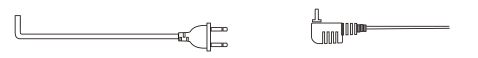
- Built-in or external power supply is optional. Suitable for a wide voltage range (AC100V-240V). Unplug the AC power plug before installing the device (shown as below).

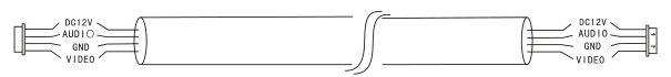
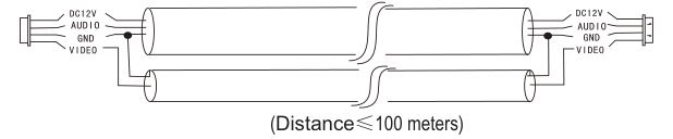
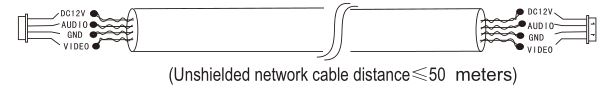
- For the use and selection of wires, please refer to the following. (cable quality influence video and voice transfer distance)
- 4C ordinary unshielded wire and shielded wiringDistance≤28m(4*0.2mm²); Distance≤50m(4*0.3mm²); Distance≤80m(4*0.5mm²)
- 3C ordinary unshielded + video cable(RG-59) connection method
- Category 5 network cable connection (not recommended)
- 4C ordinary unshielded wire and shielded wiringDistance≤28m(4*0.2mm²); Distance≤50m(4*0.3mm²); Distance≤80m(4*0.5mm²)

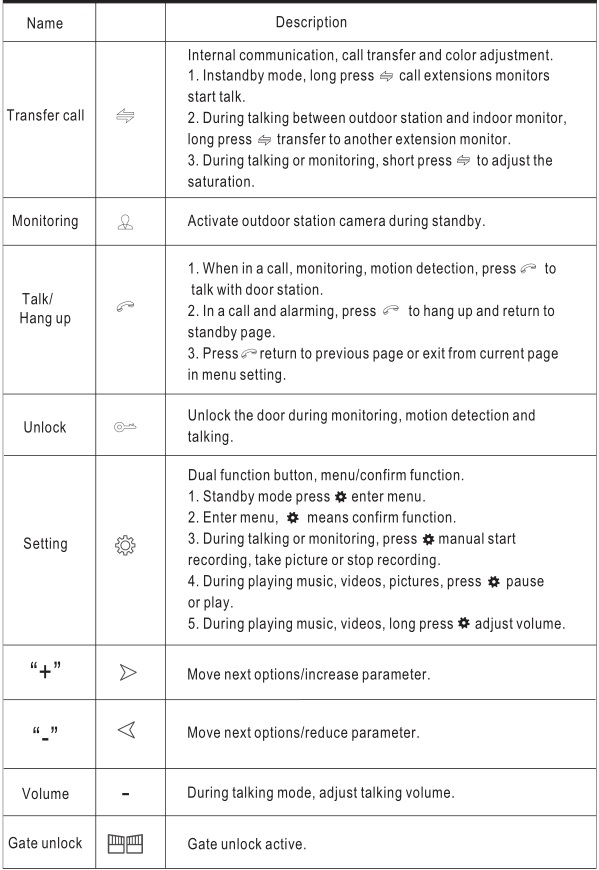
OPERATION INTRODUCTION
VISITOR CALL
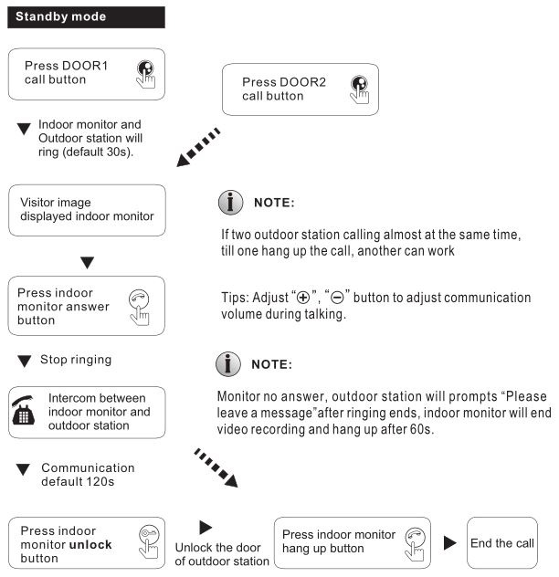
- Unlock time default 2s. Answer and press unlock, auto back to standby mode after 20s.
- Insert SD card and set it as video record mode, recording will active from calling till hang up. Recording will be stop after press .
- Insert SD card and set it as snap, during talking press active snap.
- During talking, can’t be switch extension camera image.
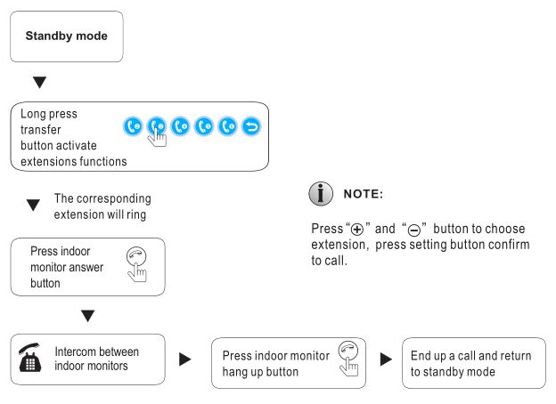
CALL TRANSFER TO OTHER EXTENSIONS
Install two indoor monitors and one door station can use above function.
![]()
INTERCOM BETWEEN MONITORS
At least 2 indoor monitors are required.
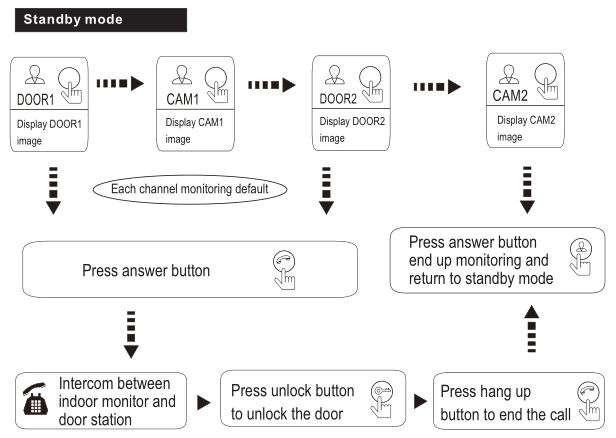
MONITORING
Default factory mode, DOOR2, CAM1, CAM2 status are ON.
NOTE:
- When with 1 door station only, can press monitor button again to end monitoring, and can press hang up button to end (DOOR2, CAM1, CAM2 must be OFF)
- If use 2 indoor monitors, can turn on monitor mode on other extensions, the same image will show difference extensions.
- When visitor press door station call button, system will turn off monitor mode and switch to show door station calling image.
- When record mode is video record, press setting button to start video recording, press setting button again to stop recording.
- Insert SD card and set it as snap mode, press setting button to snap a picture, and snap more pictures.
MOTION DETECTION
Door station camera detect moving, auto start motion detection and display image on monitor.

- Press Setting Button >Mode > Motion Detection to enter the mode to select motion detection object like Door1, Door2, CAM1, CAM2.
- Back to standby mode after 10s activate motion detection function.

STANDBY MODE
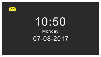
Standby page with two modes: clock mode and digital photo frame mode.
- Clock ModeDisplay year, month, day, week, hour, minute, second. The clock will be displayed in standby mode for 60 seconds, then enter a black screen saver. Note: New unread message icon will displayed in the upper left corner.
- Digital photo frame modeIn Digital Photo Frame mode, the Monitor cycles through the photos in the \USER\Photo directory on the microSD card.

NOTE:
- By default, the clock is displayed on a monitor with If the digital photo frame function is ON, the image saved in microSD card will be automatically played in standby mode.
- It needs to create “photo” file in the “USER” folder of SD Pictures must be saved in “photo” folder to be found and displayed.
In standby mode, press setting button to enter main menu page. The main menu page is shown as below picture. The main menu includes system, time, digital photo frame, mode, multimedia, and record center. On the menu, press the “plus” or “minus” button to the specific option, and press the return button to return to the standby mode.
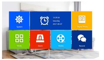
Automatically back to standby mode after 60s without operation.
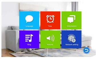
- Parameter Settings“System” menu includes: language, time, system information, ringtone, volume, network settings.
- System – LanguageEnter language menu and press , the arrows on both sides of the “Language” option will change color to indicate that you can adjust. Press (+) or (-) button to switch language. After adjustment, press setting button again.
- System – TimeAdjust monitor time from “Time” page.
- Select Clock Switch on/off decided display standby mode.
- Three type mode of date format : YY-MM-DD, MM-DD-YY, DD-MM-YY. Select “Date Format” and press . The arrows change color to indicate that you can adjust the value. Press (+) or (-) to switch the format. Press again to set the language successfully.
- “Date”, “Time”: The time is displayed in 24-hour format.
- System – InformationSelect “System Information” and press to enter the “System Information” menu.System information includes: software version, MCU version, microSD card free space, Restart/ Reboot the Monitor and Format the microSD card, Mac address, ID Number.Note: Supports microSD cards with write speeds over 10MB/s and memory below 32G[Reboot]: To restart the Monitor, select “Confirm” and press . Select “Yes” to the pop-up prompt to “Reboot device?”. Otherwise, select “No” to exit the window without rebooting.[Format]: Select “Format” button and press “Yes” to start formatting SD card.[Get ID]: Select this to update manufacturer device ID information from a microSD card(if directed by our Technical Support team)
- System-RingtoneIn “System Menu”, press (+) or (-) to “ringtone”, and then press to enter the “ringtone” page. Set the ringtone of the indoor monitor.[Mode]: Ringtone mode includes two types: Default ringtone and defined ringtone.Default ringtone: refers to the ringtone that comes from the system.Defined ringtone: The user adds a ringtone stored on the SD card. When the mode is set to Defined, the door station calls indoor monitor come with customized ringtone.[Door1/2 Ring]:Set default ringtone and defined ringtone of door station. When the mode is selected as default, display default ringtone, and when the mode is selected as defined ringtone, display defined ringtone.NOTE:
- Create a “\USER\Ring” directory on the microSD card. Only music stored in this ring folder can be used as Custom ringtones.
- The ringtone name must be ring_1~ring_10.
- The ringtone files must be in MP3 format.
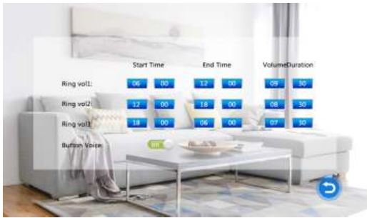
- System-VolumePress (+) and (-) enter “Volume” page. Can set 3 different ringtone volume and ringing time.Note: Volume setting is to set calling volume.[Ring Vol1]: Ring volume can set 0-10, ring time can set 10s-45s.[Ring Vol2]: Ring volume can set 0-10, ring time can set 10s-45s.[Ring Vol3]: Ring volume can set 0-10, ring time can set 10s-45s.[Button Voice]: This turns on/off the confirmation sound when a button is pressed.[Door station ringtone]: Control door station ringtone on/off.
- System-Network SettingsSelect “WiFi Set”———- “network setting”. Monitor connect to Wifi, once outdoor station call, monitor and smart phone APP will ring
- APP Download and Register
- Download “Tuya smart” app, IOS system from the Apple Store; Android system from Google Play.
- Switch on “Tuya smart” app, register new account should select country and region.
- Login to the app after registration is complete.Note: Wireless network setting must be used with the mobile phone APP (Tuya smart).
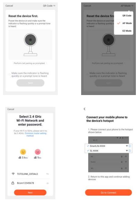
- AP Mode Connection Steps:
- Power on indoor monitor, it will start a hotspot named SmartLife-xxxxxx.
- Turn on the phone, click “Settings”-> “WiFi” check hot spot SmartLife-xxxxxx If yes, go to step 4. If not, go to step 3.
- Select the AP mode from indoor monitor and press two times setting button to The indoor monitor will auto reboot and start the WiFi hotspot named SmartLife-xxxxxx.
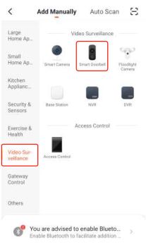
- Switch “Tuya Smart” App, press “add device” or “+”, enter page as below.
- Select “Smart Doorbell” under “Video Surveillance”, enter page as below.
- Select “Net Paring Mode”——-”AP Mode”—————- ”Enter Wifi name and Password”
- Turn on smart phone “Setting”–>connect wifi “SmartLife-xxxxxx”–>back to “Tuya Smart”APP, waiting process finished 100% successful connected.
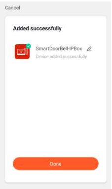
- Wait for progress to complete 100%, mean connection successfully.
- After connect WiFi successfully, the WiFi icon and server icon appear in the upper left corner of the indoor monitor in standby mode.NOTE:iOS mobile phones may encounter the situation where the WiFi automatically switches to other home WiFi when connected, resulting in unsuccessful connection. Please forget all connected home WiFi on the phone before connecting.
- APP Download and Register
- System – LanguageEnter language menu and press
- Digital Photo FrameIn Digital Photo Frame mode, the Monitor cycles through the photos in the \USER\Photo directory on the MicroSD card.Note : If Digital Photo Frame is turned ON, then motion detection function not allow to use.[Digital Switch]: User can select it on/off, default off.[Interval Time]: Digital Photo Frame playing time control default 6 second, for user select 2-10 second option.NOTE:
- Create “Photo” folder under “USER” in MircoSD
- The pictures must be below specification:MAX_RESOLUTION_WIDTH ≤ 1920;MAX_RESOLUTION_HEIGHT ≤ 1080;JPEG_FILE_MAXSIZE ≤ 3 MB;
- Mode SettingSelect “Mode” and press to enter the “Mode” menu. Can set extension number, DOOR2 status, unlock time, recording mode, motion detection, message etc. [Set machine ID]: Options with “01, 02, 03, 04, 05, 06”. “01” indicates master monitor, and “02 ~ 06” indicate extensions.[Door2 status]: DOOR 2 viewing ON or OFF.[Door1 Unlock Time]: Set DOOR 1 unlock time. After unlocking, unlock time ends and DOOR 1 lock closed. The unlock time can be set from 2 to 10 seconds, default time is 2 seconds.[Door2 Unlock Time]: Set DOOR 2 unlock time. After unlocking, unlock time ends and DOOR 2 lock closed. The unlock time can be set from 2 to 10 seconds, default time is 2 seconds.[Record mode]: Options include: Video and snapshot. Recording means when visitor call, indoor monitor with the SD card will automatically start recording until the call ends or the user presses to end recording. Snapshot means when visitor call, indoor monitor with the SD card will automatically start snap a picture or press setting button to snap a picture manually.Note: Recording mode is only effective for DOOR 1, DOOR 2.[Motion Detection]: Options include “Door 1, Door 2, camera 1, camera 2, Close”. Can choose an outdoor device to detect.[Message]: Turn ON or OFF message reminder, default is ON. If a visitor calls, he/she will be prompted to leave a message if the resident is not at home or fails to answer the call.
- AlarmSelect “Alarm” and press to enter “Alarm” menu. Including: Alarm Record, Sensor Type, CAM 1, CAM 2, Ring Time[Alarm record]: Options include: video and snapshot. Recording means when an alarm is triggered, indoor monitor with SD card automatically starts recording until alarm ends or the user manually stops by pressing hang up button. Snapshot means when an alarm is triggered, indoor monitor with SD card will automatically take a picture of sensor camera device. The user can also manually press setting button for continuous snapshots.
Note: Alarm record is only for CAM1 and CAM2, alarm duration is 2 minutes.
[CAM1 Sensor type]: CAM1 channel corresponds to i / o state (see below description), which means when an alarm is triggered, it will activate the corresponding channel to start alarm video recording or capture a picture.
[CAM2 Sensor type]: CAM2 channel corresponds to i / o state (see below description), which means when an alarm is triggered, it will activate the corresponding channel to start alarm video recording or capture a picture.
[CAM1]: CAM 1 viewing ON or OFF.
[CAM2]: CAM2 viewing ON or OFF.
[CAM1 ring time]: CAM1 alarm ring time can be set from 0 to 20 seconds. [CAM2 ring time]: CAM2 alarm ring time can be set from 0 to 20 seconds.
I/O Status Types:
NO: It means it is in normal state, the sensor at a constant low pressure. If output voltage goes from low to high, the alarm is triggered.
NC: It means that in its normal state, the sensor is kept at a constant high voltage. If the output voltage goes from low to high, an alarm is triggered.
OFF: If the external sensor alarm is not used, set i / o to “OFF”.
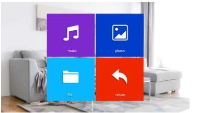
- Multi MediaSelect “Multimedia” and press to enter “Multimedia” menu. It includes: Music, Photo, File Management.
- MusicSelect “Music” and press to enter music playback page. After entering music page, the first music in the list is automatically played.
Note: Using a computer, create a “USER” folder and then a “Music” subfolder on the microSD card. Only MP3 music files located in the “Music” subfolder will be displayed. Important: The “\USER\ Music” directory is case sensitive.
- Enter the music list, select it and press setting button start play music.
- Press and hold to bring up volume, and press > to increase volume or press < to decrease volume.
- Playing music mode: Play In Sequence, Single Play, Single Cycle, List Cycle, Random[Single song playback]: Stop playing automatically after playing the current song.
[Random play]: play all songs randomly without stopping playback.
[Sequential play]: play all songs from top to bottom, stop playing after the last song is played.
[Single loop]: Play the same song repeatedly without stopping playback.
[List loop]: Repeat all songs in sequence. After the last song is played, it will be played in the loop from the first one.
Note: If a visitor calls or triggers alarm during playback, the playback will stop and switch to door station or camera image.
- Photos (for the models with MicroSD card)Select “Photo” in the Media menu. Press setting icon to view the list of photos.NOTE:
- Photos must be stored in the “\USER\Photo” folder on the MicroSD card in JPG The directory is case sensitive.
- Maximum display size of photos:MAX_RESOLUTION_WIDTH ≤ 1920;MAX_RESOLUTION_HEIGHT ≤ 1080;JPEG_FILE_MAXSIZE ≤ 3 MB;
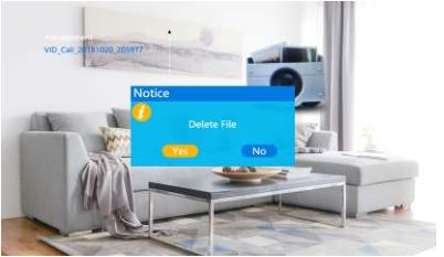
- File ManagementSelect “File Management” option, press to enter “File Management”, select microSD folder, and press to enter microSD card, it includes: DCIM folder, USER folder.
[Delete file]: Press (+) or (-) to delete file option, press and hold
, window pop-up “Delete file?”, select “yes” and confirm to delete file, select “no” and confirm to close pop-ups.[DCIM Folder]: DICM file is programmed automatically created and only save record center file, it includes “photo” folder and “video” folder. “Photo” folder saves automatically captured picture and manually captured picture of indoor monitor, and “video” folder save automatically recorded videos and manually recorded video of indoor monitor.
[USER Folder]: The USER directory contains the “Music, Photo, Ring, Update” folders.
Note: These directory & names are case sensitive.
- “Music” folder stores the MP3 music files.
- “Photo” folder stores JPG pictures for the digital photo frame.
- “Ring” folder stores the custom ringtones.
- “Update” folder for upgrade USER folder stores “Music, Photo, Ring, Update” folders.
[Upgrade]: Put upgrade file (xxx.dd is the program file) in the update folder, select upgrade file xxx.dd and press
to pop up the window “Upgrade?” Select “Yes” and press to confirm upgrade and wait for the upgrade to succeed. “No” Press to close the window.[MCU Upgrade]: Put MCU file (xxx.bin is the MCU file) in the update folder, select MCU file xxx.bin and press
to pop up a window “Upgrade?” Select “Yes” and press to confirm to upgrade and wait for the upgrade to succeed. Select “No” Press to close the window.Note: During system upgrading, do not remove SD card, power off, or disable indoor monitor. After the upgrade is complete, the device will restart.
- MusicSelect “Music” and press
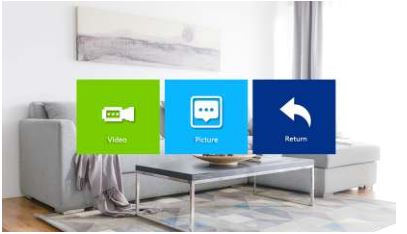
- Select “Record Center” and press to enter “Record Center” menu. Recording center includes: video information, photo information.
Note: If you need to delete the videos and pictures in recording center, please delete them in the DCIM folder in micorSD card.
- RecordingSelect “Recording message” and press to enter recording message list. Select video to be viewed and press to play. During playback, you can press and hold (+) or (-) to fast forward or rewind like a movie, long press to adjust volume, press to end playback and return to recorded message list.Note: The recording message only contains video files recorded by indoor monitor.
- PhotoSelect “Photo message” option and press to enter photo message list. Select picture to play, press to confirm playback, and press to return to current menu.
- RecordingSelect “Recording message” and press
- Color Parameter SettingsIn standby mode, press to monitor. Press during monitoring to bring up color adjustment mode. It includes: brightness, contrast, saturation, refresh, and return. Select the option and press . When color of number changes, press (+) or (-) to increase value or decrease value. Press again to confirm after setting.
Note: Color parameters can be set on the screens of monitoring, calling, calling, alarming, etc.
[Talking Volume]: During talking mode with door station also can adjust talking volume.
[Bright]: The value can be set from 0 to 50, default is 25.
[Contrast]: The value can be set from 0 to 50, default is 25.
[Saturation]: The value can be set from 0 to 50, default is 25
[Refresh]: Refresh door station mechanism. When you change door station of different standards, the image may not be displayed, and you need to refresh and re-detect door station mechanism.
[Return]: Select return, press Set button to close color adjustment mode.


 [Reboot]: To restart the Monitor, select “Confirm” and press . Select “Yes” to the pop-up prompt to “Reboot device?”. Otherwise, select “No” to exit the window without rebooting.[Format]: Select “Format” button and press “Yes” to start formatting SD card.[Get ID]: Select this to update manufacturer device ID information from a microSD card(if directed by our Technical Support team)
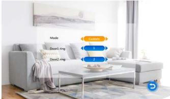 [Mode]: Ringtone mode includes two types: Default ringtone and defined ringtone.Default ringtone: refers to the ringtone that comes from the system.Defined ringtone: The user adds a ringtone stored on the SD card. When the mode is set to Defined, the door station calls indoor monitor come with customized ringtone.[Door1/2 Ring]:Set default ringtone and defined ringtone of door station. When the mode is selected as default, display default ringtone, and when the mode is selected as defined ringtone, display defined ringtone.NOTE:
 [Ring Vol1]: Ring volume can set 0-10, ring time can set 10s-45s.[Ring Vol2]: Ring volume can set 0-10, ring time can set 10s-45s.[Ring Vol3]: Ring volume can set 0-10, ring time can set 10s-45s.[Button Voice]: This turns on/off the confirmation sound when a button is pressed.[Door station ringtone]: Control door station ringtone on/off.

 [Digital Switch]: User can select it on/off, default off.[Interval Time]: Digital Photo Frame playing time control default 6 second, for user select 2-10 second option.NOTE:
 [Set machine ID]: Options with “01, 02, 03, 04, 05, 06”. “01” indicates master monitor, and “02 ~ 06” indicate extensions.[Door2 status]: DOOR 2 viewing ON or OFF.[Door1 Unlock Time]: Set DOOR 1 unlock time. After unlocking, unlock time ends and DOOR 1 lock closed. The unlock time can be set from 2 to 10 seconds, default time is 2 seconds.[Door2 Unlock Time]: Set DOOR 2 unlock time. After unlocking, unlock time ends and DOOR 2 lock closed. The unlock time can be set from 2 to 10 seconds, default time is 2 seconds.[Record mode]: Options include: Video and snapshot. Recording means when visitor call, indoor monitor with the SD card will automatically start recording until the call ends or the user presses to end recording. Snapshot means when visitor call, indoor monitor with the SD card will automatically start snap a picture or press setting button to snap a picture manually.Note: Recording mode is only effective for DOOR 1, DOOR 2.[Motion Detection]: Options include “Door 1, Door 2, camera 1, camera 2, Close”. Can choose an outdoor device to detect.[Message]: Turn ON or OFF message reminder, default is ON. If a visitor calls, he/she will be prompted to leave a message if the resident is not at home or fails to answer the call.
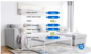 [Alarm record]: Options include: video and snapshot. Recording means when an alarm is triggered, indoor monitor with SD card automatically starts recording until alarm ends or the user manually stops by pressing hang up button. Snapshot means when an alarm is triggered, indoor monitor with SD card will automatically take a picture of sensor camera device. The user can also manually press setting button for continuous snapshots.

 NOTE:
NOTE:


ALARM INSTRUCTION
- The final public terminal is shorted to ground to activate the alarm, and indoor monitor speaker rings. During this period, press to stop alarming and enter standby
- When in recording mode, 120s continuously display and record the During this period, press to stop alarm and enter standby mode.
- When in snapshot mode, a photo is taken at the beginning of alarm, and the image is continuously displayed within During this period, press to stop the alarm and enter standby mode.
Alarm Sensor Wiring Diagram :
- Suitable for connecting two normally closed (NC) or normally open (NO) alarm 2 alarm input channels without input limitation (can be normally open or normally closed).
- The ALM terminal of alarm sensor is connected to ALM terminal of indoor monitor (the alarm sensor is powered by external power supply).
- Alarm sensor GND terminal is connected to camera GND.
- For NO alarm input, when GND and ALM are connected, the alarm will be triggered.
- For NC alarm input, when GND and ALM are off, the alarm will be triggered.
- Suitable for any alarm sensor.
INDOOR MONITOR INSTALLATION
Note: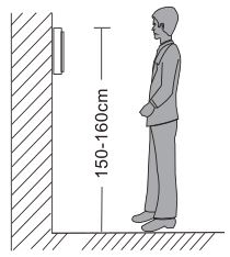
- Please stay away from strong radiation equipment: TV, DVR, etc.
- Please do not disassemble without permission to avoid electric shock.
- Do not drop, shake or strike the device, otherwise the components will be damaged.
- Select the best position for installation, and the distance from the horizontal view is 150cm.
- Please shut down before installation.
- Keep a distance of more than 30 cm from the AC power source to avoid interference.
- Keep away from water, magnetic fields and chemicals. Please turn off the power before installation.
How to install indoor monitor
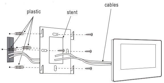
SPECIFICATIONS
ACCESSORIES

Statement
- If there is any doubt or disputable regarding information in this manual, you can call our company for clarification.
- There maybe some difference between the description provided here and the actual devices, as our products are constantly developing and upgrading. We apologize if this manual does not contain all of the latest updates. Thanks
MC-0310 V4.0
WiFi Video Intercom System Indoor Monitor User Manual – WiFi Video Intercom System Indoor Monitor User Manual –
[xyz-ips snippet=”download-snippet”]