Valor HomeFlame Super 470MN Gas-Fired
Vented Room Heater User Manual
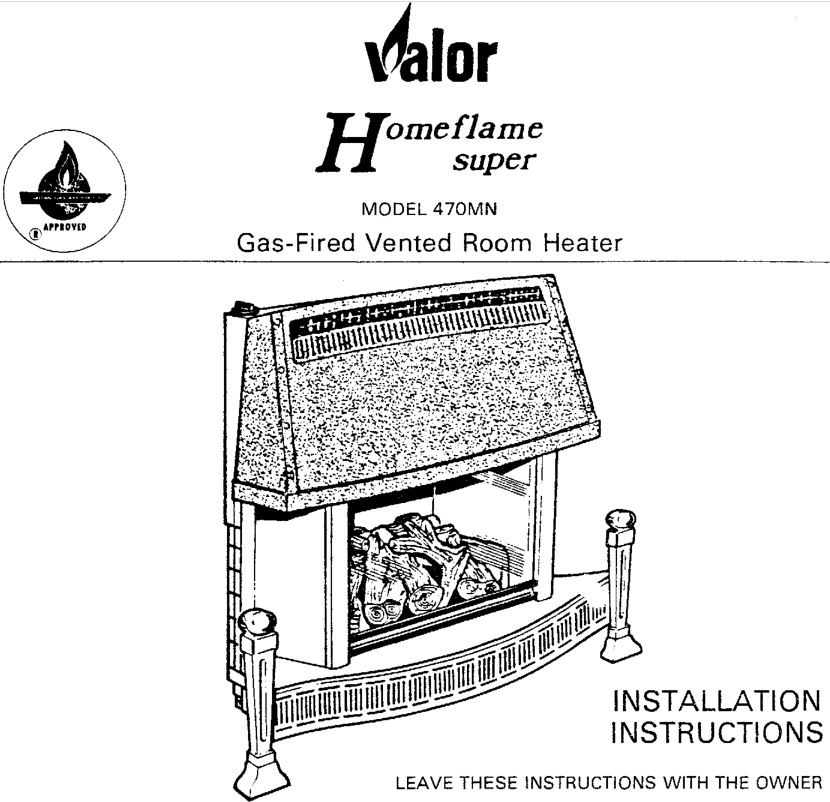
THIS HEATER IS FOR USE WITH NATURAL GAS ONLY
FOR YOUR SAFETYDo not store or use gasoline or other flammable vapors and liquids in the vicinity of this or any other appliance.
If you smell gas:
- Open windows.
- Turn off main gas supply.
- Don’t touch electrical switches.
- Extinguish any open flame.
- Immediately call your gas supplier.
![]()
INSTALLATION INSTRUCTIONS
GENERAL
Installation must conform with local codes or, in the absence of local codes, with the current CAN 1-B149.1 Installation Code. (Natural Gas)
CLEARANCES
Make sure that minimum clearances to combustible materials are maintained during installation including adequate space for the proper operation and servicing of the heater. The minimum clearances from the heater to combustibles are shown below (Fig. 1 ).
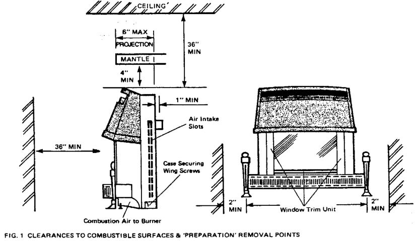
NOTE: Ensure that the combustion air opening under the heater is not obstructed.
FLOOR
DO NOT place heater on Carpeting, Vinyl or other soft-surfaced floor coverings. Install only on hard surfaced materials. It is recommended for aesthetic considerations and ease of maintenance that the HOMEFLAME SUPER be installed on a hearth finished with brick, ceramic tile, marble etc. Raising the hearth slightly will help to minimize dust and lint accumulation under the unit.
DRAFT HOOD
The HOMEFLAME has a draft hood built into its back and draws its air from either side. It must not be altered or obstructed, and the unit must be installed so that the draft hood is in the same atmospheric pressure zone as the combustion air inlet to the burner.
VENTING
The HOMEFLAME SUPER is a vented appliance and must be connected to a chimney/flue in accordance with the code.
For your added safety this heater is equipped with a vent safety switch designed to sense incorrect venting and react by shutting down the gas supply. This thermally actuated switch is located within the draft hood so as to detect either a blocked chimney condition or backdraft condition where the chimney flow has reversed due to any cause. (See section 3.3)
A venting adaptor kit for a concealed wall venting system is itemized in Section 4.
GAS
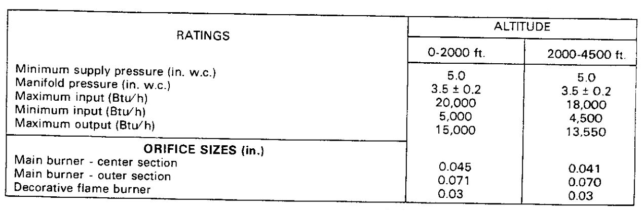
For use with natural gas only. The minimum gas inlet pressure in 5″ water column.
PREPARATION
UNPACKING
The HOMEFLAME SUPER is packed assembled, except for the ceramic logs, ceramic grids, log support bars, ceramic side cheeks and flue collar, all of which are in a separate styrofoam package within the main carton.
GREAT CARE SHOULD BE TAKEN IN REMOVING THE CONTENTS FROM THE CARTON TO PREVENT DAMAGE.
PREPARE THE HOMEFLAME SUPER by standing it upright are:
- Remove the window trim unit (Fig. 1) by grasping the ‘brass’ side trims and pushing upwards to clear their locations. Lift clear of the casing and remove.
- Unscrew the two case securing screws (one either side) located in the recesses near the bottom rear of the outer casing sides (see fig 1)
- Lift the outer casing assembly clear and place safely to one side.
- Remove the window frame by releasing the two side catches and lifting the frame clear of its bottom location. Place the window frame safely to one side.NOTE: The white baseboard in the radiant box must be left in place – it is not packing material.
- Fit the flue collar to the back of the heater using the self tapping screws provided.
- Level the unit by slacking off the lock nuts, and turning the levelling screws up or down as required with the screw heads bearing on the floor plate. Ensure that the unit is square to the wall and level then tighten the lock nuts.
Gas connection is 3/8″ NPT and is on the right hand side. After making the gas connection, test for leaks with soapy solution.
Connect the flue outlet to the venting system (see section 4 for specifics).
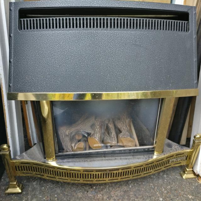
ASSEMBLE THE LOGS
In order to obtain the correct performance from your heater, the Ceramic Grids and Logs must be positioned as in these instructions.The Ceramic Grids are handed. Each Log has a number stamped on it which corresponds with the number referred to in these instructions. WHEN IN POSITION THE NUMBERS ON THE LOGS FACE DOWN.
- POSITION OF SIDE CHEEKS & SUPPORT RODS
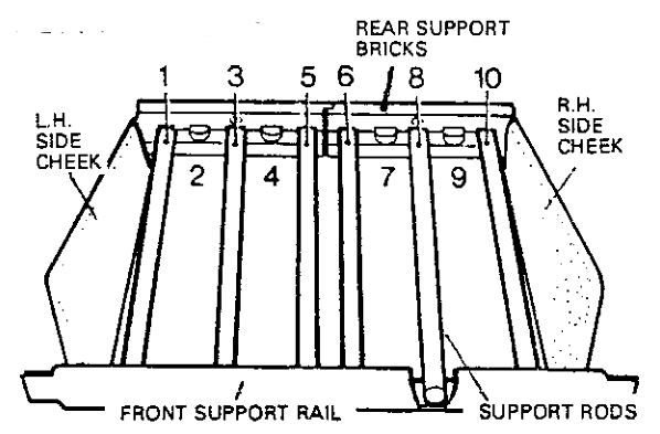
 Make sure the side cheeks are in position and that 6 ceramic support rods are positioned in the correct slots in the rear support bricks and front support rail. Counting from the left side, the rods should be located in slot numbers 1, 3, 5, 6, 8 & 1 0. Make sure the rods are not broken.
 - POSITION THE CERAMIC GRIDS The grids are handed.The left hand grid must be positioned so that its long ‘finger’ is at the front of the fire bed and points to the right. The locating lugs on the underside of the ·grid must drop in place at the right side of the second support rod from the left.The right hand grid must be positioned so that it is a mirror image of the left hand grid, i.e., the long ‘finger’ must be at the front of the fire bed and pointing to the left. The locating lugs on the underside of the grid must drop in place at the left side of the fifth rod from the left.When assembled, the ‘fingers’ will touch in the center.
- POSITION LOG No. 1 Place Log No. 1 at the rear of the ceramic grids. The largest decorative stump on the log should be on the left hand side and the log should be as far to the left as possible.
- POSITION LOG No. 2 Place Log No 2 at the left side of the bed. Slide the wedge shaped end under the top lip of the metal front support rail and to the left of the ceramic grid. The left hand stump of the T shaped branch at the rear should be over the left side cheek and touch the bright metal side of the firebox.
- POSITION LOG No. 3 Place log No 3 at the right side of the bed. Slide the wedge shaped end under the top lip of the metal front support rail and to the right of the ceramic grid. The right hand end of the T shaped branch at the rear should be over the right side cheek and touch the bright metal side of the fire box.
- POSITION LOG No. 4 Place log No 4 in the center of the fire bed with the wide end at the front. The two location lugs underneath the log should drop between the two center support rods. The bottom front edge of the log must be BEHIND THE ‘fingers’ at the front of the ceramic grids and NOT on top of the grids. The base of the log should rest directly on the support bars. The narrow rear portion should be over log No. 1.
- POSITION LOG No. 5 Place log No 5 between No 2 and log No 4. The arm with three branches should point to the rear center with the right hand branch resting inside the comma shaped seating on the top of log No 4. The left hand branch should rest against the right hand of the rear T section of log No 2 and be pushed down to touch the rear log (No. 1 ). The branch at the front of the log should rest against the front right hand piece of log No 2 and its right hand edge (pointing to the front center of the bed) should touch the front left side of the center log (No. 4).
- POSITION LOG No. 6 Place log No 6 between log No 3 and log No 4. The joined section of the two branches should be at the front. Slide the long thin branch underneath the small stump at the right hand side of the center log (No 4) so that it is pointing towards the rear center of the bed. The lug underneath the front (jointed) part of the log should drop into the front hole in the ceramic grid.
 Make sure the side cheeks are in position and that 6 ceramic support rods are positioned in the correct slots in the rear support bricks and front support rail. Counting from the left side, the rods should be located in slot numbers 1, 3, 5, 6, 8 & 1 0. Make sure the rods are not broken.
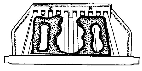 The grids are handed.The left hand grid must be positioned so that its long ‘finger’ is at the front of the fire bed and points to the right. The locating lugs on the underside of the ·grid must drop in place at the right side of the second support rod from the left.The right hand grid must be positioned so that it is a mirror image of the left hand grid, i.e., the long ‘finger’ must be at the front of the fire bed and pointing to the left. The locating lugs on the underside of the grid must drop in place at the left side of the fifth rod from the left.When assembled, the ‘fingers’ will touch in the center.
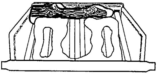 Place Log No. 1 at the rear of the ceramic grids. The largest decorative stump on the log should be on the left hand side and the log should be as far to the left as possible.
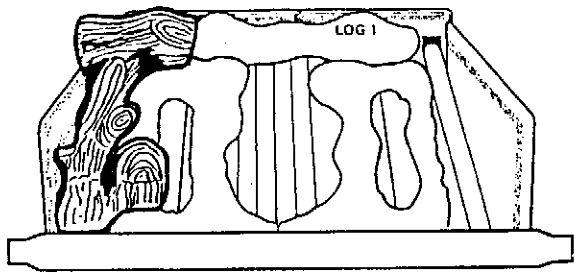 Place Log No 2 at the left side of the bed. Slide the wedge shaped end under the top lip of the metal front support rail and to the left of the ceramic grid. The left hand stump of the T shaped branch at the rear should be over the left side cheek and touch the bright metal side of the firebox.
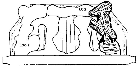 Place log No 3 at the right side of the bed. Slide the wedge shaped end under the top lip of the metal front support rail and to the right of the ceramic grid. The right hand end of the T shaped branch at the rear should be over the right side cheek and touch the bright metal side of the fire box.
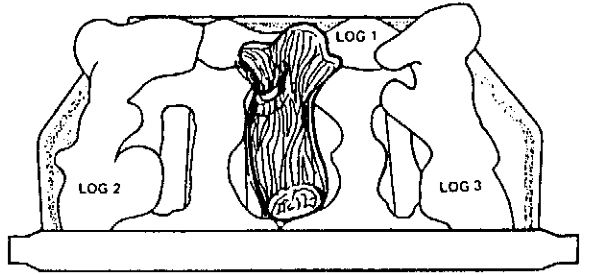 Place log No 4 in the center of the fire bed with the wide end at the front. The two location lugs underneath the log should drop between the two center support rods. The bottom front edge of the log must be BEHIND THE ‘fingers’ at the front of the ceramic grids and NOT on top of the grids. The base of the log should rest directly on the support bars. The narrow rear portion should be over log No. 1.
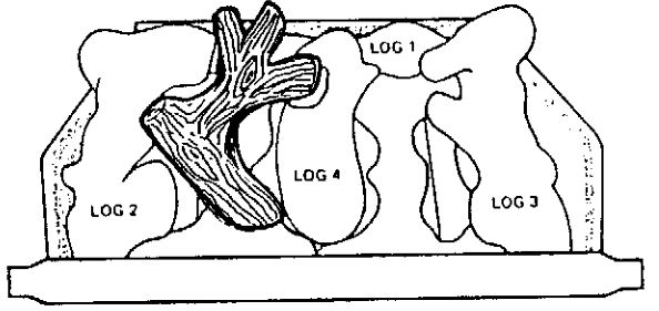 Place log No 5 between No 2 and log No 4. The arm with three branches should point to the rear center with the right hand branch resting inside the comma shaped seating on the top of log No 4. The left hand branch should rest against the right hand of the rear T section of log No 2 and be pushed down to touch the rear log (No. 1 ). The branch at the front of the log should rest against the front right hand piece of log No 2 and its right hand edge (pointing to the front center of the bed) should touch the front left side of the center log (No. 4).
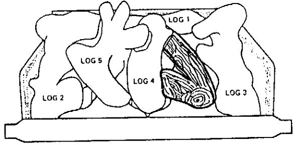 Place log No 6 between log No 3 and log No 4. The joined section of the two branches should be at the front. Slide the long thin branch underneath the small stump at the right hand side of the center log (No 4) so that it is pointing towards the rear center of the bed. The lug underneath the front (jointed) part of the log should drop into the front hole in the ceramic grid.
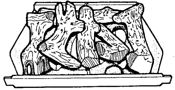
THE CORRECTLY ASSEMBLED LOG BASKET SHOULD APPEAR AS SHOWN HERE
REPLACE THE GLASS WINDOW AND FRAME
COMMISSIONING
CHECK OPERATION OF CONTROLS
- IGNITIONIgnition is by piezo-electric spark produced by the igniter push button adjacent to the control knob on top of the heater. NOTE: The small hole in the piezo-unit clamp bracket is equivalent to the control indicator mark on the outer casing. To ignite
- Push in and turn the control knob counter-clockwise to the 1/IGN position. Hold the control knob down as far as it will go and wait for a few seconds.
- While still holding down the control knob, press the igniter button several times.
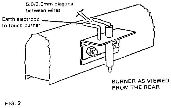
- Continue to hold down the control knob for a further five seconds, on releasing the control knob the heater should remain alight on low setting (main burner center section). If the burner does not ignite after ensuring that the air has been purged, check that the electrode gap is set as shown in Fig. 2.
- Check all the control settings. (Turn counterclockwise for progressive settings). These are:- OFF: Depress the Knob slightly turn clockwise to OFF and release Knob. If any resistance is experienced at the 1/IGN position release the Knob before turning to OFF.
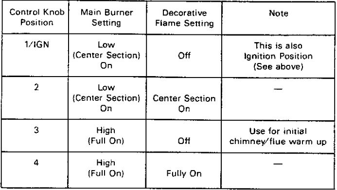 OFF: Depress the Knob slightly turn clockwise to OFF and release Knob. If any resistance is experienced at the 1/IGN position release the Knob before turning to OFF.
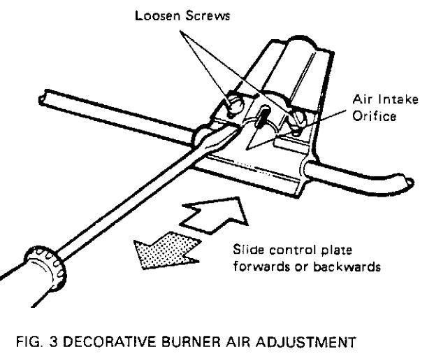
DECORATIVE FLAME ADJUSTMENTS (fig. 3)
The decorative flame burner may need adjusting to suit the local supply gas. The adjustment procedure is as follows:-
- Light the pilot and turn to setting number 4.
- Leave on for 15 minutes.
- Loosen the slotted screws fixing the air intake control plates located on the decorative flame burner nozzles.
- Adjust the air intake by sliding the control plates forward or back using the tip of the screwdriver to give the correct flame pattern. There should be no appreciable deposit of carbon on the logs.
- Retighten the screws.
Check the Gas Pressure
Main burner aeration is non adjustable. The unit is pre-set to give the correct heat input on Natural Gas at the inlet pressure shown below. The burner manifold pressure is controlled by a regulator and should be checked at the pressure test point which is located immediately downstream of the regulator. The pressure check should be carried out with the unit burning and the control knob setting at 4. The pressure setting should be within the limits as shown below. If in doubt – check gas rate at meter after 10 minutes of operation at maximum (Control position 4)
Test for flue spillage.
A “spillage” test must be made before the installed appliance is left with the customer. Carry it out in the following manner before replacing the outer casing.
- Close all doors and windows in the room/start exhaust fans in home.
- Light the unit and set controls at full fire (position 4).
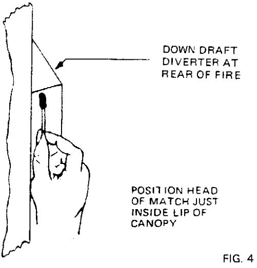
- After a few minutes, test with a smoke match that there is “pull” on the edge of the draft diverter (see Fig. 4). If the flue is blocked, or has strong reverse flow, the thermally actuated safety switch mounted in the draft diverter opening, will automatically shut of the gas supply within about 5 minutes.
- If the heater turns off because of spillage, wait 10 minutes and try again. If the smoke is still not drawn into the draft diverter, turn the unit off and check the cause of lack of draft. If necessary, seek expert advice.
COMPLETE THE ASSEMBLY
- Re-locate the 01… casing assembly over the unit. Re-fit the screws in the bottom sides oft he case. Make sure that the casing sides are located outside of the back panel.
- Adjust the brass andirons at the front of the casing by slackening the Pozi-driv screw behind each one and ensuring that the foot of the andiron rests on the floor. Re-tighten the screws.
- Replace the window trim assembly. (Note: This assembly cannot be fitted unless the window frame side catches are correctly located).
FINAL OPERATION CHECK:
Check that the heater is square with the wall and level.Re-check the ignition and operate the heater on all settings.
MAKE SURE THAT THE USER KNOWS THAT:
- The control knob must be pressed in before turning counter-clockwise.
- To light the heater the control knob must be turned to 1/IGN position and the ignition button depressed. Explain lighting sequence, and how to turn off.
- The heater can be lit with a taper if necessary.
- In the event of the glass front panel being damaged the heater should be turned off and not used until the glass is replaced.
- The window frame can be removed to re-set the logs if necessary but must be placed back in position. (Explain how to remove the window frame).
- The fire may smell slightly for a period due to its newness.
- It is recommended that the fire be serviced at least once a year.
- The suppy system has a shut-off valve. (point out its location)
HAND OVER THE INSTRUCTION BOOKLETS TO THE OWNER.
VENTING CONNECTIONS
VENTING INTO SOLID FUEL BURNING FIREPLACES
- The HOMEFLAME SUPER may be connected to the chimney of a solid fuel fireplace that has been built and installed in accordance with the provincial or territorial building code recognized by the authority having jurisdiction, or in the absence of such a code, then in accordance with the National Building Code of Canada.
- Prior to installation, the chimney must be swept and checked for soundness.
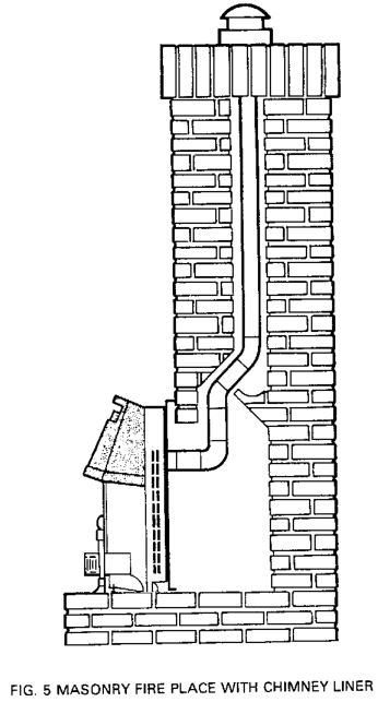
- Install an approved chimney liner not larger than 4″ diam. Use only a flue liner that is approved by the enforcing authority, and that is installed in accordance with the manufacturers instructions. If a flexible liner system is used, ensure that no sags or dips are allowed to occur where the liner connects to the heater. (Fig. 5).
CONCEALED WALL VENT SYSTEM TYPE B VENT
DESCRIPTION
Part # 400 CONCEALED VENTING KIT allows the appliance to be installed with a Type B metal vent concealed behind a wall or partition ancVor in a chase. The venting kit is designed for a 4″ round flue, the kit is shown below (fig 6).

FRAMING
Using standard 2 x 4 construction, frame an opening for the framing plates allowing adequate depth behind the framing for the flue adaptor box and B Vent (minimum depth of enclosure from room side of framing to combustibles behind flue adaptor box is 12″). Framing dimensions for the opening are 20″ wide by 24¾” high above the finished hearth* level.
NOTE: This heater has been approved for installation on a hard surface combustible floor but it is recommended for aesthetic purposes and ease of maintenace that the heater be installed on a hearth finished with brick, ceramic tile, marble etc. Raising the hearth slightly will help to minimize dust and lint accumulation under the unit. Minimum hearth dimensions are 12″ out from the framing plate by 32″ wide. DO NOT PLACE THE HEATER ON VINYL FLOORING OR CARPET.
CLEARANCE TO COMBUSTIBLES
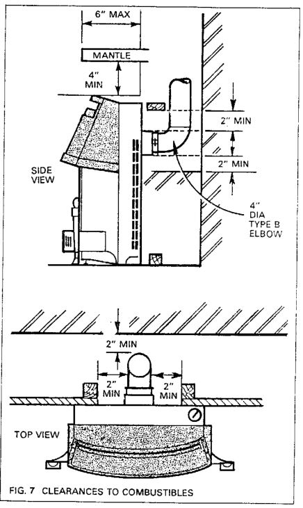
When installed, the minimum clearances to combustibles are shown below: (Fig. 7)
NOTE – CLEARANCES TO COMBUSTIBLES
Outside edges of framing plate O”.Any part of the Flue Adapter Box 2″
Clearance to the connecting elbow is determined by the 8149 Installation Code or the authority having jurisdiction.
ATTACHMENT OF FRAMING PLATES & B VENT
- Attach the bottom framing plate to the framing using 5 – # 8 x 1 ¼” wood screws. The bottom edge of the framing plate should be level with the top of the floor or hearth.
- Place the top framing plate and flue adaptor box above the bottom plate and attach with 5 – # 8 x 1 ¼” wood screws.
- Connect 4″ Type B Vent Elbow to the outlet on the flue adaptor box and fasten securely using the clamping band.
FINAL FITTING OF THE HOMEFLAME
With the floor or hearth finished to its final elevation, push the heater in place and check alignment of the flue collar with the sealing plate. Adjust the sealing plate height, if necessary, by loosening the sealing plate fixing screws and sliding the plate up or down as required (Maximum adjustment 9/ 1s”). Tighten the screws after adjusting. Replace the Heater against the framing plates with the flue collar fully through the sealing plate and proceed with gas piping, log assembly and start up as per instruction sections 2 & 3.
OPTIONAL POWER VENT CONVERSION KIT PART # 500PVC)
An approved power vent conversion kit is available for use when a conventional chimney is not practical. Ask your Dealer for full details.
Valor HomeFlame Super 470MN Gas-Fired Vented Room Heater User Manual – Valor HomeFlame Super 470MN Gas-Fired Vented Room Heater User Manual –
[xyz-ips snippet=”download-snippet”]