Read and understand this manual and all safety signs before using this appliance. Keep this manual for future reference.
DESCRIPTION
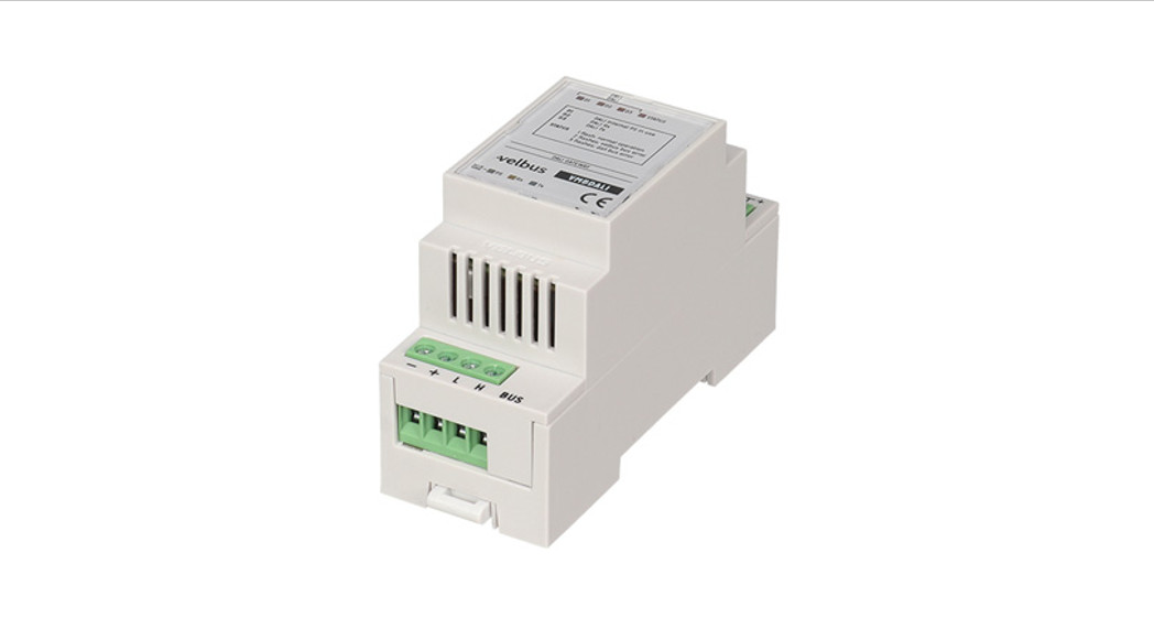
Velbus-DALI Gateway with built-in DALI power supply
USE AND CONFIGURATION
Use the VMBDALI to control a DALI device or bus system through the Velbus home automation system.
- Connect the Velbus bus and DALI bus (fig. 1).
- If no other DALI power supply is present, activate the VMBDALI internal DALI power supply. To do so, load the VMBDALI configuration page in the VelbusLink configuration software. Caution: 1 DALI bus may only contain 1 active DALI power supply. Make sure that no other DALI power supply is activated prior to activating the VMBDALI internal DALI power supply.
- Configure the DALI devices in VelbusLink (on the configuration page of the VMBDALI).
- Create actions between the VMBDALI channels and other Velbus channels in
VelbusLink.(See installation guides on www.velbus.eu for more general information about Velbus.) STATUS LEDs:
- PS LED: Velbus power supply voltage detected
- Rx LED: Velbus CAN bus packet received
- Tx LED: Velbus CAN bus packet sent
- D1: Internal DALI power supply enabled
- D2: DALI packet received
- D3: DALI packet sent
STATUS:
- 1 x flash: normal operation
- 2 x flash: Velbus bus communication error
- 3 x flash: DALI bus communication error
CONCISE TECHNICAL SPECIFICATIONS
Compatible with DALI and DALI-2Supply voltage: 15 ± 3 VDCMax. current consumption
- internal DALI power supply enabled: 300 mA
- internal DALI power supply disabled: 50 mA
DIN width: 2 modulesControls up to 64 DALI devices, 16 groups, and 16 scenes.Thermal and short-circuit protection.For a detailed list with technical specifications, please refer to the product page on www.Velleman.EUCIRCUIT DIAGRAMSee fig. 1

![]() This product complies with all of the relevant European guidelines and regulations.
This product complies with all of the relevant European guidelines and regulations.
Velbus – Legen Heirweg 33, BE-9890 Gavere, Belgium – tel. +32 9 384 36 11 – e-mail: [email protected] – www.velbus.eu
References
[xyz-ips snippet=”download-snippet”]

