
velleman Ammeter Clamp CAT III 600 V
![]()

USER MANUAL
1. Introduction
To all residents of the European Union Important environmental information about this product![]() This symbol on the device or the package indicates that disposal of the device after its lifecycle could harm the environment. Do not dispose of the unit (or batteries) as unsorted municipal waste; it should be taken to a specialized company for recycling. This device should be returned to your distributor or to a local recycling service. Respect the local environmental rules.If in doubt, contact your local waste disposal authorities.Thank you for choosing Velleman! Please read the manual thoroughly before bringing this device into service. If the device was damaged in transit, do not install or use it and contact your dealer.
This symbol on the device or the package indicates that disposal of the device after its lifecycle could harm the environment. Do not dispose of the unit (or batteries) as unsorted municipal waste; it should be taken to a specialized company for recycling. This device should be returned to your distributor or to a local recycling service. Respect the local environmental rules.If in doubt, contact your local waste disposal authorities.Thank you for choosing Velleman! Please read the manual thoroughly before bringing this device into service. If the device was damaged in transit, do not install or use it and contact your dealer.
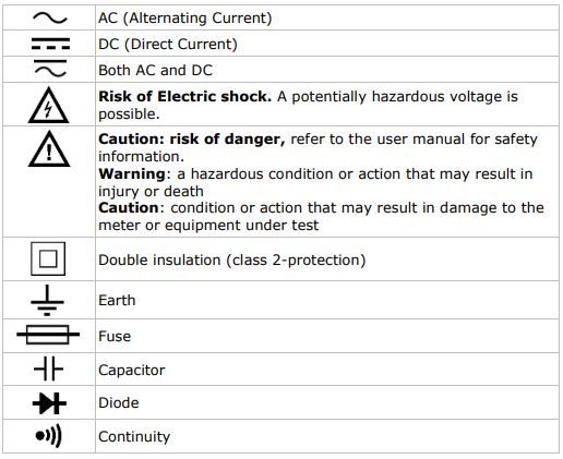
2. Used Symbols
3. General Guidelines
Refer to the Velleman® Service and Quality Warranty on the last pages of this manual.

4. Maintenance
![]() There are no user-serviceable parts inside the device. Refer to an authorized dealer for service and/or spare parts. Before performing any maintenance activities, disconnect the test leads from the jacks. For instructions on replacing the battery or fuse, refer to §11 Battery and fuse replacement. Do not apply abrasives or solvents to the meter. Use a damp cloth and mild detergent for cleaning purposes.
There are no user-serviceable parts inside the device. Refer to an authorized dealer for service and/or spare parts. Before performing any maintenance activities, disconnect the test leads from the jacks. For instructions on replacing the battery or fuse, refer to §11 Battery and fuse replacement. Do not apply abrasives or solvents to the meter. Use a damp cloth and mild detergent for cleaning purposes.
5. During Use
![]() Risk of electric shock during operation. Be very careful when measuring live circuits.
Risk of electric shock during operation. Be very careful when measuring live circuits.
- Never exceed the limit value for protection. This limit value is listed separately in the specifications for each range of measurement.
- Do not touch unused terminals when the meter is linked to a circuit, which is being tested.
- Never use the meter with CAT III installations when measuring voltages that might exceed the safety margin of 600 V above earth ground.
- Set the range selector at its highest position if the intensity of the charge to be measured is unknown beforehand.
- Disconnect the test leads from the tested circuit before rotating the range selector in order to change functions.
- When carrying out measurements on a TV set or switching power circuits, always remember that the meter may be damaged by any high amplitude voltage pulses at test points.
- Always be careful when working with voltages above 60 VDC or 30 VAC RMS. Keep your fingers behind the probe barriers at all times during measurement.
- Never perform resistance, diode, or continuity measurements on live circuits. Make sure all capacitors in the circuit are depleted.
- Always hold the device behind the finger guard (see General Description, nr. 12).
- Comply with the local and national safety regulations. Use personal protective equipment, such as approved rubber gloves, face protection, and flame-resistant clothing, to prevent shock and arc blast injury where hazardous live conductors are exposed.
- Do not use this device to measure a current with a frequency above 1 kHz.
- Only use this device as specified in this manual in order not to compromise the protection supplied by the device.
6. General Description
Refer to the illustration on page 2 of this manual:
- Clamp jaws
- Clamp trigger
- Selection button
- M-hold button
- D-hold button
- Selection switch
- Display 3 ½ digits
- “COM” jack Insert the black (negative) test lead.
- “VΩ
 ” jackInsert the red (positive) test lead in this connector to measure voltage, resistance, and frequency.
7. Overvoltage/Installation Category
DMMs are categorized depending on the risk and severity of transient overvoltage that might occur at the point of the test. Transients are short-lived bursts of energy induced in a system, e.g. caused by a lightning strike on a power line.
The existing categories according to EN 61010-1 are:CAT IA CAT I-rated meter is suitable for measurements on protected electronic circuits that are not directly connected to mains power, e.g. electronics circuits, control signals…
CAT IIA CAT II-rated meter is suitable for measurements in CAT I environments and mono-phase appliances that are connected to the mains by means of a plug and circuits in a normal domestic environment, provided that the circuit is at least 10 m apart from a CAT III- or 20 m apart from a CAT IV-environment. E.g. household appliances, portable tools…
CAT IIIA CAT III-rated meter is suitable for measurements in CAT I- and CAT II-environments, as well as for measurements on (fixed) mono or poly-phased appliances which are at least 10 m apart from of a CAT IV environment, and for measurements in or on distribution level equipment (fuse boxes, lighting circuits, electric ovens).
CAT IVA CAT IV-rated meter is suitable for measuring in CAT I-, CAT II- and CAT III environments as well as on the primary supply level. Note that for all measurements on equipment for which the supply cables run outdoors (either overhead or underground) a CAT IV meter must be used.
Warning:This device was designed in accordance with EN 61010-1 installation category CAT III 600 V. This implies that certain restrictions in use applications are related to voltages and voltage peaks which can occur within the environment of use. Refer to the table above.
![]() This device is only suitable for measurements up to 600 V in CAT III
This device is only suitable for measurements up to 600 V in CAT III
8. Pollution Degree
IEC 61010-1 specifies different types of pollution environments, for which different protective measures are necessary to ensure safety. Harsher environments require more protection, and the protection against the pollution which is to be found in a certain environment depends mainly on the insulation and the enclosure properties. The pollution degree rating of the DVM indicates in which environment the device may be used.
Pollution degree 1No pollution or only dry, nonconductive pollution occurs. Pollution has no influence. (only to be found in hermetically sealed enclosures)
Pollution degree 2Only non-conductive pollution occurs. Occasionally, temporary conductivity caused by condensation is to be expected. (home and office environments fall under this category)
Pollution degree 3Conductive pollution occurs, or dry non-conductive pollution occurs that becomes conductive due to condensation that is to be expected. (industrial environments and environments exposed to outside air – but not in contact with precipitation)
Pollution degree 4The pollution generates persistent conductivity caused by conductive dust or by rain or snow. (exposed outdoor environments and environments where high humidity levels or high concentrations of fine particles occur)
Warning: This device was designed in accordance with EN 61010-1 pollution degree 2. This implies that certain restrictions in use applications are related to the pollution which can occur within the environment of use. Refer to the table above.![]() This device is only suitable for measurements in Pollution degree class 2 environments.
This device is only suitable for measurements in Pollution degree class 2 environments.
9. Specifications
This device is not calibrated when purchased!Regulations concerning the environment of use:Use this meter only for measurements in CAT I, CAT II, and CAT III environments (see §7).Use this meter only in a pollution degree 2 environment (see §8).Ideal working conditions include:temperature: 0 °C to 40 °C (32 °F to 104 °F)relative humidity: max. 80 %altitude: max. 2000 m (6560 ft)
voltage ………………………………………………………………… 600 Vpower supply ………………………………… 3 x 1.5 V AAA/LR03 (incl.)display…………………………………………………… LCD, 1999 countsdisplay dimensions …………………………………………… 18 x 39 mmover-range ………………………………………………………………..yescontinuity buzzer …………………………………………………………yesdiode test………………………………………………………………….yeslow-battery indication …………………………………………………..yesranging mode ………………………………………………… auto/manualdata hold ………………………………………………………………….yesbacklight ……………………………………………………………………..–auto power-off ……………………………………………………………yesdimensions …………………………………………131.5 x 61 x 24.8 mmweight (with battery) …………………………………………………135 gstorage environmenttemperature …………………………………………. -20 °C to 60 °Chumidity …………………………………………………… < 90 % RH test lead probe……. CAT III 1000 V / CAT IV 600 V, 10 A; L = 84 cm
9.1 AC + DC VOLTAGE
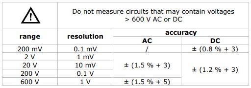
Impedance: 10 MΩFrequency range: 40 Hz-400 Hz, 40 Hz-100 Hz on 600 V range
9.2 AC CURRENT

Average sensing calibrated to RMS of sine waveFrequency response: 50 Hz-60 HzOverload protection: 600 A RMS within 60 sec
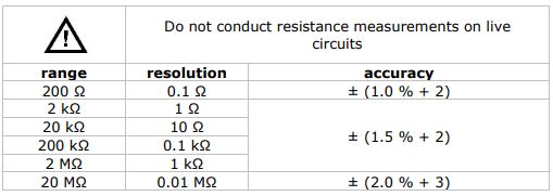
9.3 RESISTANCE
Overload protection: 250 V DC or AC RMS
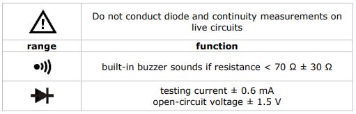
9.4 DIODE + AUDIBLE CONTINUITY
 Overload protection: 250 V DC or AC rms
10. Operation
10.1 VOLTAGE MEASUREMENT
![]() Do not measure circuits that may contain voltages > 600 V AC or DC
Do not measure circuits that may contain voltages > 600 V AC or DC![]() Use extreme caution when measuring voltages higher than 60 VDC or 30 VAC RMS. Always place your fingers behind the protective edges of the test probes while measuring!
Use extreme caution when measuring voltages higher than 60 VDC or 30 VAC RMS. Always place your fingers behind the protective edges of the test probes while measuring!
- Connect the black test lead to the “COM” jack and the red test lead to the “VΩ ” jack.
- Set the selection switch to the desired “ ” position.
- Press the selection button to choose the AC or DC voltage measurement.
- Connect the test leads across the source under measurement.
- Read the voltage value on the LCD display.
10.2 AC CURRENT MEASUREMENT
![]() Do not measure circuits that may contain voltages > 600 V AC or DC
Do not measure circuits that may contain voltages > 600 V AC or DC
![]() Use extreme caution when measuring voltages higher than 60 VDC or 30 VAC RMS.
Use extreme caution when measuring voltages higher than 60 VDC or 30 VAC RMS.
- Set the selection switch to the desired “20A” or “200/500A” position.
- Open the clamp by pressing the clamp trigger and insert the cable (one cable only) to be measured into the jaw.
- Close the clamp and read the current value on the LCD display.
Notes
- Before measurement, disconnect the test leads from the meter.
- On some occasions that the reading is hard to read, press the D-hold button and read the result later.
10.3 RESISTANCE MEASUREMENT
![]() Do not conduct resistance measurements on live circuits. Make sure all capacitors in the circuit are depleted.
Do not conduct resistance measurements on live circuits. Make sure all capacitors in the circuit are depleted.
- Connect the black test lead to the “COM” jack and the red test lead to the “VΩ ” jack.
- Set the selection switch to the desired ” ” position.
- Press the selection button to choose the “Ω” measurement.
- Connect the test leads across the source under measurement.
- Read the value on the LCD display.
Notes
- If the resistance being measured is connected to a circuit, turn off the power and discharge all capacitors before applying the test probes.
- An over-range is indicated by OL.
10.4 DIODE MEASUREMENT
![]() Do not conduct diode measurements on live circuits. Make sure all capacitors in the circuit are depleted.
Do not conduct diode measurements on live circuits. Make sure all capacitors in the circuit are depleted.
- Connect the black test lead to the “COM” jack and the red test lead to the “VΩ ” jack.
- Set the selection switch to the desired ” ” position.
- Press the selection button to choose the “ ” measurement.
- Connect the test leads across the source under measurement.
- Read the value on the LCD display.
10.5 CONTINUITY TEST
![]() Do not conduct continuity measurements on live circuits. Make sure all capacitors in the circuit are depleted.
Do not conduct continuity measurements on live circuits. Make sure all capacitors in the circuit are depleted.
- Connect the black test lead to the “COM” jack and the red test lead to the “VΩ ” jack.
- Set the selection switch to the desired” “position.
- Press the selection button to choose the measurement.
- Connect the test leads to two points of the circuit to be tested. If continuity exists, the built-in buzzer will sound.
10.6 AUTO POWER OFF
When the meter has been turned on 15 minutes without any activity, the meter will automatically switch off.
10.7 DATA HOLD
Press the D-hold button to lock the displayed value. Press again to exit.
10.8 MAX HOLD
Press the M-hold button to enter the maximum data hold mode. Press again to exit.
11. Battery Replacement
![]() WARNING: To avoid electrical shock always disconnect the test leads prior to opening the housing. To prevent fire hazards, only use fuses with the same ratings as specified in this manual.Remark: refer to the warning on the battery compartment
WARNING: To avoid electrical shock always disconnect the test leads prior to opening the housing. To prevent fire hazards, only use fuses with the same ratings as specified in this manual.Remark: refer to the warning on the battery compartment![]() There are no user-serviceable parts inside the device. Refer to an authorized dealer for service and/or spare parts.
There are no user-serviceable parts inside the device. Refer to an authorized dealer for service and/or spare parts.![]() Disconnect the test leads from the test points and remove the test leads from the measuring terminals before replacing the batteries or fuses.
Disconnect the test leads from the test points and remove the test leads from the measuring terminals before replacing the batteries or fuses.
- When” -+” is displayed, the battery should be replaced.
- Fuses rarely need replacement and blown fuses almost always result from human error.To replace the battery:
- Switch of the meter.
- Remove the screw at the back of the case and gently open the housing.
- Remove the old battery and insert a new one.
- Close the housing and fasten the screw.Battery: 3x AAA/LR03, make sure to respect the polarity
12. Troubleshooting
If the device acts abnormal while measuring, this means that the internal fuse is defective. Keep in mind that a low battery level could lead to incorrect measurements. Replace the battery on a regular basis. (tip: the reduced luminosity of the backlight/LCD display indicates a low battery level)
Use this device with original accessories only. Velleman NV cannot be held responsible in the event of damage or injury resulting from (incorrect) use of this device. For more info concerning this product and the latest version of this manual, please visit our website www.Velleman.eu. The information in this manual is subject to change without prior notice.
© COPYRIGHT NOTICEThe copyright to this manual is owned by Velleman NV. All worldwide rights reserved. No part of this manual may be copied, reproduced, translated, or reduced to any electronic medium or otherwise without the prior written consent of the copyright holder.
Velleman® Service and Quality WarrantySince its foundation in 1972, Velleman® acquired extensive experience in the electronics world and currently distributes its products in over 85 countries.All our products fulfill strict quality requirements and legal stipulations in the EU. In order to ensure the quality, our products regularly go through an extra quality check, both by an internal quality department and by specialized external organizations. If, all precautionary measures notwithstanding, problems should occur, please make an appeal to our warranty (see guarantee conditions).General Warranty Conditions Concerning ConsumerProducts (for EU):• All consumer products are subject to a 24-month warranty on production flaws and defective material as from the original date of purchase.• Velleman® can decide to replace an article with an equivalent article or to refund the retail value totally or partially when the complaint is valid and a free repair or replacement of the article is impossible, or if the expenses are out of proportion. You will be delivered a replacing article or a refund at the value of 100% of the purchase price in case of a flaw that occurred in the first year after the date of purchase and delivery, or a replacing article at 50% of the purchase price or a refund at the value of 50% of the retail value in case of a flaw occurred in the second year after the date of purchase and delivery.• Not covered by warranty:– all direct or indirect damage caused after delivery to the article (e.g. by oxidation, shocks, falls, dust, dirt, humidity…), and by the article, as well as its contents (e.g. data loss), compensation for loss of profits;– consumable goods, parts, or accessories that are subject to an aging process during normal use, such as batteries (rechargeable, non-rechargeable, built-in or replaceable), lamps, rubber parts, drive belts… (unlimited list);– flaws resulting from fire, water damage, lightning, accident, natural disaster, etc.…;– flaws caused deliberately, negligently, or resulting from improper handling, negligent maintenance, abusive use or use contrary to the manufacturer’s instructions;– damage caused by a commercial, professional or collective use of the article (the warranty validity will be reduced to six (6) months when the article is used professionally);– damage resulting from an inappropriate packing and shipping of the article;– all damage caused by modification, repair, or alteration performed by a third party without written permission by Velleman®.• Articles to be repaired must be delivered to your Velleman® dealer, solidly packed (preferably in the original packaging), and be completed with the original receipt of purchase and a clear flaw description.• Hint: In order to save on cost and time, please re-read the manual and check if the flaw is caused by obvious causes prior to presenting the article for repair. Note that returning a non-defective article can also involve handling costs.• Repairs occurring after warranty expiration are subject to shipping costs.• The above conditions are without prejudice to all commercial warranties.The above enumeration is subject to modification according to the article (see article’s manual).
Made in PRCImported by Velleman nvLegen Heirweg 33, 9890 Gavere, Belgiumwww.Velleman.eu
References
[xyz-ips snippet=”download-snippet”]