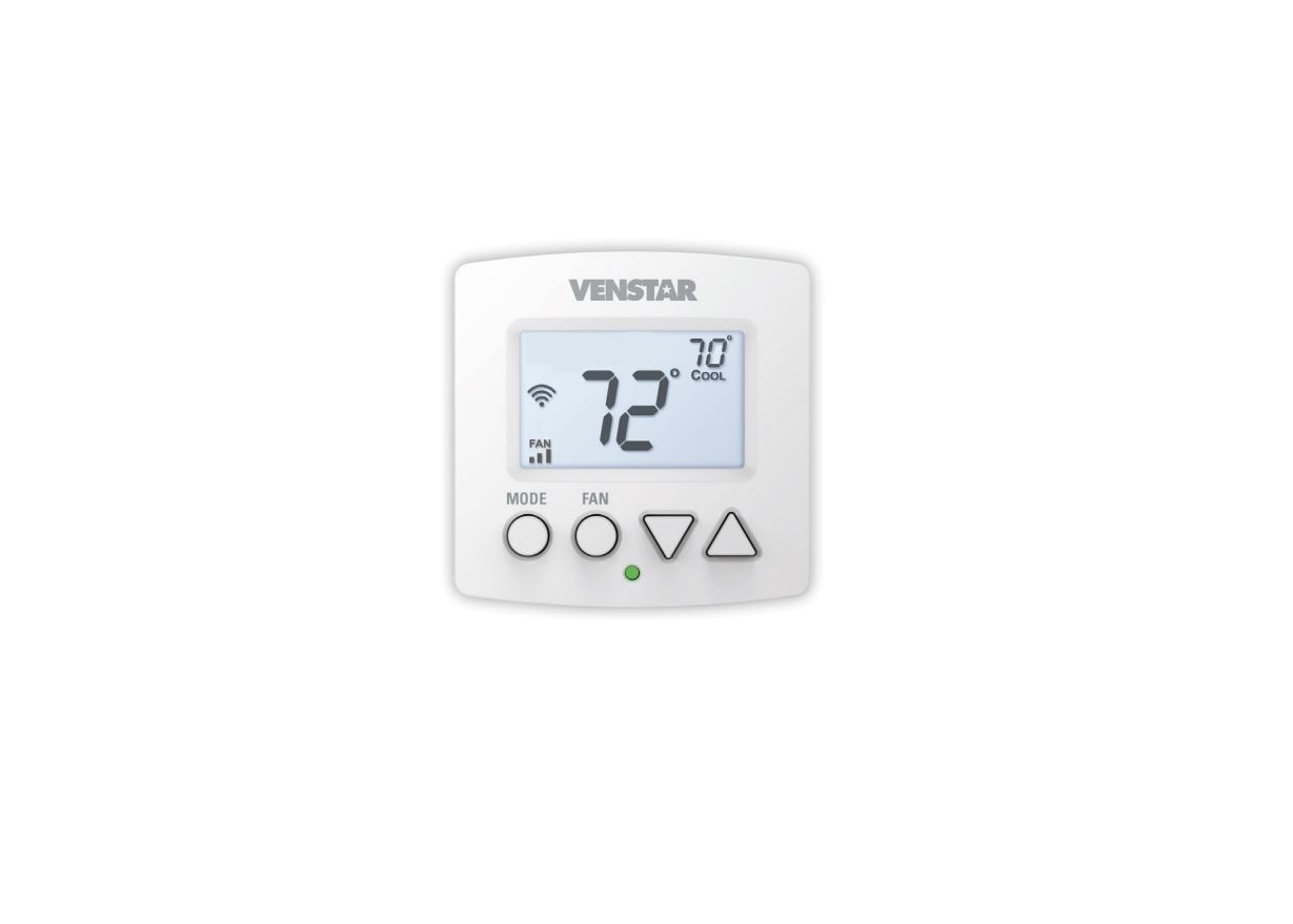
VENSTAR Fan Coil Thermostat T2100 / T2150 User Guide

Thank YouCongratulations and thank you for purchasing your new Ventra Fan Coil thermostat. This guide is intended to help you install and setup the basic features of your thermostat. For a full owner’s manual and installation guide, visit Venstar.com.

Compatibility
Your Venstar EXPLORER Mini® fan coil thermostat is designed to work with 24V fanciless, both 2 pipe or 4 pipe. For 2 pipe units with automatic changeover between heating and cooling based on water supply, you will need to obtain a H2O changeover switch, ACC-SENFC. The thermostat controls 3 speed fans and can control to a remote temperature sensor.
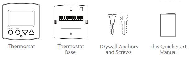
Contents
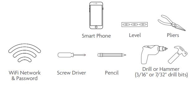
Necessary Tools
Step 1 – Power Off Current System
- All power must be disconnected before any installation or service is attempted. More than one power source may be supplied to a unit. Power to remote mounted control devices may not be supplied through the unit.
- To confirm power is off, adjust the temperature on your current thermostat.

![]() WARNING: Failure to follow this step can result in personal injury and/or death from shock and electrocution.
WARNING: Failure to follow this step can result in personal injury and/or death from shock and electrocution.
Step 2 – Remove Faceplate
Remove the faceplate of current system. Most faceplates snap-off or feature small screws that will need to be removed.

![]() WARNING: If you see large thick electrical wires, wire nuts, or if your system is labeled 120V, 240V, or 277V DO NOT PROCEED. THIS THERMOSTAT IS NOT COMPATIBLE WITH THESE SYSTEMS
WARNING: If you see large thick electrical wires, wire nuts, or if your system is labeled 120V, 240V, or 277V DO NOT PROCEED. THIS THERMOSTAT IS NOT COMPATIBLE WITH THESE SYSTEMS
![]() WARNING: Failure to follow this step can result in personal injury and/or death from shock and electrocution.
WARNING: Failure to follow this step can result in personal injury and/or death from shock and electrocution.
Step 3 – Label & Disconnect Wires

Step 4 – Remove Current Backplate
Unscrew the current backplate and remove it from the wall. Be careful not to let the wires fall into the wall.
TIP: If needed, wrap the wires around a pencil or pen to keep them from falling inside the wall.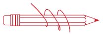
Step 5 – Mount New Base
- Gently separate the display from the base by pulling first from one side, then the other until the two pieces unsnap. A small screwdriver may be used, very carefully, to start separating the two pieces.

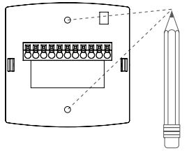
- Position the base against your wall, and determine if wall anchors from current thermostat align with screw locations of new base.
- If base does not align with existing anchor holes, mark new screw locations with a pencil. Drywall: Drill 3/16″ hole for the anchor Plaster: Drill 7/32″ hole for the anchor
- Pull wires through opening in base and secure to the wall using provided screws.

TIP: Use a level to ensure thermostat is properly aligned before marking screw locations.
Step 6 – Connect Wires1) Match your previous wire configuration to the new base. One by one, connect each wire by inserting the metal end into the corresponding slot and tightening the screw.
 TIP: Use pliers to straighten wire before inserting into new base. Be sure to cut any excess wire so that the insulation extends to the terminal block. When the wire is installed properly to the terminal block, there should be no copper exposed.
Step 7 – Attach Thermostat
1) Align the pins on the thermostat circuit board with the corresponding holes below the wiring connectors and push the top and the bottom of the plastic housing enclosing the display until it clicks into place, top and bottom.
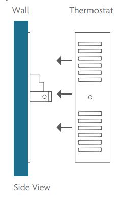
![]() Front of thermostat should click into place easily. If you encounter resistance do not apply excess force remove, check that the pins are straight and ensure there are no wires in the way and retry.
Front of thermostat should click into place easily. If you encounter resistance do not apply excess force remove, check that the pins are straight and ensure there are no wires in the way and retry.
Step 8 – Switch Power/Circuit Breakers Back OnTurn your fancily back on. 6
Step 9 – Set Up Wi-Fi Connection
Overview
At minimum, the first 3 tasks below must be completed to access your thermostat remotely from a browser. The 4th step is optional (highly recommended) and only is needed to access your thermostat(s) from a mobile device.These steps are:
- Successful connection to a local Wi-Fi Access Point with internet access.
- Confirm receipt of a Skyport generated verification email (this only occurs once during the Skyport account setup).
- A 6-digit code obtained from the thermostat is successfully entered into a Skyport account.
- Successfully download and install the Venstar Skyport app on your mobile device(s). Your thermostat operates on the 2.4 Gaz, Wi-Fi b/g/n band.
TABLE OF BUTTON PRESSES TO ENTER MENUS TO ENTER 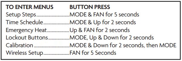
Quick Start – Connect to Wi-Fi
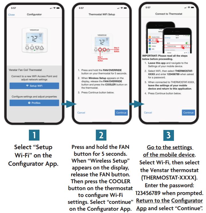
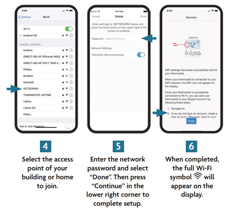
The Explorer thermostats are joined to a Wi-Fi network with the help of the Venstar Configurator App. This app may be downloaded from your mobile device’s app store. Once the thermostat is installed and powered, the Configurator App will facilitate connection to the access point in 6 steps as outlined below.

Scan with mobile device for additional information

Quick Start – Connect to Skyport
Although there is more than one way to create a Skyport account, the steps below illustrate account creation from a browser. To create a Skyport account a thermostat must be joined to the account. If the thermostat is connected to the local Wi-Fi Access Point, but you do not have a Skyport account, you may create an account and join the thermostat to the account by doing the following:
- Open your browser to: http://venstar.skyportcloud.com
- Select “Create account now”Create Account Now
- Follow on screen instructions to create an account and add a thermostat to the Skyport account.
If the thermostat is connected to the local Wi-Fi access point but not yet joined to an existing Skyport account, you may join the thermostat to the account by doing the following:
- Log in to your Skyport account.
- Select the “Location” you want to add a thermostat into.
- Select the “Thermostat tab”.
- Select “+ Add Thermostat”. A screen will `pop-up’ asking for a six digit code.
- Press and hold the fan button on the thermostat for 5 seconds.
- Press the Up button on the thermostat.
- A six digit code will appear on the thermostat’s display.
- Enter the six digit code into your Skyport account.
Skyport will maintain the correct time and day on your thermostat.
If you would like to set up a program/schedule to maintain the desired temperature at various times of the day, you can do this manually at the thermostat or use the Skyport website to enter a time period schedule.
The complete manual is available at venstar.com.
It is much easier to setup the time period program/schedule on the Skyport Web App. To make these adjustments and more to your thermostat from Skyport follow these steps:
- Login to your Skyport account
- Choose the location where your thermostat is installed (the left column)
You may now control the basic functions of the thermostat like MODE, setpoints or fan speed. You can also press on the upper right section of the panel in order to customize the settings.A quick summary of the settings is as follows:Thermostat info – allows you to name the thermostat, view software revisionPermissions – as the owner of this thermostat, you can grant access to other usersRuntimes – view the two week heat or cool runtime of this specific thermostatSensors – view the current and daily min/max values from the internal temperature and any linked wireless sensorsAlerts – view and edit this thermostat’s alerts and setup email notificationsSchedule – view/edit the time period schedule for this thermostatSettings – view/edit all settings within the thermostat (fancily type, setpoint limits, etc.)
 Troubleshooting
Use the following troubleshooting guide to diagnose common problems.

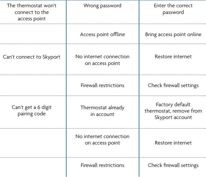
For additional support, contact Technical Support at [email protected].
Warranty
One-Year Warranty – This Product is warranted to be free from defects in material and workmanship. If it appears within one year from the date of original installation, whether or not actual use begins on that date, that the product does not meet this warranty, a new or remanufactured part, at the manufacturer’s sole option to replace any defective part, will be provided without charge for the part itself provided the defective part is returned to the distributor through a qualified servicing dealer.
THIS WARRANTY DOES NOT INCLUDE LABOR OR OTHER COSTS incurred for diagnosing, repairing, removing, installing, shipping, servicing or handling of either defective parts or replacement parts. Such costs may be covered by a separate warranty provided by the installer.
THIS WARRANTY APPLIES ONLY TO PRODUCTS IN THEIR ORIGINAL INSTALLATION LOCATION AND BECOMES VOID UPON REINSTALLATION.
LIMITATIONS OF WARRANTIES ALL IMPLIED WARRANTIES (INCLUDING IMPLIED WARRANTIES OF FITNESS FOR A PARTICULAR PURPOSE AND MERCHANTABILITY) ARE HEREBY LIMITED IN DURATION TO THE PERIOD FOR WHICH THE LIMITED WARRANTY IS GIVEN. SOME STATES DO NOT ALLOW LIMITATIONS ON HOW LONG AN IMPLIED WARRANTY LASTS, SO THE ABOVE MAY NOT APPLY TO YOU. THE EXPRESSED WARRANTIES MADE IN THIS WARRANTY ARE EXCLUSIVE AND MAY NOT BE ALTERED, ENLARGED, OR CHANGED BY ANY DISTRIBUTOR, DEALER, OR OTHER PERSON WHATSOEVER.
ALL WORK UNDER THE TERMS OF THIS WARRANTY SHALL BE PERFORMED DURING NORMAL WORKING HOURS. ALL REPLACEMENT PARTS, WHETHER NEW OR REMANUFACTURED, ASSUME AS THEIR WARRANTY PERIOD ONLY THE REMAINING TIME PERIOD OF THIS WARRANTY.
THE MANUFACTURER WILL NOT BE RESPONSIBLE FOR:
- Normal maintenance as outlined in the installation and servicing instructions or owner’s manual, including filter cleaning and/or replacement and lubrication.
- Damage or repairs required as a consequence of faulty installation, misapplication, abuse, improper servicing, unauthorized alteration or improper operation.
- Failure to start due to voltage conditions, blown fuses, open circuit breakers or other damages due to the inadequacy or interruption of electrical service.
- Damage as a result of floods, winds, fires, lightning, accidents, corrosive environments or other conditions beyond the control of the Manufacturer.
- Parts not supplied or designated by the Manufacturer, or damages resulting from their use.
- Manufacturer products installed outside the continental U.S.A., Alaska, Hawaii, and Canada.
- Electricity or fuel costs or increases in electricity or fuel costs for any reason whatsoever including additional or unusual use of supplemental electric heat.
- ANY SPECIAL INDIRECT OR CONSEQUENTIAL PROPERTY OR COMMERCIAL DAMAGE OF ANY NATURE WHATSOEVER. Some states do not allow the exclusion of incidental or consequential damages, so the above may not apply to you.
This warranty gives you specific legal rights and you may also have other rights which may vary from state to state.
FCC Compliance StatementThis equipment has been tested and found to comply with the limits for an intentional radiator, pursuant to Part 15, subpart C of the FCC rules. These limits are designed to provide reasonable protection against harmful interference in a residential installation. This equipment generates, uses and can radiate radio frequency energy and, if not installed and used in accordance with the instructions, may cause harmful interference in radio communications. However, there is no guarantee that the interference will not occur in a particular installation. If this equipment does cause harmful interference to radio or television reception, which can be determined by turning the equipment off and on, the user is encouraged to try to correct the interference by one or more of the following measures:
- Reorient or relocate the receiving antenna.
- Increase the separation between the equipment and receiver.
- Connect the equipment into an outlet on a circuit different from that of the receiver.
- Consult the dealer or an experienced radio or TV technician for help.
Notice: Only peripherals complying with FCC limits may be attached to this equipment. Operation with noncompliant peripherals or peripherals not recommended by Venstar, is likely to result in interference to radio and TV reception. Changes or modifications to the product, not expressly approved by Venstar could void the user’s authority to operate the equipment.
FCC – INDOOR Mobile Radio Information:
To comply with FCC/IC RF exposure limits for general population / uncontrolled exposure, the antenna(s) used for this transmitter must be installed to provide a separation distance of at least 20 cm from all persons and must not be co-located or operating in conjunction with any other antenna or transmitter.
This Device complies with Industry Canada License-exempt RSS standard(s). Operation is subject to the following two conditions: 1) this device may not cause interference, and 2) this device must accept any interference, including interference that may cause undesired operation of the device.
Under Industry Canada regulations, this radio transmitter may only operate using an antenna of a type and maximum (or lesser) gain approved for the transmitter by Industry Canada. To reduce potential radio interference to other users, the antenna type and its gain should be so chosen that the equivalent isotopically radiated power (e.i.r.p.) is not more than that necessary for successful communication.
 report this ad
We, Venstar, declare under our sole responsibility that the device to which this declaration relates: Complies with Part 15 of the FCC Rules. Operation is subject to the following two conditions: (1) this device may not cause harmful interference, and (2) this device must accept any interference received, including interference that may cause undesired operation.FCC ID: MUH-SKYPORT8IC: 12547A-SKYPORT8![]() Innovation, Science and Economic Development Canada ICES-003 ComplianceLabel: CAN ICES-3 (B)/NM8-3(B)Patents Issued & PendingP/N 88-1366 rev. 1 01/20
Innovation, Science and Economic Development Canada ICES-003 ComplianceLabel: CAN ICES-3 (B)/NM8-3(B)Patents Issued & PendingP/N 88-1366 rev. 1 01/20![]()
References
[xyz-ips snippet=”download-snippet”]