verona Built-in Gas Cooktops

INSTALLATION INSTRUCTIONS
IMPORTANT PLEASE READ AND FOLLOW
• Before beginning, please read these instructions completely and carefully.• Do not remove permanently affixed labels, warnings, or plates from the product. This may void the warranty.• Please observe all local and national codes and ordinances.• Please ensure that this product is properly grounded.• The electrical plug should always be accessible.• The installer should leave these instructions with the consumer who should retain for local inspector’s use and for future reference.
Installation must conform with local codes or in the absence of codes, the National Fuel Gas Code ANSI Z223.1/NFPA 54 – Iatest edition. Electrical installation must be in accordance with the National Electrical Code, ANSI/NFPA70 – latest edition and/or local codes.IN CANADA: Installation must be in accordance with the current CAN/CGA-B149.1 National Gas Installation Code or CAN/CGA-B149.2, Propane Installation Code and/or local codes. Electrical installation must be in accordance with the current CSA C22.1 Canadian Electrical Codes Part 1 and/or local codes.INSTALLATION IN MANUFACTURED (MOBILE) HOME: The installation must conform with the Manufactured Home Construction and Safety Standard, Title 24 CFR, Part 3280 [formerly the Federal Standard for Mobile Home Construction and Safety, Title 24, HUD (Part 280)] or, when such standard is not applicable, the Standard for Manufactured Home Installations, ANSI/NCSBCS A225.1, or with local codes where applicable.INSTALLATION IN RECREATIONAL PARK TRAILERS: The installation must conform with state or other codes or, in the absence of such codes, with the Standard for Recreational Park Trailers, ANSI A119.5.Installation of any gas-fired equipment should be made by a licensed plumber. A manual shut-off valve must be installed in an accessible location in the gas line external to the appliance for the purpose of turning on or shutting off gas to the appliance (In Massachusetts such shut-off devices should be approved by the Board of State Examiners of Plumbers & Gas Fitters).If an external electrical source is utilized, the appliance, when installed, must be electrically grounded in accordance with local codes or, in the absence of local codes, with the national Electrical Code, ANSI/NFPA 70.
Some models are supplied with a protective film on steel and aluminium parts. This film must be removed before installing/using the appliance.
WARNING ! If the information in this manual is not followed exactly, a fire or explosion may result causing property damage, personal injury, or death.
- Do not store or use gasoline or other flammable vapors and liquids in the vicinity of this or any other appliance.
- NEVER use this appliance as a space heater to heat or warm the room. Doing so may result in carbon monoxide poisoning and overheating of the appliance.
- WHAT TO DO IF YOU SMELL GAS:
- Do not try to light any appliance.
- Do not touch any electrical switch.
- Do not use any phone in your building.
- lmmediately call your gas supplier from a neighbor’s phone. Follow the gas supplier’s instructions.
- lf you cannot reach your gas supplier, call the fire department.
- Installation and service must be performed by a qualified installer, service agency, or the gas supplier.
WARNING: This product can expose you to chemicals including formaldehyde, which is known to the State of California to cause cancer, and lead, which is known to the State of California to cause birth defects or other reproductive harm. For more information go to www.P65Warnings.ca.gov
This appliance is designed and manufactured solely for the cooking of domestic (household) food and in not suitable for any none domestic application and therefore should not be used in a commercial environment.The appliance warranty will be void if the appliance is used within a none domestic environment i.e. a semi commercial, commercial or communal environment.
INSTALLATION INSTRUCTIONS
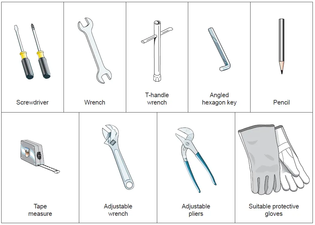
WARNING! THIS APPLIANCE MUST BE INSTALLED BY A QUALIFIED INSTALLER.Improper installation, adjustment, alteration, services, or maintenance can cause injury or property damage. Consult a qualified installer, service agent, or the gas supplier.IMPORTANT: The use of suitable protective clothing/gloves is recommended when handling, installing of this appliance.
TOOLS NEEDED FOR INSTALLATION (NOT SUPPLIED WITH THE APPLIANCE)
GENERAL INFORMATION
- Installation must conform with local codes or, in the absence of local codes, with the National Fuel Gas Code, ANSI Z223.1/NFPA 54 – Latest Edition, CAN/CGA-B149.1 or CAN/CGA-B149.2.
- Installation in manufactured (mobile) home: installation must conform with the Manufactured Home Construction and Safety Standard, Title 24 CFR, Part 3280 [formerly the Federal Standard for Mobile Home Construction and Safety, Title 24, HUD (Part 280)] or, when such standard is not applicable, the Standard for Manufactured Home Installations, ANSI/NCSBCS A225.1, or with local codes where applicable.
- Installation in Recreational Park Trailers: installation must conform with state or other codes or, in the absence of such codes, with the Standard for Recreational Park Trailers, ANSI A119.5.
- WARNING!! This appliance shall not be used for space heating. This information is based on safety considerations.
- All openings in the wall behind the appliance and in the floor under the appliance shall be sealed.
- Keep appliance area clear and free from combustible materials, gasoline, and other flammable vapors.
- Do not obstruct the flow of combustion and ventilation air.
- Disconnect the electrical supply to the appliance before servicing.
- When removing appliance for cleaning and/or service;A. Shut off gas at main supply.B. Disconnect AC power supply.C. Disconnect gas line to the inlet pipe.D. Carefully lift appliance out of cabinet cutout. CAUTION: The appliance is heavy; use care in handling.
- Electrical RequirementElectrical installation should comply with national and local codes.
- Air Supply and VentilationThe installer must refers to local/national codes.
- Gas Manifold PressureNatural gas – 4.0” W.C.P.LP/Propane – 11.0” W.C.P.
WARNING!! ELECTRICAL GROUNDING INSTRUCTIONSThe cooktop must be electrically grounded in accordance with local codes or, in the absence of local codes, with the National Electrical Code, ANSI/NFPA No. 70-latest edition, in Canada Canadian Electrical Code.Installation should be made by a Iicensed electrician.
FOR PERSONAL SAFETY, THIS APPLIANCE MUST BE PROPERLY GROUNDED.If an external electrical source is utilized, the installation must be electrically grounded in accordance with local codes or, in the absence of local codes, with the national Electrical Code, ANSI/NFPA 70.This appliance is equipped with a three-prong grounding plug (NEMA 5-15P) for your protection against shock hazard and should be plugged directly into a properly grounded socket.Do not under any circumstances cut or remove the third (ground) prong from the power plug.
REPLACEMENT PARTSOnly authorized replacement parts may be used in performing service on the appliance. Replacement parts are available from factory authorized parts distributors. Contact the nearest parts distributor in your area.
Installation to the cabinet
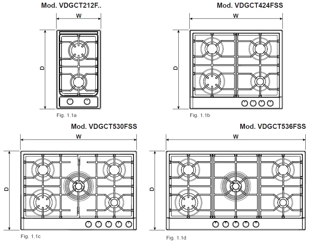
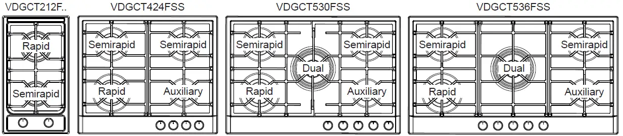
| Table 1 – COOKTOP DIMENSIONS(Figs. 1.1a, 1.1b, 1.1c, 1.1d) | W | D | ||
| MODEL | Inch | mm | Inch | mm |
| VDGCT212F.. | 11” 21/64 | 288 | 20” 1/16 | 510 |
| VDGCT424FSS | 23” 5/8 | 600 | 20” 1/16 | 510 |
| VDGCT530FSS | 29” 17/32 | 750 | 20” 1/16 | 510 |
| VDGCT536FSS | 35” 7/16 | 900 | 20” 1/16 | 510 |
| Table 2 – CUT-OUTDIMENSIONS(Figs. 1.2a, 1.2b, 1.2c, 1.2d) | W1 | D1 | RH
(*) (**) |
LH
(*) (**) |
R
(*) |
T
(***) |
||||||
| MODEL | Inch | mm | Inch | mm | Inch | mm | Inch | mm | Inch | mm | Inch | mm |
| VDGCT212F.. | 10” 5/8 | 270 | 19” 9/32 | 490 | 5” 63/64 | 152 | 5” 63/64 | 152 | 2” 11/64 | 55 | 11” 13/32 | 290 |
| VDGCT424FSS | 22” 3/64 | 560 | 18” 57/64 | 480 | 7” 7/8 | 200 | 11” 13/16 | 300 | 2” 11/64 | 55 | 23” 5/8 | 600 |
| VDGCT530FSS | 29” 9/64 | 735 | 18” 57/64 | 480 | 7” 7/8 | 200 | 11” 13/16 | 300 | 3” 5/32 | 80 | 29” 17/32 | 750 |
| VDGCT536FSS | 33” 5/64 | 840 | 18” 57/64 | 480 | 7” 7/8 | 200 | 11” 13/16 | 300 | 3” 5/32 | 80 | 35” 7/16 | 900 |
- minimum distance from cut-out
- one side (left or right) above the counter height must always be kept clear
- minimum clearance, centred with the cooktop

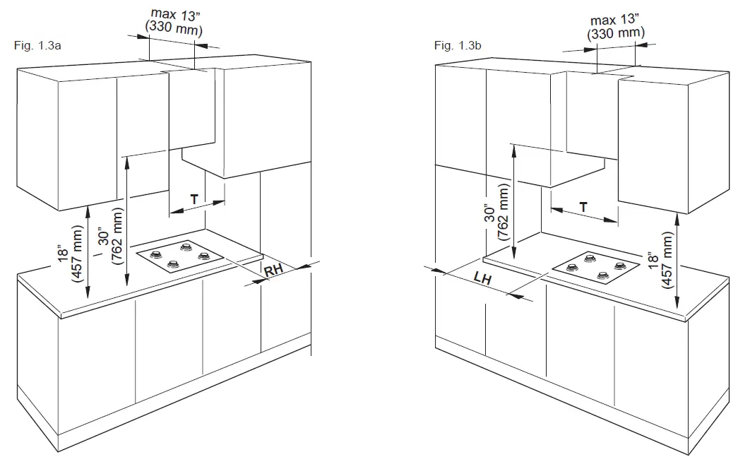
PROXIMITY TO SIDE CABINETS
- The cooktop may be installed directly to existing base cabinets. 24” (610 mm) minimum deep countertop is required.Cooktop dimensions:As per Table 1 at page no.6.Cut-out dimensions:As per Table 2 at page no.6.There must be a minimum clearance between the back side of the cut-out and the back of the countertop as indicated in the Table 2 at page no.6 (measure “R”).Important: Base cabinet construction must allow for size of cooktop cut-out.Gas line opening:Wall – anywhere 8” 1/4 (210 mm) below underside of countertop;Cabinet floor – anywhere within 4” 17/32 (115 mm) of rear wall is recommended.Grounded outlet:The electric cord with 3-prong ground plug has a length of 48” (1220 mm). Grounded outlet should be located within 36” (914.4 mm) of left-centre rear side of cut-out.
- The cooktop CANNOT be installed directly adjacent to sidewalls, tall cabinets, tall appliances, or other side vertical surfaces. There must be a minimum clearance to the right or to the left above the counter height as indicated in the Table 2 at page no.6 (measures “RH” and “LH”). IMPORTANT: ONE SIDE (LEFT OR RIGHT) ABOVE THE COUNTER HEIGHT MUST ALWAYS BE KEPT CLEAR.
- The maximum upper cabinet depth recommended is 13” (330 mm). Wall cabinet above the cooktop must be a minimum of 30” (762 mm) above the countertop for a minimum width as indicated in the Table 2 at page no.6 (measure “T”): it has to be centred with the cooktop. Side wall cabinets above the cooktop must be a minimum of 18” (457 mm) above the countertop.
- If cabinet has a drawer, a 4” (102 mm) depth clearance from the top of the countertop to the top of the drawer (or other obstruction) in base cabinet is required. The drawer depth may need to be shortened to avoid interfering with the regulator.
- Air curtain or other overhead range hoods, which operate by blowing a downward air flow on to a gas cooktop, shall not be used in conjunction with gas cooktops other than when the hood and cooktop have been designed, tested and listed by an independent test laboratory for use in combination.
FASTENING THE COOKTOP
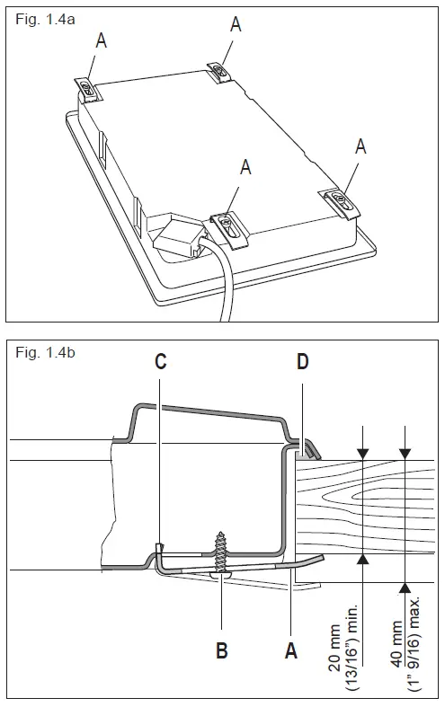
(Model VDGCT212F..)Each cooktop is provided with an installation kit including brackets and screws for fastening the cooktop to benches from 20 to 40 mm (13/16” to 1” 9/16) thick, figs. 1.4a, 1.4b.
• Cut the unit according to Table 2 at page no.6.• Stretch gasket “D” over the edge of the hole made, being careful to overlay the junction edges• Turn the cooktop over and put tabs “A” into the mountings, only tighten screws “B” a few turns. Make sure that the tabs are mounted correctly as shown in the figures. Turn the tabs so that the cooktop can be put into the hole.• Put the cooktop into the hole cut into the unit and position it correctly.• Put tabs “A” into place, tooth “C” of the tabs should go into the hole.• Tighten screws “B” until the cooktop is completely secured.• Using a sharp tool cut off the part of gasket “D” which protrudes from the cooktop. Take care not to damage the benchtop.
(Models VDGCT424FSS, VDGCT530FSS, VDGCT536FSS)
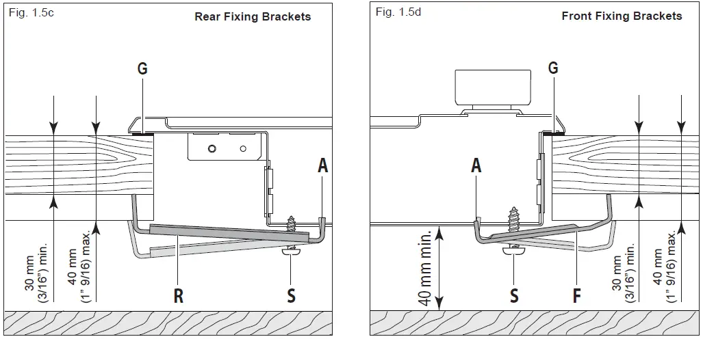
Each cooktop is provided with an installation kit including brackets and screws for fastening the cooktop to benches from 30 to 40 mm (3/16” to 1” 9/16) thick.Models VDGCT424FSS and VDGCT530FSS (fig. 1.5a): The kit includes two “F” type brackets (for the front of the cooktop), two “R” type brackets (for the rear of the cooktop) and four self-threading screws “S”.Model VDGCT536FSS (fig. 1.5b): The kit includes four “F” type brackets (for the front of the cooktop), three “R” type brackets (for the rear of the cooktop) and seven self-threading screws “S”.
• Cut the unit according to Table 2 at page no.6.• Stretch gasket “G” over the edge of the hole made, being careful to overlay the junction edges.• Fasten the brackets “F” and “R” to the appropriate socket holes, without tightening the screws “S” for the moment. Make sure that the tabs are mounted correctly, as shown in the figures. Rotate the tabs so that the cooktop can be put into the cutout.• Put the cooktop into the cutout and position it correctly.• Put the brackets “F” and “R” into place; tooth “A” of the brackets should go into the hole (figs. 1.5c,1.5d).• Tighten screws “S” until the cooktop is completely secured to the bench.• Using a sharp cutter or trimmer knife, trim the excess sealing material around the edge of the cooktop. Take care not to damage the workbench.

Gas Connection
All gas connections must be made according to national and local codes. This gas supply (service) line must be the same size or greater than the inlet line of the appliance. Sealant on all pipe joints must be resistant to the action of LP/Propane gas.The cooktop is equipped for the use with NATURAL gas. It is design-certified by CSA International for NATURAL and L.P. gases with appropriate conversion.The model/serial rating plate, located on the underside of the burner box, has information on the type of gas that can be used. If this information does not agree with the type of gas available, check with the local gas supplier. See page from 14 to 15 for L.P. gas conversion instructions.
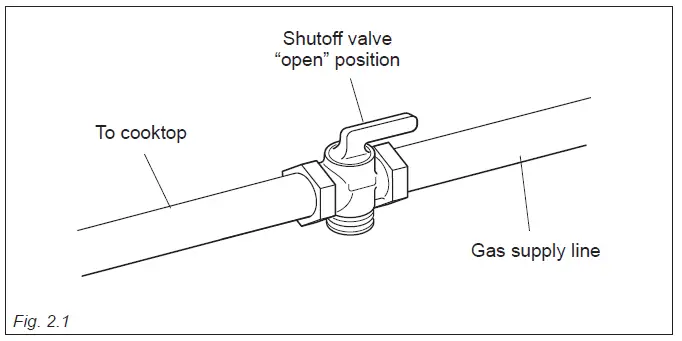
Manual Shut-off Valve (fig: 2.1):A manual shut-off valve must be installed in an accessible location in the gas line external to the appliance for the purpose of turning on or shutting off gas to the appliance (In Massachusetts such shutoff devices should be approved by the Board of State Examiners of Plumbers & Gas Fitters).This valve should be located in the same room as the cooktop and should be in a location that allows ease of opening and closing (in a position where it can be reached quickly in the event of an emergency).Do not block access to the shutoff valve. The valve is for turning on or shutting off gas to the appliance.
WARNING: Explosion Hazard
- Use a new CSA or UL approved gas supply line.
- Install a shut-off valve.
- Securely tighten all gas connections.
- If connected to LP, have a qualified person make sure gas pressure does not exceed 14″ water column.
- Examples of a qualified person include licensed heating personnel, authorized gas company personnel, and authorized service personnel.
- Failure to do so can result in death, explosion, or fire.
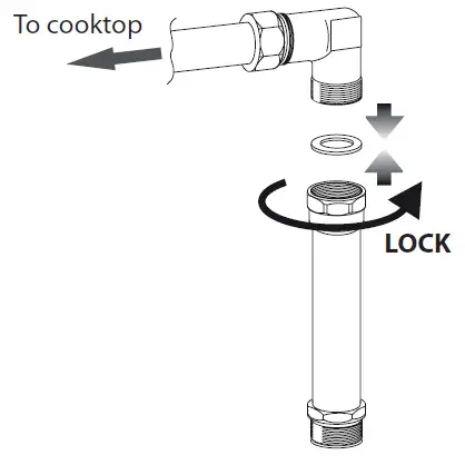
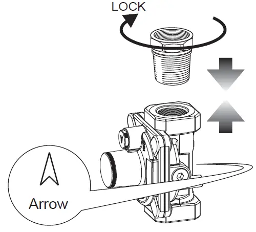
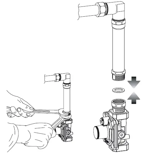
Pressure Regulator:All heavy duty, commercial type cooking equipment must have a pressure regulator on the incoming service line for safe and efficient operation, since service pressure may fluctuate with local demand.Before installing the regulator mount the 3/8” NPT (conical) male connector to the regulator (see picture 2.2c).Gasket supplied has to be placed between 3/8” NPT (conical) connector/extension pipe male pipe fitting (see picture 2.2d).The regulator supplied with this cooktop must be installed before any gas connections are made.Use supplied pressure regulator only.
PRESSURE REGULATOR INSTALLATION

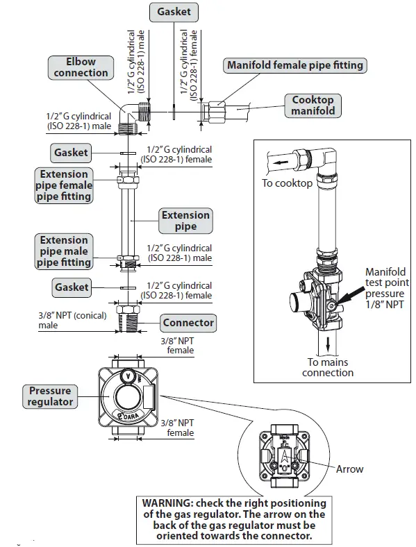
GAS CONNECTION SPECIFICATION
- Any conversion required must be performed by your dealer or a qualified licensed technician or gas service company. Please provide the service person with this manual before work is started on the cooktop. (Gas conversions are the responsibility of the dealer or end user.)
- This cooktop can be used with NATURAL or LP/PROPANE gas. It is shipped from the factory adjusted for use with NATURAL gas.
- Manifold pressure should be checked with a manometer; NATURAL gas requires 4.0” W.C.P. and LP/PROPANE requires 11.0” W.C.P. (see figure below).
- Incoming line pressure upstream from the regulator must be 1” W.C.P. higher than the manifold pressure in order to check the regulator.
- The regulator used on this cooktop can withstand a maximum input pressure of 1/2 PSI (14.0” W.C.P). If the line pressure is in excess of that amount, a step-down regulator will be required.

- The appliance, its individual shut-off valve, and pressure regulator must be disconnected from the gas supply piping system during any pressure testing of that system at pressures in excess of 1/2 PSI (3.5 kPa).
- The appliance must be isolated from the gas supply piping system by closing its individual manual shut-off valve during any pressure testing of the gas supply piping system at test pressure equal to or less than 1/2 PSI (3.5 kPa).

Flexible Connections:If local codes permit, CSA or UL design-certified, flexible metal appliance connector is recommended for connecting this cooktop to the gas supply line. Do Not kink or damage the flexible connector when moving the cooktop. The pressure regulator has 3/8” NPT female pipe threads. You will need to determine the fittings required, depending on the size of your gas supply line, flexible metal connector and shutoff valve.
Rigid Pipe Connections:If rigid pipe is used as a gas supply line, a combination of pipe fittings must be used to obtain an in-line connection to the cooktop. All strains must be removed from the supply and fuel lines so cooktop will be level and in line.
- Use joint compounds and gaskets that are resistant to action of natural or propane gas on all male pipe threads.
- Do not over tighten gas fitting when attaching to pressure regulator. Over tightening may crack regulator.
Leak Testing:IMPORTANT: Leak testing of the appliance shall be conducted as follows:
• After final gas connection is made, turn on manual gas valve and test all connections in gas supply piping and appliance for gas leaks with a soapy water solution. During this test all appliance gas valves have to be closed.• In order to avoid property damage or serious personal injury, never use a Iighted match. If a leak is present, tighten joint or unscrew, apply more joint compound, tighten again and retest connection for leak.
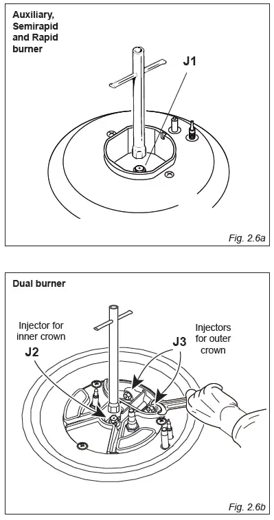
CONVERSION TO LP/PROPANE GAS (OR CONVERSION BACK TO THE ORIGINAL GAS – NATURAL GAS)Every cooktop is provided with a set of injectors for the various types of gas.Select the injectors to be replaced according to the “INJECTORS TABLE”.The nozzle diameters, expressed in hundredths of a millimetre, are marked on the body of each injector.
CAUTION: Save the orifices removed from the appliance for future use.
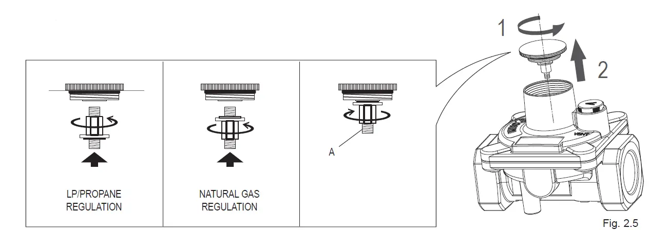
SETTING THE PRESSURE REGULATOR
1. Unscrew the regulator cover.2. Unscrew the “A” component, reverse and screw it according to the LP/PROPANE(or NATURAL GAS) regulation.
INJECTORS TABLE
| NOMINAL POWER | REDUCED POWER | LP/PROPANE
11” W.C.P. |
NATURAL GAS
4” W.C.P. |
|
| BURNERS | BTU/hr | BTU/hr | Ø injector [1/100 mm] | Ø injector [1/100 mm] |
| Auxiliary burner | 4000 | 1000 | 58 | 92 |
| Semirapid burner | 7000 | 1500 | 76 | 123 |
| Rapid burner | 10000 | 2500 | 92 | 148 |
| Dual burner (Mod. VDGCT530FSS) | 16000 (1)
15000 (2) |
5000 | 50 (x1) (3)
73 (x2) (4) |
72 (x1) (3)
135 (x2) (4) |
| Dual burner (Mod. VDGCT536FSS) | 18000 (1)
16500 (2) |
5000 | 50 (x1) (3)
76 (x2) (4) |
72 (x1) (3)
143 (x2) (4) |
- Power calculated with Natural Gas
- Power calculated with LP/Propane
- Inner crown (“J2” in figure 2.6b)
- Outer crown (“J3” in figure 2.6b)
OPERATIONS TO BE PERFORMED WHEN SUBSTITUTING THE INJECTORS
- Remove the pan supports, the burner caps and the flame spreaders.
- Using a wrench substitute the nozzle injectors “J1”, “J2” and “J3” (figs. 2.6a, 2.6b) with those most suitable for the kind of gas for which it is to be used.
- Refit the flame spreaders, the burner caps and the pan supports.
The burners are conceived in such a way so as not to require the regulation of the primary air.
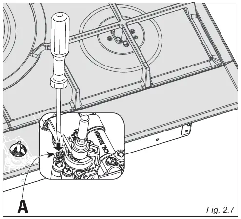
SETTING THE BURNER MINIMUM
When switching from one type of gas to another, the minimum flow rate must also be correct: the flame should not go out even when passing suddenly from maximum to minimum flame.To regulate the flame follow the instructions below:
- Light the burner.
- Set the gas valve to the minimum rate position.
- Remove the knob.
- With a thin screwdriver, turn the regulation screw “A” (fig. 2.7) until adjustment is correct.
For LP/PROPANE gas, tighten the adjustment screw completely.
After regulation repeat the operations indicated in paragraph “2. PRESSURE REGULATOR”.If the cooktop has been disconnected and then connected again to the gas supply line repeat the operations indicated in paragraph “5. LEAK TESTING”.
IMPORTANT:• After conversion to LP/PROPANE gas has been carried out affix near the data plate the conversion label supplied and also affix a conversion label at page 3 of this instruction manual.• After conversion back to the original gas (NATURAL GAS) has been carried out remove, near the data plate and at page 3 of this instruction manual, the LP/PROPANE conversion labels. Save the labels removed for future use.
Electrical Connection
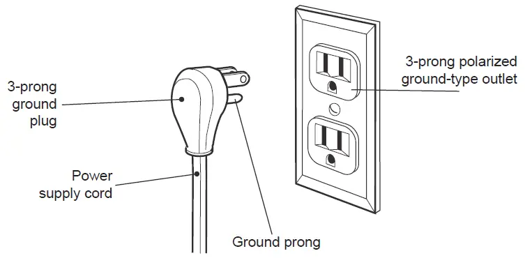
WARNING: Electrical Shock HazardPlug into a grounded 3-prong outlet.Do not remove ground prong. Do not use an adapter.Failure to follow these instructions can result in death, fire, or electrical shock.
If codes permit and a separate ground wire is used, it is recommended that a qualified electrician determine that the ground path is adequate.Check with a qualified electrician if you are not sure whether the cooktop is properly grounded. Do Not ground to a gas pipe.A 120-volt, 60-Hz, AC-only, 15-ampere, fused electrical supply is required.A time-delay fuse or circuit breaker is recommended.It is recommended that a separate circuit serving only this appliance be provided.The outlet must be checked by a qualified electrician to see if it is wired with correct polarity.This appliance, when installed, must be electrically grounded in accordance with local codes.
Recommended ground methodFor your personal safety, this cooktop must be grounded.This cooktop is equipped with a 3-prong ground plug.To minimize possible shock hazard, the cord must be plugged into a mating 3-prong ground-type outlet, grounded in accordance with the National Electrical Code ANSI/NFPA 70 latest edition or Canadian Electrical Code (CSA) and local codes and ordinances. If a mating outlet is not available, it is the personal responsibility and obligation of the customer to have a properly polarized and grounded, 3-prong outlet installed by a qualified electrician.
WARNING VERY IMPORTANT: Before any operation of maintenance disconnect the appliance from the electrical main supply.
ELECTRIC DIAGRAM

 report this ad
The manufacturer cannot be held responsible for possible inaccuracies due to printing or transcription errors in the present booklet.The manufacturer reserves the right to make all modifications to its products deemed necessary for manufacture or commercial reasons at any moment and without prior notice, without jeopardising the essential functional and safety characteristics of the appliances.
References
[xyz-ips snippet=”download-snippet”]