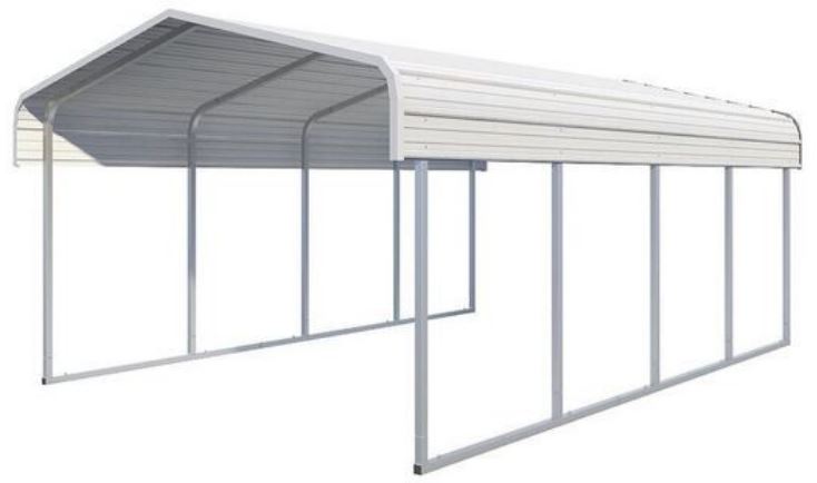
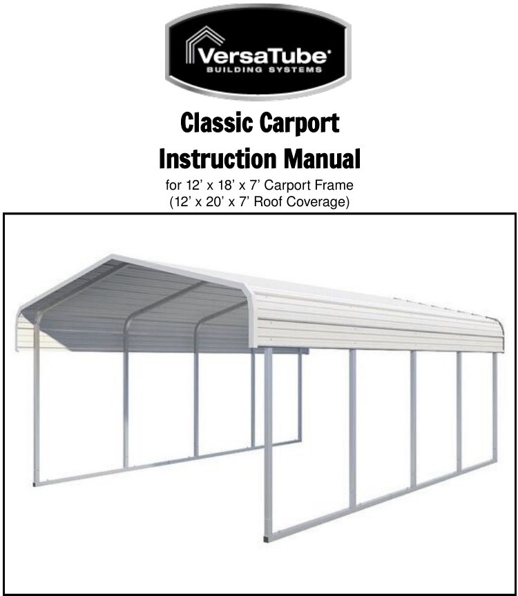
VersaTube Classic Carport
Instruction Manual
Our unique assembly process quickly transforms the individual pieces into a finished structure that will give you a lifetime of service. Great care has been taken to ensure complete satisfaction with your purchase. In the unlikely event that there are any missing or damaged parts, or if you simply need technical assistance, please call our Toll Free Hotline at 1-800-9007222 and your questions will be addressed promptly. Thank you for choosing the VersaTube Building System.
Safety, Hazard, and Maintenance Instructions
![]()
Read the following safety warnings and all instructions in their entirety prior to installation. If you have questions, contact Mid-South Metal Products, Inc. (DBA, VersaTube Building Systems) Customer Service at 1800-900-7222 before proceeding.
![]()
VersaTube Building Systems designs and manufactures framing products to meet minimum load requirements in most areas. It is the buyer’s sole responsibility to determine the specific building code requirements applicable in the city and/or county of the state in which this product is being erected, and to ensure the product is installed with sufficient materials and in such a manner as to comply with the codes.
![]() Metal parts may get hot when exposed to high heat or direct sunlight. Avoid contact with skin and wear protective gloves and clothing to prevent the possibility of burns.
Metal parts may get hot when exposed to high heat or direct sunlight. Avoid contact with skin and wear protective gloves and clothing to prevent the possibility of burns.
![]()
Standing or walking on the structure could cause damage to the sheet metal panels. If you must walk on the roof, step within 1′ of a major frame member. The structure must be properly braced to support human weight. Collapse of the structure may cause serious injury do to weight of components.
![]()
Avoid installation on windy days as wind may create hazards during the installation process. Wind may blow material or cause partially installed components to collapse prior to being secured or fully installed. The weight of the components or structure may cause serious injury if it should collapse.
![]()
Metal conducts electricity and electrical shock hazards exist since the structure is made of metal. During installation or storage, keep the structure and all components away from electrical sources. Make sure that your selected location is away from power lines, underground cables, and any other source of electrical power. Serious injury or even death may occur if contact is made with electrical current.
![]()
In the event that your structure is fully enclosed, be sure to provide proper and adequate ventilation and egress and ingress. Hazardous, poisonous or noxious substances should not be stored in the structures absent proper ventilation. Follow all warnings and instructions of the manufacturer of any substance stored in your building. Also, proper ingress and egress should be provided to prevent persons or children from being trapped inside the structure.
![]()
If metal panels are selected to cover all or a portion of your structure, be careful of the sharp edges which may cause cuts or lacerations. Wear protective work gloves and suitable clothing for protection and always take care when handling metal parts.
![]()
The VersaTube Building System is an all domestically produced galvanized tubular steel framing system. Maintenance is required twice annually on particular areas of the framing system i.e. `’weld seams” and “cut or raw ends”. This maintenance is performed by applying any “Zinc coated” silver spray paint found at local mass merchant or paint store to these areas twice annually or every six (6) months.
![]()
All sheet metal cladding applied to the VersaTube frame are attached with self drilling screws with a rubber washer. These screws produce small shavings when drilling through the cladding. If the shavings are allowed to sit on the sheet metal for an extended period, rust spots will form and promote deterioration. Metal shavings must be brushed after installation of the sheet metal. Claims reported against rust spots will not be honored by Menards.
ATTENTION:
IT IS IMPORTANT THAT YOU READ THE FOLLOWING NOTE BEFORE STARTING THE ASSEMBLY OF YOUR SHELTER
NOTE: If during the installation process you have difficulty fitting frame components together, use an adjustable wrench to open the end of the receiving tube as shown below. Close wrench down around bent portion of tube and bend wall outward. It may also be helpful to hit the center of the swage at the end of the tube to create more of a lead.
![]()
What you’ll need

Items you may need
Hammer Drill, Masonry Drill Bit 1/2″ x 8″, vise grip or other quick clamp (to assist to plumb frame or clamp sheet metal), adjustable wrench and open ended wrench, 3/4″ & 1/2″
Parts List

Site Preparation for Carport
The VersaTube carport is designed to be placed on a foundation that is level side-to-side and sloped about 1″ front- to-back or back-to-front. Concrete Piers are suggested for this structure.
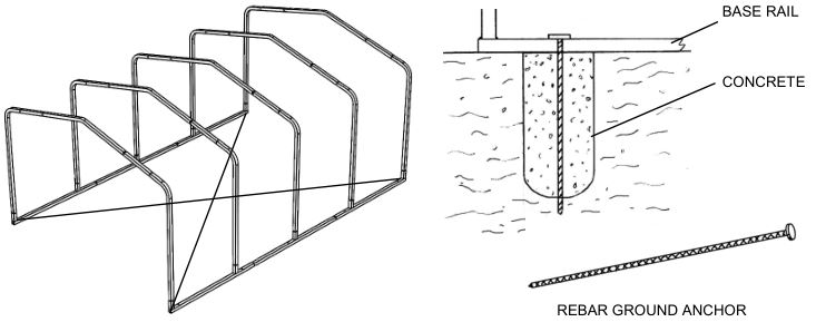
PIERS: Mark the locations of the rails and the anchor holes on the ground. Move the base rails to one side and dig holes at each anchor point for concrete. You may want to rent a gas-powered post hole digger with an 12″ diameter auger for this job. Hole size should be a minimum of 12″ in diameter and 24″ deep. Check with Local Building Officials for frost line depth to ensure the proper anchoring depth for your specific building. If you will be using piers, this is to be done at the same time as laying your base rails out (page 8).

This instruction manual only covers rebar anchor installation into concrete piers. The customer is responsible for any other anchoring/foundation.
Frame Assembly
STEP 1: BASE RAIL ASSEMBLYThere are two runs of base rails. Each run of base rails has a center base rail with one vertical pin and (2) end base rails with two vertical pins. Attach an end base rail to each side of each center base rail. Set the overall length dimension from the end of the end base rails 18′. Fasten the joints on top with two #12 x 3/4″ self-drilling screws. Repeat this assembly for the other run of base rails.

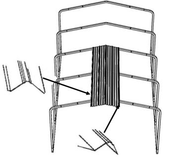
STEP 2: ROOF/WALL FRAME ASSEMBLYOn the ground, assemble two side posts, one peak and two rafters. Measure across the frame assembly at the top, just below the bends and at the bottom. Set the frame width at 12′. Keep the small wrinkles under the peak pointed in the same direction (see below). Try to keep the joints on both sides of the peak equal. With the dimension set at 12′, attach the frame joints with two #12 x 3/4″ self-drilling screws in each joint. Repeat this assembly for the remaining two frames, using the first frame as a template. After all frames are assembled, make a mark on all peak tubes 17 1/8″ up from each end of the peak as shown in the detail below.

STEP 3: ATTACHING THE ROOF/WALL FRAME SECTIONS TO THE BASE RAILS.Place the base rails in the location that you have prepared. Set the front of the base rail assemblies even and 12′ apart outside to outside. Now, set the back dimension 12′ apart. Set one roof/wall frame assembly on the vertical insert pins at the back of the cover. You may want to face the joint assembly screws to the back for a better appearance. Now, install the other four frame assemblies. Attach the side posts to the base rail pins with two #12 x 3/4″ self-drilling screws on the back side of the assembly.

Anchoring
STEP 1: DIGGING HOLES FOR CONCRETEMark the locations of the rails and the anchor holes on the ground. Move the shelter to one side and dig 12″ diameter by 24″ deep holes at each anchor point for concrete (10 total).
STEP 2: ANCHORING CARPORTMove the base rails back into position over the holes. Re-measure to make sure the rails are in the proper location. (12′ apart outside to outside). Measure diagonals to square frame. The diagonal measurements should be equal. Now drop or drive a 30″ rebar ground anchor into each anchor hole. Mix up concrete and pour into holes up to ground level. Before the concrete sets, re-check all your dimensions to make sure the frame is square and has the proper width. Let the concrete cure overnight before installing the sheet metal panels on the roof.
IMPORTANT: You must level and square the frame before you attempt to install sheet metal. Failure to support the frame in a square and level condition will result in crooked sheet metal and possible leaks when frame is shifted for anchoring later.
Installing Roof Sheet Metal
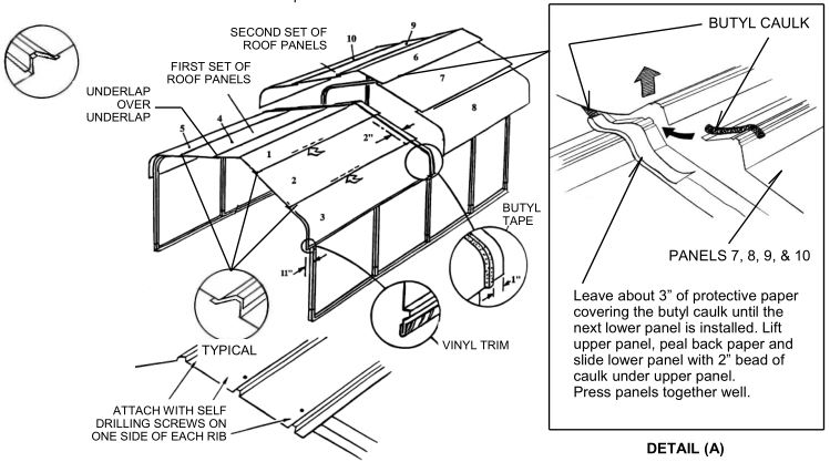
STEP 1: INSTALLING THE FIRST PANEL (10′ PANEL)Each panel has an under lap and an overlap edge. The under lap edge has a small flange at the edge. The overlap edge is just a partial rib with no flange. (See illustration). Place the first panel on the roof in the center of the frame as shown with the flanged of the under lap edge of the panel lined up with the marks that you put on the peak tubes. This will center the first panel on the frame. The ends of the panel should overhang the ends of the frame 11″. Fasten the panel to the frame with #12 x 1″ painted, self-drilling screws with sealing washers. Place screws in the pattern indicated in the in the illustration below. Do not install screws next the center rib of the panel. Also, do not install screws above the lower edge ribs of the panel at this time. You will be sliding the lower panels under the first panel.
STEP 2: INSTALLING ROOF PANELS (2 THROUGH 5) 10′ PANELSPanels 2 through 5 are the remaining front panels. Place the upper edge or (under lap rib) of panel 2 under the edge of panel 1, flush the front edge and fasten with self-drilling screws (N) as described earlier. As with the first panel, do not place screws above the lower rib or in the center Roof/Wall frame section. Note that on one side of the roof you will be inserting an under lap rib under an under lap rib. This is ok. All other joints will be under lap ribs under overlap ribs. (Install panels in number sequence.) Do not install screws above the bottom rib until you have installed the vinyl trim.
STEP 3: INSTALLING BUTYL CAULK TAPEAdhere Butyl Caulk on the top of panels 1 through 5 at the center of the structure 1″ from the back edge. This will seal panels 6 through 10 to panels 1 through 5. Start at the bottom of panel 3 and run Butyl Caulk up and over the Peak and down to the bottom of panel 5. Clip the protective paper backing at the peak of the roof and peel back the paper to within 3″ of the lower edge of the panel as you go. You will want to be able to lift the lower edge of each panel to install the next lower panel.
STEP 4: INSTALLING ROOF PANELS (6 THROUGH 10) 10′ PANELSWhen you have clipped the protective paper on the butyl caulk at the peak and pealed it back on both sides of the roof to within 3″ of the next lower panel, position the end of panel (6) with a 2″ overlap onto panel (1). Press the panels firmly together to squeeze the caulk and seal the joint. Take care to get panel (6) lined up square on the roof like you did panel (1). This will keep all of the lower panels straight. As you install panels 7 through 10 place a 2″ bead of butyl caulk on the end of the top underlap rib to seal the panel corner. See detail (A) above. Install remaining panels in number sequence following the same instructions as panels 1 through 5. (Install screws in the overlap at the center of the building at this time.) Do not install the screws above the bottom rib on panels 8 and 10 until you install vinyl trim on the edges. Reminders: Keep Roof/Wall frame assemblies plumb. Keep 11″ overhang straight over the frame.
STEP 5: INSTALLING VINYL TRIMInstall Vinyl Trim on the bottom of the roof sides on each side of the building. If you installed the screws above the bottom side edges, you may want to loosen the screws in order to install vinyl trim. Push the trim securely over the sheet metal edge by hand. A small hammer may help fit trim over major ribs. When all of the trim has been installed, install the screws above all bottom bibs on the sides of the carport.
Installing Gable Angle Trim
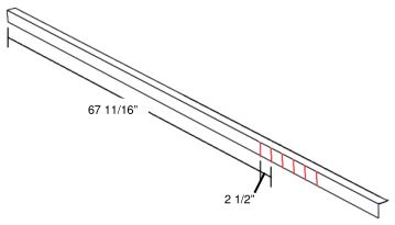
STEP 1: MARKING AND CUTTING TRIMTo trim out the gable ends, (4) pieces of 1-1/2″x2″x93″ Angle Trim has been provided. It is important to note that the 2″ face will be facing down and the 1-1/2″ face will be laid on top of the roof sheet metal. First make a mark on the 2″ face at 67 11/16″ from the end that will be at the peak. From that mark, make five more marks every 2-1/2″. These will be your dovetail cut marks. Cut from the bottom of the 2″ face up to the angle bend at all 6 locations.
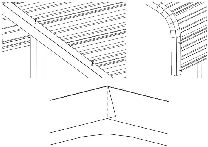
STEP 2: INSTALLING TRIMPlace the trim on your rafter line with the cut end down toward the eave corner. Push the upper end of the trim to the center of the peak. Once placed, attach the trim to the sheet metal by driving a painted sheet metal screw through the trim into every other major rib. Continue this until you are ready to bend the cuts around the eave corner. Make the dovetails bend as evenly as possible. After the bend, attach the trim to the next major rib on the vertical face. Repeat for each rafter line. If desired, one piece gable trim per end can be cut at the peak to create a vertical trim line.
[xyz-ips snippet=”download-snippet”]