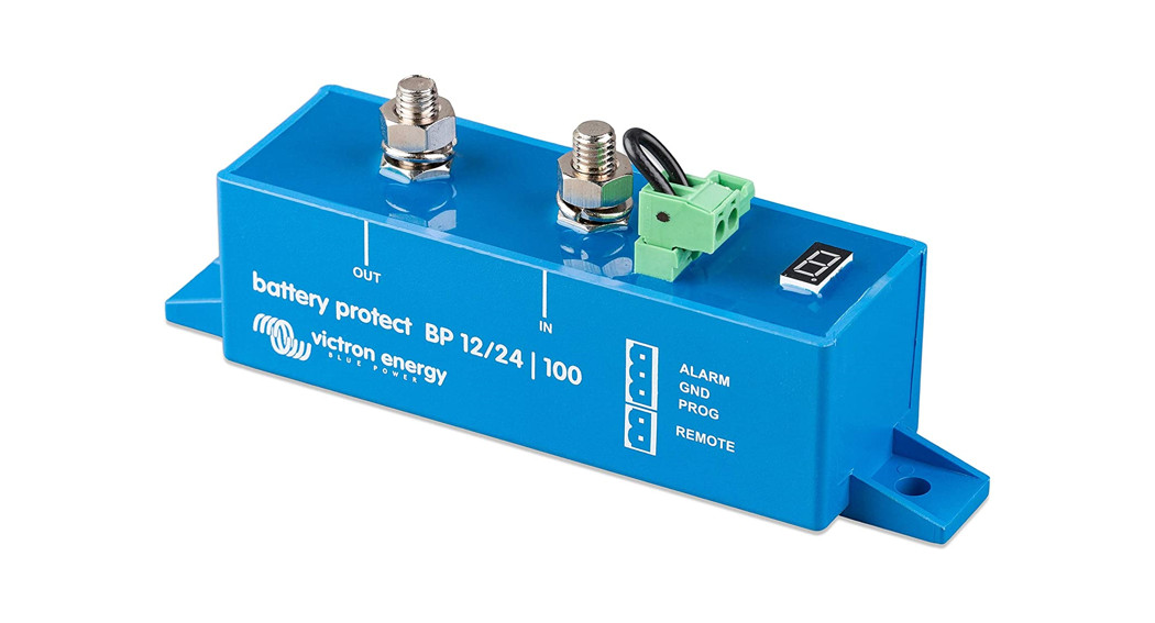
 BatteryProtect 12/24 V
Installation
![]()
- The BatteryProtect (BP) must be installed in a well-ventilated area and preferably close (max 50 cm) to the battery (but, due to possible corrosive gasses not above the battery!). Voltage drops over a long or undersized cable between the battery plus and the BP may result in a short circuit alarm when starting up the load, or unexpected shutdown.
- A properly sized fuse must be inserted according to local regulations in the cable between the battery and the BP.
- The BP is designed to allow current to flow from IN (battery) to OUT (load) terminals only.Reverse currents from OUT to IN terminals are strictly forbidden and will damage the device. If you wish to use the BP as a disconnection for a charge source, you must orient the unit in the system so that the current is flowing in the intended direction, IN to OUT.
- The short circuit protection of the BP will be activated if you try to directly connect loads with capacitors on their input (eg inverters). Forthat use case, please use the BP to control the remote on/off switch on the inverter, instead of disconnecting the higher power DC line.
- Use a 1,5mm2 wire (included) for the minus connection, which should be connected directly to the battery minus. No other equipment should be connected to this wire.
- The BP automatically detects the system voltage one time only after connection of plus and minus to the selected voltage (12 or 24 V) is stored, and further automatic detection is disabled. See d in the programming table for how to reset it when re-using the BP in a different installation.
- Do not connect the load output until the BP has been fully programmed.
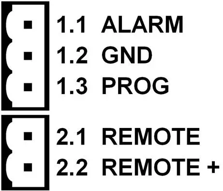
- A remote on-off switch can be connected to the two-pole connector (see figure 1) or between pin 2-1 of the two-pole connector and the battery plus.
- A buzzer, LED or relay can be connected between the alarm output and the battery plus (see figure 1). Maximum load on the alarm output: 50 mA (short circuit proof).
Load disconnect events and alarm output options
Buzzer or LED mode (buzzer or LED connected to the alarm output):
- In case of under-voltage, a continuous alarm will start after 12 seconds. The BP will disconnect the load after 90 seconds and the alarm will stop. Reconnect delay: 30 seconds.
- In case of overvoltage, the load will be disconnected immediately and an intermittent alarm will remain on until the overvoltage problem has been corrected. There is no reconnect delay.
Relay mode (relay connected to the alarm output):
- In case of under voltage, the relay will engage after 12 seconds. The BP will disconnect the load after 90 seconds and the relay will disengage.
- In case of overvoltage, the load will be disconnected immediately and the alarm output will remain inactive. Overvoltage trip levels: 16 V respectively 32 V
Li-ion mode:
- Connect the load disconnect output of the VE. Bus BMS to pin 2-1.The load is disconnected immediately when the load disconnect output of the VE. Bus BMS switches from ‘high’ to ‘free floating’ (due to battery cell under-voltage, over-voltage, or over temperature).The under-voltage thresholds and alarm output of the BP are inactive in this mode.
Operation
There are 4 possible error modes, indicated by the 7-segment display:
E 1Short circuit detectedE 2Overload or over temperatureE 3Under voltageE 4Overvoltage
After 5 minutes the error is no longer displayed to reduce current consumption.The decimal point of the 7-segment display is used for status indication:
- On solid: the BP attempts to activate the output
- Flash every 5s: output is active
- Flashing every 2s in Li-ion mode: output ‘connecting’
Remote control and short circuit
- The BP will connect the load 1 second after closing the remote contact.
- The BP will disconnect the load immediately when the remote contact is opened.
- When in Li-ion mode the BP will connect the load 30 seconds after the remote input of the BP has been pulled high by the VE. Bus BMS. This delay increases to 3 minutes in case of frequent switching.
- In the case of a short circuit, the BP will attempt to connect the load every 5 seconds. After two attempts the display will show
E 1(short circuit detected).
Programming
When switched off (remote open), the BP can be programmed for the desired voltages and modes by connecting the PROG pin to the ground. Please see the programming table.The display will first step through the shutdown and restart voltages. Disconnect the PROG pin when the desired voltage is displayed.The display will confirm the chosen voltage and default mode (A) twice.Reconnect the PROG pin to the ground if another mode is (b, c or d is required. Disconnect when the required mode is displayed.The display will confirm the chosen voltage and mode twice.Programming table
|
7 segment display |
Under voltage shut down12 V / 24 V system |
Under voltage restart12 V / 24 V system |
0 |
1015 V/ 21 V | 12V/24V |
1 |
10V/20 V | 1115 V/ 23 V |
2 |
9,5 V / 19 V | 1115 V/ 23 V |
3 |
11,25 V/ 22,5 V | 13,25 V/ 26,5 V |
4 |
11,5V/23V | 13,8 V / 27,6 V |
5 |
10,5 V/ 21 V | 12,8 V / 25,6 V |
6 |
11,5V/23V | 12,8 V / 25,6 V |
7 |
11,8 V / 23,6 V | 12,8 V / 25,6 V |
8 |
12V/24V | 13V/26 V |
9 |
10V/ 20 V | 13,2 V / 26,4 V |
A |
Buzzer or LED mode | |
b |
Relay mode | |
C |
Li-ion mode | |
d |
Detect system voltage |
Specifications
| BatteryProtect | BP-65 | BP-100 | BP-220 |
| Maximum cont. load current | 65 A | 100 A | 220 A |
| Peak current | 250 A | 600 A | 600 A |
| Operating voltage range | 6 –35 V | ||
| Current consumption | When on: 1,5 mA When off or low voltage shutdown: 0,6 mA | ||
| Alarm output delay | 12 seconds | ||
| Max. load on alarm output | 50 mA (short circuit proof) | ||
| Load disconnect delay | 90 seconds (immediate if triggered by the VE.Bus BMS) | ||
| Load reconnect delay | 30 seconds | ||
| Default thresholds | Disengage: 10,5 V or 21 V Engage: 12 V or 24 V | ||
| Operating temperature range | Full load: -40 °C to +40 °C (up to 60 % of nominal load at 50 °C) | ||
| Connection | M6 | M8 | M8 |
| Mounting Torque | 5 Nm | 9 Nm | 9 Nm |
| Weight | 0,2 kg 0.5 lbs | 0,5 kg 0.6 lbs | 0,8 kg 1.8 lbs |
| Dimensions (hxwxd) | 40 x 48 x 106 mm1.6 x 1.9 x 4.2 inch | 59 x 42 x 115 mm2.4 x 1.7 x 4.6 inch | 62 x 123 x 120 mm2.5 x 4.9 x 4.8 inch |
Example Wiring Diagrams
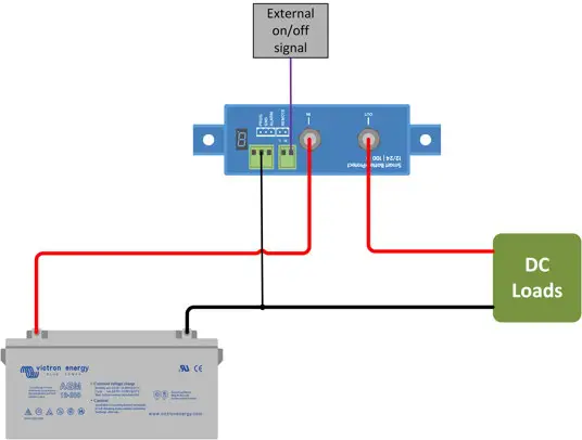
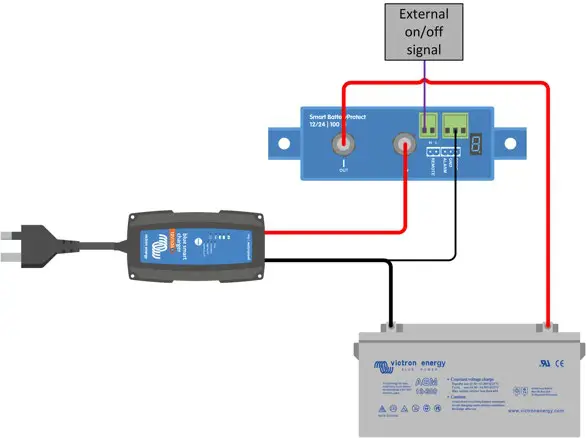
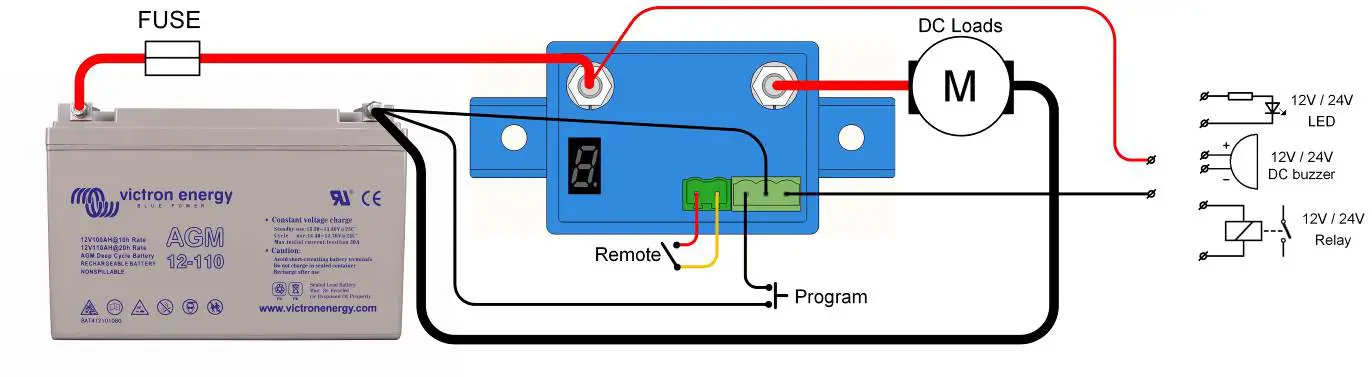 Figure 1: Connection diagram of the BP-65
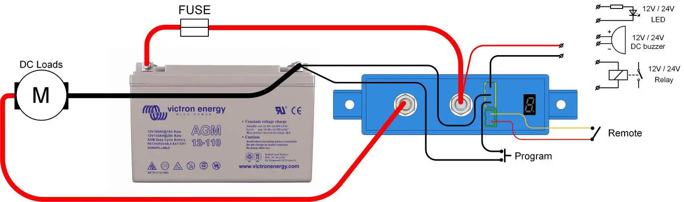
Figure 2: Connection diagram of the BP-100 and BP-220
 |
| (remote switch can also be connected between pin 2.1 and battery plus) |
| (protected against short circuit with internal 10kΩ series resistor) |
Figure 3: Connectors and pin numbering

Figure 4: System with Li-ion battery
Note: The BP will disengage when its control input becomes free-floating. If the battery voltage recovers after disconnecting (which will happen when no other loads are connected to the battery), the output of the Ve. Bus BMS will become high and the BP will re-engage after 30 seconds.After 3 attempts to re-engage, the BP will remain disengaged until the battery voltage has increased to more than 13V (resp. 26V) for at least 30 seconds (which is a sign that the battery is being recharged). The under-voltage thresholds and alarm output of the BP are inactive in this mode.
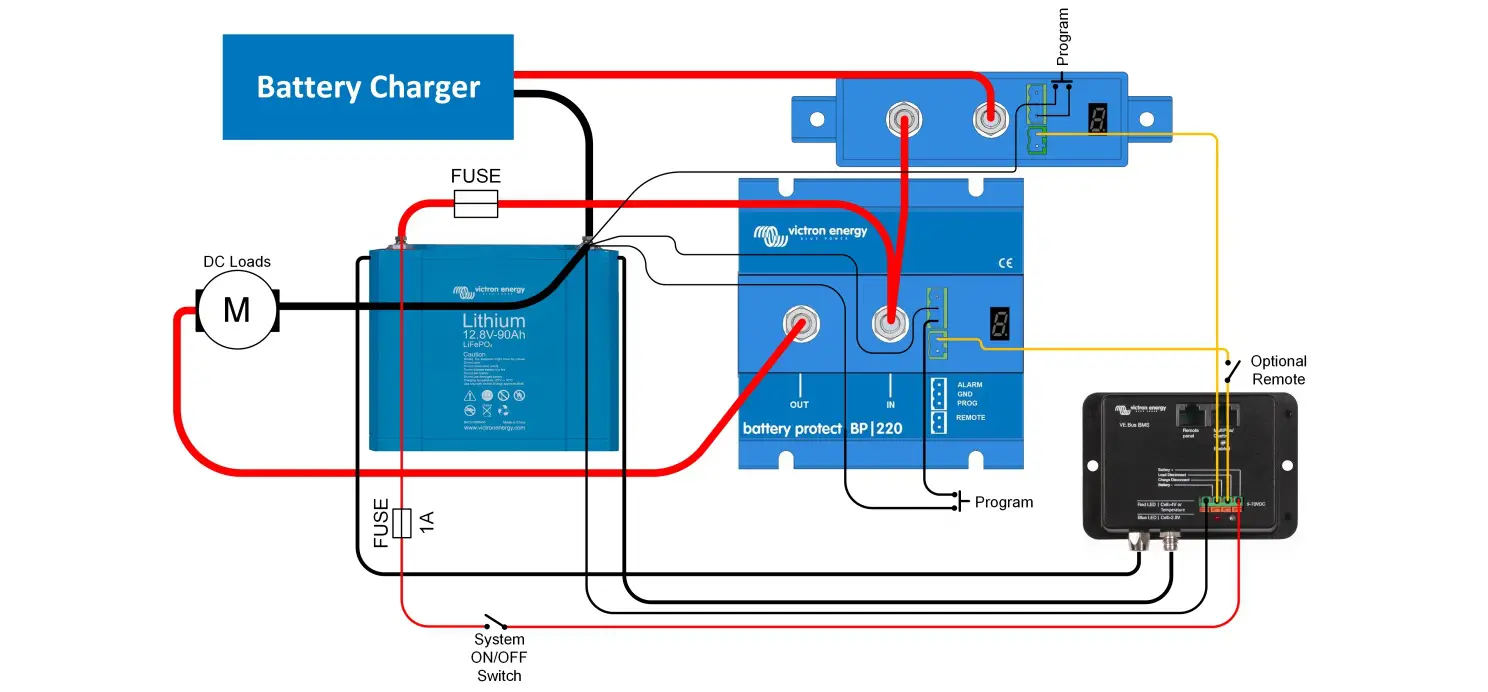
Figure 5: Second Battery Protect in between a battery charger or MPPT solar charge controller and a Li-ion batteryThe second BP replaces a Cyrix-Li-charge relay (advantages: lower power consumption, alarm relay).(not applicable if the charger has remote on-off contacts and can be controlled with an interface cable between the BMS and the charger)Choose a program C for this application.Caution: uncontrolled reverse current will flow through a Battery Protect if Vout > Vin. Therefore never use a Battery Protect for the battery to battery charging.
APPENDIX
Error CodesE1: Short circuitShort circuit protection is activated in the event of a short circuit, an overload condition, or excessive inrush current – such as when attempting to directly power an inverter

- Check for a potential short circuit condition
- Confirm that the load current draw does not exceed the BP current rating
- Use the BP to control the remote on/off switch on loads with high inrush currents, rather than directly powering/disconnecting the DC supply
- Check for loose/high resistance connections and ensure that appropriate gauge wiring is used in the installation
E2: Over temperatureOver-temperature protection is activated in the event of excessive internal temperature
- Confirm that the load current draw does not exceed the BP current rating
- Check for loose/high resistance connections and ensure that appropriate gauge wiring is used in the installation
- Do not install the BP unit in a location exposed to high temperature or radiant heat – relocate BP to a cooler position or provide additional active cooling
E3: Under voltageUnder-voltage protection is activated in the event that the input voltage drops below the under-voltage limit selected for 90 seconds
 report this ad
- switch off/disconnect loads and recharge the battery
- Check charging system and battery for proper operation
E4: Over voltageOver voltage protection is activated in the event that the input voltage exceeds 16V (for 12V systems) or 32V (for 24V systems)
- Confirm the configuration of all charging devices in the system – particularly system voltage and charge voltage settings
- Check charging system for proper operation
- Confirm BP system voltage configuration is correct
Victron Energy B.V. / De Paal 35 / 1351 JG ALMERE / NederlandTelefoon: (+31) (0)36 535 97 00www.victronenergy.com E-mail: [email protected]Rev16 28-04-2021
References
[xyz-ips snippet=”download-snippet”]