TNT Tramp HV 5.8 GHz Video Transmitter Operator’s Manual

Specifications
RF Output |
|
| Antenna Impedance | 50 Ohms |
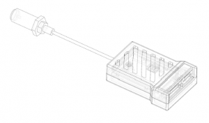
| Antenna Connector | Surface Mounted U.FL, with replaceable U.FL to SMA pigtail |
| Power Output | Linearly adjustable, < 1mW to > 600mW 2 |
| Channels | 40 standard, arbitrary using Race Wand |
| Pit Frequency | User/Race Organizer Definable |
| Channel Change Glitching | Eliminated using Auto-Glitch technology |
Mechanical |
|
| Dimensions | L=32mm x W = 14mm x H = 5mm |
| Weight | 4g (Tx only without SMA pigtail) |
Audio/Video |
|
| Connector | L=32mm x W = 14mm x H = 5mm |
| Weight | 4g (Tx only without SMA pigtail) |
Audio/Video |
|
| Connector | JST-GH, 6-pin locking |
| Pinout | Battery In, Gnd, +5V Out, Video, Audio, Telemetry (twin grounds on harness) |
| Modulation | FM, Audio and Video |
| Audio | Mono input, duplicated on subcarriers on 6.0 and 6.5MHz 1 |
TNR (Touch’n’Race) |
|
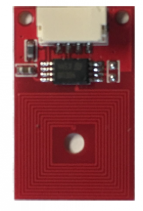
| Connector | JST-GH, 4-pin locking |
Power |
|
| Voltage | 2s-4s HV LiPo |
| Power Consumption | ~4W max. @ 600mW, ~1.9W @ 200mW |
Environmental |
|
| Storage Temperature | TBD |
| Operating Temperature | TBD |
- Mono audio duplicated on both audio subcarriers to eliminate noise in one channel of stereo headphones at the (stereo) receiver.
- Power limited by Tx temperature to extend transmitter lifetime. A hot transmitter (no airflow) will reduce power until safe temperature is reached.
Introduction
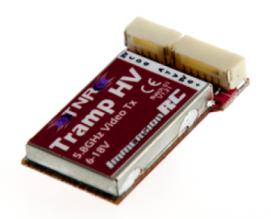
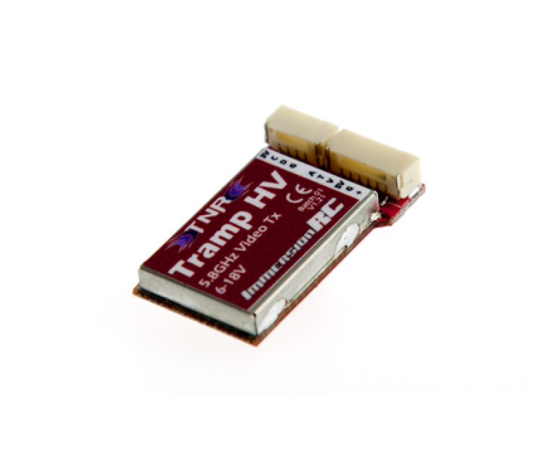
The Tramp HV is a tiny, high power 5.8GHz Audio/Video transmitter designed for FPV use, but with a focus on the Drone Racing market.Equipped with a dual user-interface, one a traditional button/LED, and another using near-field communications (Touch’N’Race) to configure the transmitter using a contact-free wand.The unique (and Patent-Pending) Touch’N’Race (TNR) feature was designed purely to enable race events with extremely low inter-heat times, and reduce dramatically the risk of accidentalpower-ups disrupting a race event.
Touch’N’Race (TNR)
When arriving at a race event using ImmersionRC TNR Technology, a pilot’s quad is placed in ‘Race Mode’ during pilot registration. This is achieved without powering up the quad, and without anyphysical connection, using a TNR Wand. When in Race Mode (identified by a blink code on the internal LED), the transmitter will not transmit unless requested by the race director’s TNR Wand. This typically happens during preparation for a race, while the previous heat is running.Quads are ‘wanded’ safely while their batteries are disconnected, and assigned their race band, channel, and transmitter power level. When powered up, the quads will transmit on this assignedchannel until the battery is disconnected, at which point they will return to the race-director assigned mode. A race organizer may choose to allow quads which are not racing to transmit a very low power level on a ‘Pit Frequency’ to allow quads to be setup, and debugged, without interrupting a race. This pit frequency is defined by the race organizer to comply with local regulations. This Pit Mode also allows quads powered up for equipment inspection to transmit an image.
Note that when leaving a race event, be sure to ‘De-Wand’ to place the transmitter back in normal operating mode. If you leave an event without De-Wanding, check the ‘EmergencyUnlock’ procedure later in this document.
Best Practices
Connectors and CablesThe trend to miniaturize FPV video transmitters, and dramatically decrease weight requires the use of smaller, and therefore more fragile connectors than used on ‘legacy’ transmitters.When mounting the transmitter, ensure that these connectors (especially the tiny U.FL antenna connector) is not being pulled, or can be pulled in a crash. If the U.FL to Bulkhead SMA cable getsdamaged it may be replaced easily. The transmitter may safely be stuck to the inside of a carbon fibre frame using double-sided foam tape. Try to avoid sharp bends in the tiny RF cable, which will reduce power output levels.
Powering the Tramp
DO NOT power the tramp from a 12V regulator on a 4s powered quad, such as a Polulu. The Tramp is designed to run directly from the LiPo , and includes an advanced switchingregulator, and plenty of filtration to clean up the noise from the ESCs. Powering from a +5V supply is possible, but only recommended if the regulated supply is very clean’, and can supply up to 1 Amp of current.
Airflow
Even though the Tramp is equipped with a thermal protection system, it is recommended to ensure a good amount of airflow around it. Encasing the Tramp (or any other high-power electronic device)in foam (or similar) with no airflow is not recommended, and may result in premature failure.The Tramp HV will intelligently reduce output power levels if the board temperature heats beyond preset limits.Several steps are used, starting with the least aggressive (25% reduction in output power), until the board temperature is safe, and sustainable.
Ground Loops
If using the internal +5V regulator to power a camera, run the second ground wire from the supplied harness, along with the +5V output, directly to the camera. This ensures that the cleanswitching regulator on the Tramp can feed the camera without noisy ‘ground currents’ creating noise on the image.
TNR Board
The TNR board must be placed on your quad so that it is accessible by the race marshal. If you have a flat carbon fibre top plate (which is the case for 99% of the quads out there), you may stick it tothat plate with some double-sided tape. Use the thicker ~1mm thick foam tape instead of the very thin ‘carpet tape’ to ensure that the close proximity of the frame doesn’t affect the TNR range.

NOTE: For the tramp version used for events in July/Aug 2016, please connect the TNR board to the Tramp and power it up at least once before arriving at race events. The first customer release will notrequire this.
Antenna Compatibility
The pigtail supplied with the Tramp sports a standard SMA connector, NOT a RP-SMA which is used by some other manufacturers. If a RP-SMA connector is screwed onto a standard SMA, it will appear to be connected, but will actually be open-circuit, potentially damaging the Tx. Ensure that one of the connectors has a pin, and the other has a hole to receive the pin. If bothhave a hole (or both have a pin) then they are not compatible.
User Interface
Button/LEDStartup LED BehaviorThe LED indicates the state of the transmitter shortly after powerup. Steady On means that the transmitter is currently transmitting in ‘Normal Mode’, and will behavemuch like any other FPV Transmitter. A short blink sequence (. . . ) means that the transmitter is in Race Mode, and is either not transmitting, or transmitting low-power on a pre-configured Pit Frequency.A long blink sequence (- – -) means that the transmitter is in Race Mode, and is currently transmitting on its assigned Race Frequency.
First, a disclaimer, this transmitter was not designed to use the button as the primary user-interface. The TNR Wand is by far the easiest way to configure the transmitter, and provides both feedback of which channel a transmitter is on before it is powered up, and define the current band/channel, and power level. Three ‘Menu Options’ are available using the button and LED, shown in the flowchart below
NOTE: When in Race Mode, under the control of the race director, the button will have no effect, other than the unlock procedure below.
Emergency Unlock procedure (leaving Race Mode after an event) If the Tramp was not removed from Race Mode after an event, a simple procedure may be followedto manually unlock it. Press the button on the side of the tramp before applying power, apply power, and hold the button for 30 seconds until the LED is lit. (Yes, we know this is tedious, but it is this way to reduce the probability of accidentally leaving race mode at an event)

NOTE: Transmitters distributed for events in Summer 2016 will be limited to 350mW max. Power while the thermal protection system is finalized. First customer shipments will emit 600mW ormore.
Bands, Channels, and Frequencies
Depending upon the Tramp variant purchased, the power output level, and available transmit frequencies can vary.It is highly recommended to understand the rules and regulations in your country before using the Tramp. Transmitting outside a legal band is something frowned upon by the authorities, and mayresult in a fine, or confiscation of equipment. As a rule of thumb, the following charts should help understand which frequencies are legal in each of our main markets.
International Version
ITU Region 2: The Americas
ITU Region 1: Europe
Thermal Regulation
This is an area where the Tramp differs from most 5.8GHz video transmitters on the market. Transmitters of this size and weight class, which shed the traditional heat-sinks used to keepelectronics cool, need to protect themselves against overheating by being a little smarter. The Tramp HV continuously monitors the internal temperature, and regulates the power output inseveral steps until the temperature is within safe limits. This practice ensures that the components used in the transmitter are not used outside of their maximum operating conditions, and will eliminate premature failures. When in a reduced power output mode, as soon as airflow is present, the transmitter will quickly increase power output to requested levels. When is this useful? Imagine a quad sat on the starting grid of a race for several minutes, as other pilots get ready, props stationary. The Tramp HV will lower its power output until a safe level is reached. As soon as the quad takesoff, the airflow from the props will quickly cool the transmitter, and increase power output before the quad reaches a distance from the pilot where full power is required.
Note that as with any high-power video transmitter, ensure that adequate airflow is available when a model (whether it be a wing, or a quad) is in normal flight.
TroubleshootingOn startup, 2x blinksTNR Device detected, but data appears corrupted.On startup, 3x blinksNo TNR Device connected/detected (informational code, Tramp will run happily without this connected)On startup, 10x blinksTNR Device detected, but cannot write to it.LED does not light at power-upThis is almost definitely due to a supply voltage problem, check all cabling to the Tramp.

Revision History
V1.21– Initial revision used at the Swiss, and NYC NationalsV1.22
– Change in behavior when detecting an uninitialized TNR board at boot. Race mode request using the wand will always be respected on first power-up at an event.– Change in button behaviour, a device in Race Mode, wanded and ready to fly, will ignore the button, even for emergency unlock requests. This only affects cases where the Tramp was installed with the button pressed before powerup, and for 30s after powerup.– Thermal protection behaviour modified to handle extreme lack of airflow, and high power levels, cases not normally seen in general use.– 600mW power level added in the Button/LED UI.
Read More About This Manual & Download PDF:
TNT Tramp HV 5.8 GHz Video Transmitter Operator’s Manual – TNT Tramp HV 5.8 GHz Video Transmitter Operator’s Manual –
[xyz-ips snippet=”download-snippet”]


