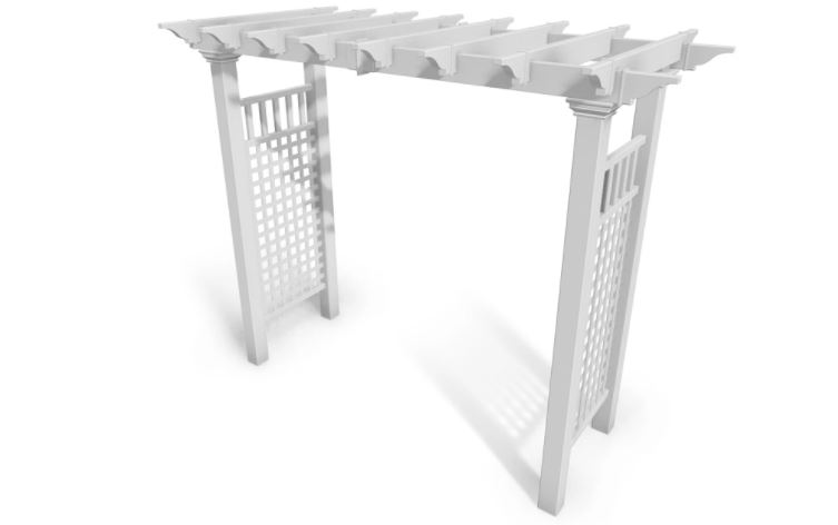
vita Fairfield Grande Arbor
Instruction Manual

Check Box for These Contents
In the event of missing or defective parts please call our customer service dept. at 1 800 282 9346 (Mon. to Fri. 8:00 AM to 5:00 PM EST).
1. Rafters (8) Length 38″ (96.5 cm) – 108382. Pergola End Caps (20) – 10700-13. Post Caps (4) – 108244. Right Posts (2) Length 84″ (213 cm) – 107925. Left Posts (2) Length 84″ (213 cm) – 108216. Post T rims (4) – 10737-17. Carrying Beams (4) Length 46 1/2″ – 108398. Side Panel T op-Rails (2) Length 31 5/8“ (80 cm) – 108229. Side Panel Vertical Spindles Length 10 3/8” – 1079510. Side Panel Middle Rails (2) Length 31 5/8“ (80 cm) – 1082311. Side Panel Square Lattices (2) Length 47 3/4” – 1079312. Aluminum Stiffener Inserts (2) – 1099613. Carrying Beam Coupler (2) – 10707-114. Side Panel Horizontal Bottom Rails (2) Length 31 5/8″ (80 cm) – 1079415. 3 in. (76 m.) Stainless Steel Screws (32) – 2000716. 1 1/2 in. (38 mm.) Stainless Steel Screws (12) – 2000517. Tube of Vinyl Glue (2) – 20000
Tools You Will Need
• Hammer• Tape Measure• Level• Stool or Short Ladder• Shovel or Auger• Cordless Drill• 1/8” x 2” Steel Drill Bit
General Information
• Read Instructions through carefully before beginning assembly.• When assembling components, place on a non-abrasive surface (i.e. shipping box) to avoid scratching.• We recommend an area approx 10’x 8 ‘ (3 m x 2.4 m) for unobstructed assembling.• You should not need to use excessive force when assembling components.
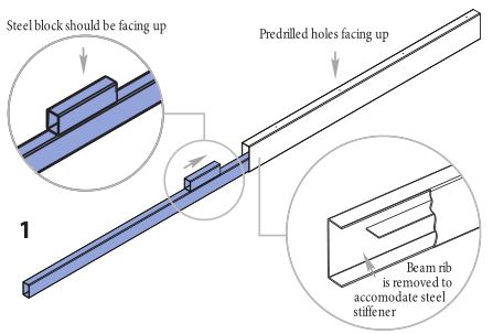
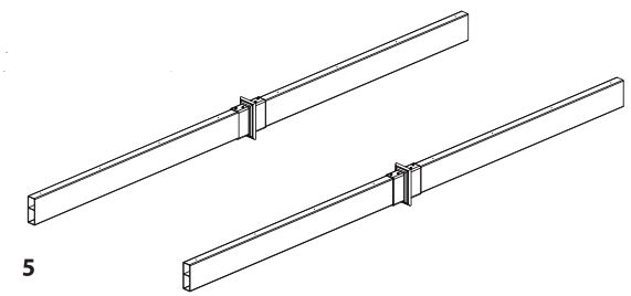
STEP ONEAssemble the Arbor Beams
- Insert one steel stiffener (with steel block facing up) into the lower pocket of the beam past the joiner. Push until steel block hits the internal ribbing.

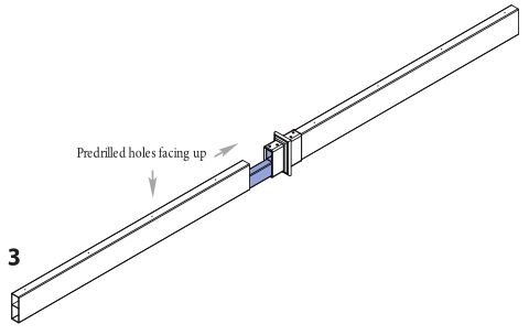
- Slide the beam coupler over the beam. Install the coupler so that the four holes are facing up. Push firmly until the coupler bottoms out on the beam.
- Slide a second beam coupler over the steel insert and into the coupler.
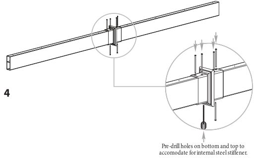
- Screw the coupler to the vinyl beams and steel using 1 1/2” (38 mm) screws. The bottom and top holes will need to be predrilled using the steel drill bit (not provided)
- Repeat for second beam.

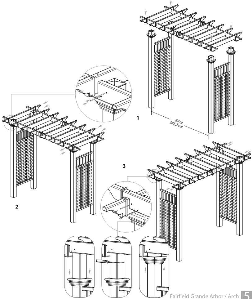
STEP TWOAssemble the Arbor Top
- Lay out the two carrying beams as illustrated with pre- drilled holes facing up.
- Position the eight rafters over the respective pre drilled holes on the carrying beams as illustrated. Using the 3” (78 mm) screws, fasten the eight rafters to the carrying beams.Note: The self-augering screws will drill through the internal rib. Keep the screw straight to drill through the internal rib.
- Apply a thin bead of vinyl glue to the inside of the end capand install pergola end caps as illustrated.

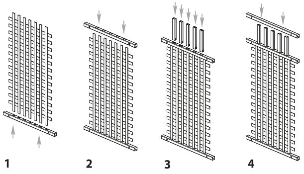
STEP THREEAssemble the Side Panels
- Insert the lattice into the bottom rail as shown.Note: Bottom rail will have 7 holes on one side only
- Insert the lattice assembly into the middle rail.Note: Middle rail will have 7 holes on the bottom side and 5 holes on the top
- Insert the five spindles into the top side of the middle rail.Note: The middle rail will have 5 holes on one side only, Share the space within the middle rail for lattice and spindles.
- Slide the top rail over the lattice assembly.Repeat for other side panel.
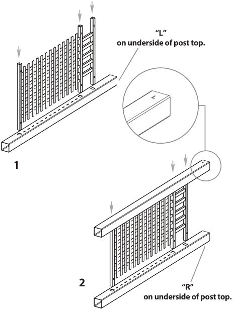
STEP FOURAttach Side Panels to Posts
1. Set out one post and complete the side panel by inserting the side panel assembly into the holes on the post. Push rails until the tabs snap into place.
2. Repeat for the adjacent post. Note that there is a Left and Right post. They are marked at the top of the post.
Each side panel should have a Left and Right post.
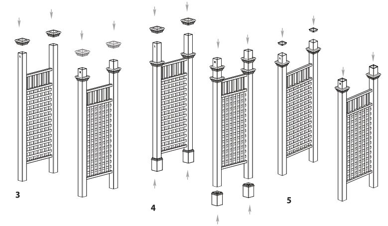
STEP FIVEAttach Trim Caps to Posts
3. Slide trim caps into place as illustrated.
4. If you purchased the Trim Kit (sold separately), also slide the second set of trim caps and base moldings at this point.
5. Glue and insert post caps on top of posts as illustrated
STEP SIXConnect the Pergola Top to the Posts
- Move side panels to their final location and adjust the opening width to 80 in. (203.2 cm.).Place the pre-assembled arbor top onto the post as illustrated.
- Fasten the main carrying beams onto the posts using two screws per side as illustrated .
- Fasten the rafters to the posts using two screws per side as illustrated.
Note: To glue the post trims in place:
1. Slide the post trim down.2. Apply a generous amount of vinyl glue around the post.3. Slide the post trim back up to desired location and allow a few minutes to cure.
STEP SEVENInstall the Arbor into the Ground
You have Three Options to Complete this Step. (All purchased separately)
OPTION ONE – If Your Arbor:• is going to be installed with fencing or a gate• is located in a high wind or hurricane area• is located in ground conditions that are not level
Consider Using:
A – 4×4 Professional Post Extension Kit (30 in./76.2 cm. long), (Kit of 4)• Purchase from Vita, www.wearevita.com• Recommended to be installed in concrete footings• Follow instructions included with the kit
– or –
B – 4 x 4 x 3’ (91.4 cm.) Long Wood Post (4)• Purchase separate from your local lumberyard• Recommended to be installed in concrete footing
OPTION TWO – If Your Arbor:• is intended to be used as a stand alone garden accent or pathway• is located on level ground
Consider Using:4” EZ Mount Post (Package of 4)
• Purchase from Vita, www.wearevita.com• Instructions are included with the kit
Into Earth with Concrete Footing (Option One)(Assuming posts have been extended )
Arbors must be well secured to prevent tipping over from wind load, etc.
- Move the arbor to its final location (you will need a helper).
- When you have identified the location of each post, mark the positions of the ground and then move the arbor aside.
- Excavate four holes approx 33 in. (83.8 cm.) deep. The location and excavation of these four holes is the most critical step and should be completed with care. The depth of these holes will allow the post extension (if chosen as option) joint to be hidden 3 in. (7.6 cm.) under the ground.
- Carefully move the arbor back into position and level both horizontal and vertically.
- Backfll the holes with either gravel or cement

![]()
North America Toll Free Phone: 1 800 282 9346www.wearevita.com
References
[xyz-ips snippet=”download-snippet”]