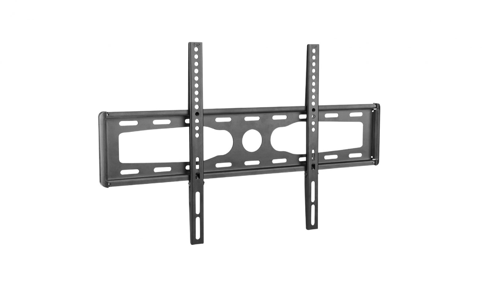
VITAL 37-70 Fixed TV Mount Instruction Manual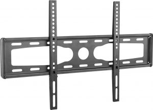
WARNINGS:
- Please read these instructions before you begin. If you are unsure of any part of the installation process, contact a professional contractor or installer for assistance. Improper installation can result in injury or damage.
- The wall or mounting surface MUST be capable of supporting the combined weight of the mount and the TV; if not, the structure MUST be reinforced
- Before drilling, locate pipes, wires or any other hazards in the wall where you want to install the mount
- Safety gear and the proper tools MUST be used. Failure to do so may result in injury or damage
- A minimum of two people are required for installation. DO NOT attempt to install this mount alone under any circumstances
- Follow all instructions and recommendations regarding adequate ventilation and suitable locations for mounting your 1V. Consult your Ns owner’s manual for more information
- CAUTION: This wall mount is intended for use only with the maximum weight of 45kg (991bs). Use with heavier than the maximum weights indicated may result in instability causing possible injury
TOOLS REQUIRED:
- Phillips head screwdriver
- Electric or portable drill
- 3mm (1/81 drill bit and stud finder for drywall installation
- 8mm (5/16″) masonry bit for concrete installation
- Tape measure
- Level
- Pencil
WHAT’S INCLUDED:
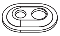
- 1 wall plate
- 2 mount arms
- 1 hardware kit
- 1 instruction manual
SPECIFICATIONS
TV Size Range: 37-70″Maximum Loading Capacity: 60kg (132Ibs)Vesa Mounting Pattern:MM: 200 x 200 mmMax: 600 x 400 mmProfile: 2.9cm (1.1 in)
Hardware Kit:
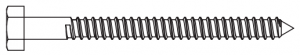
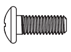
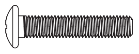
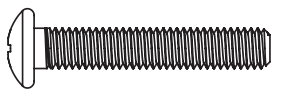
- (A) M6.3 x 50 Lag bolt (x4)

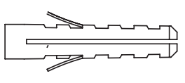
- (B) Concrete anchor (x4)
- (C) Washer (x4)
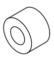
- (D) Spacer (x8)
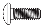
- (E) M6 x 12 Screw (x4)
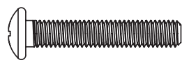
- (F) M6 x 30 Screw (x4)
- (G) M8 x 12 Screw (x4)
- (H) M8 x 30 Screw (x4)
- (I) MS x 12 Screw (x4)
- (J) M5 X 30 Screw (x4)
INSTALLATION
Part 1A – MOUNTING TO WALL (DRYWALL)
IMPORTANT! For safety reasons, this mount MUST be secured to at least two wood studs no less than 16″ apart. The studs MUST be capable of supporting the combined weight of the mount and display. DO NOT mount to drywall alone.
- Use a high quality stud finder to locate two adjacent studs where you want to install your mount. Mark both edges of each stud to help identify the exact center.NOTE: You must use the center of each stud to avoid cracking or splitting the wood during installation
- Place the wall plate against the wall with the arrow pointing up and level it using the integrated bubble level.
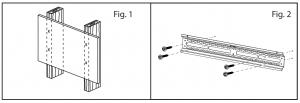
- While another person holds the wall plate in position, mark four locations (two per stud) for securing the mount to the wall. (Fig.1)
- Set the wall plate aside and drill a 3mm (1/8″) pilot hole at each marked location.
- Place the wall plate back against the wall and attach it using the lag bolts (A) and lag bolt washers (C) provided (Fig. 2). DO NOT over-tighten these bolts and DO NOT release the wall plate until both bolts are in place. Ensure that the wall plate remains level.
Part 1 B – MOUNTING TO WALL (CONCRETE)
IMPORTANT! For safety reasons, the concrete wall MUST be capable of supporting the combined weight of the mount and the display. The manufacturer takes no responsibility for failure caused by walls of insufficient strength.
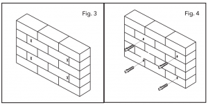
- Place the wall plate against the wall in the desired location with the arrow pointing up and level it using the integrated bubble level.
- While another person holds the wall plate in place, mark four locations on the wall for securing the mount (Fig. 3).
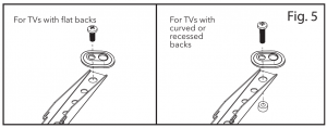
- Set the wall plate aside and drill a 8mm (5/16″) hole at each marked location. Remove any excess dust from the holes.
- Insert a concrete anchor (B) into each hole so that it is flush with the concrete surface (Fig. 4). A hammer can be used to lightly tap the anchors into place if necessary. NOTE: The concrete anchor must pass through anything that is over the concrete-i.e. plaster or drywall-and be completely flush with the surface of the concrete.
- Place the wall plate back against the wall and attach it using the lag bolts (A) and lag bolt washers (B) provided (Fig. 2). DO NOT over-tighten these bolts and DO NOT release the wall plate until both bolts are in place. Ensure that the wall plate remains level after tightening the bolts.
Part 2 – ATTACHING THE MOUNT ARMS TO THEN
IMPORTANT! Use extra care during this part of the installation. Avoid placing your N facedown as it may damage the viewing surface.NOTE: This mount comes with a selection of different screw diameters and lengths to accommodate different N models. Not all of the hardware in the kit will be used. If you cannot find the appropriate screw size in the kit provided, consult the manufacturer of your TV or a professional installer for more information.
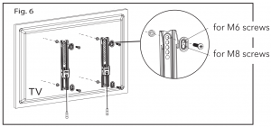
- Determine the correct length of screw to use by examining the back of your TV:
- If the back of your TV is flat and the mounting holes are flush with the surface, you will use the shorter screws (E, G or I)
- If the back of your Ti is curved, has a protrusion or if the mounting holes are recessed, you will need to use the longer screws (F, H or J) and may also need to use the spacers (D)
- Determine the correct diameter of screw to use by carefully trying one of each size (M5, M6 and M8) from the hardware kit. DO NOT force any of the screws. If you feel resistance STOP IMMEDIATELY and try a smaller diameter screw.
- Attach the mount arms to the back of your N using the screws identified in steps 1 and 2 (Fig. 6).
- If you are using the M5 or M6 screws you will need to use the smaller diameter hole of the washer (C). If you are using the M8 screws you will need to use the larger diameter hole.
- If you are using the longer screws on a TV with a curved or recessed back, you may also need to use the spacers (D). Use one spacer or two spacers stacked as needed. Only use a spacer if necessary.
- If you are using the M5 or M6 screws you will need to use the smaller diameter hole of the washer (C). If you are using the M8 screws you will need to use the larger diameter hole.
PART 3 – FINAL ASSEMBLY
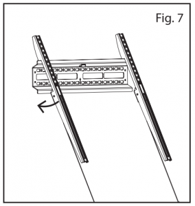
- With the help of another person, carefully lift your TV and place it on the wall plate. Gently apply pressure to the bottom of your TV so that the clips on the mount arms lock to the wall plate (Fig. 7). DO NOT release the N until the mount arms have securely hooked onto the wall plate.IMPORTANT! Verify that both arms are locked to the wall plate. For safety reasons, this mount CANNOT be used unless both arms are securely locked.
- Periodically clean your mount with a dry cloth. Inspect all screws and hardware at regular intervals to ensure that no connections have become loose over time. Re-tighten as needed.
- To remove your TV from the wall, pull down on both cables to unlock the arms and carefully lift the N from the wall plate.
 IMPORTANT! Verify that both arms are locked to the wall plate. For safety reasons, this mount CANNOT be used unless both arms are securely locked.
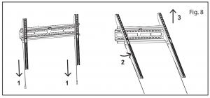
![]() WarningThis product contains small items that could be a choking hazard if swallowed. Keep these items away from young children!
WarningThis product contains small items that could be a choking hazard if swallowed. Keep these items away from young children!
- Make sure these instructions are read and completely understood before attempting Installation. If you are unsure of any part of this installation, contact a professional installer for assistance.
- The wall or mounting surface must be capable of supporting the combined weight of the mount and the display: otherwise the structure must be reinforced.
- Safety gear and proper tools must be used. A minimum of two people are required for this installation. Failure to use safety gear can result in property damage, serious injury or death.
THE SOURCE – WARRANTY
The Source warrants that this product will be free from defects in materials and workmanship for a period of one (1) year from the date of purchase. Within this period, simply take the product and your proof of purchase to any The Source store or participating dealer and the product will be replaced (where available) without charge. Any product which has been subject to misuse or accidental damage is excluded from this warranty.
This warranty is only applicable to a product purchased through The Source company-owned stores or participating dealers in Canada where the warranty is included with the product. While this warranty does not confer any legal rights other than those set out above, you may have additional statutory rights which will vary under the laws of the various countries, states, provinces and other governmental entities in which The Source operates. This warranty is subject to all statutory rights you may have in Canada.
Imported by:The Source, Barrie, Ontario, Canada, L4M 4W5 Manufactured in China www.thesource.ca 2021 The Source All rights reserved.

[xyz-ips snippet=”download-snippet”]