![]()
vitrum WallZ-503 VI EU On-Off 6 Triac User Manual
INTRODUCTION
Purpose of this documentThis manual describes the most essential functions and technical specifications to helptechnicians to install, setup and control the device. The device is a Z-Wave Plus device ofthe Vitrum 2.0 product range.
Product descriptionThe Light Control is a Security Enabled Z-Wave Plus device being able to both control other Z-Wave devices and activate scenes in Gateways. The wall controller can be added to and operated in any Z-Wave network with other Z-Wave certified devices from other manufacturers.
The Light Control is a mains power, always listening device. As all non‐battery operated nodes within the network will act as repeaters, no matter the vendor is, to increase the network reliability.
The device is able to control other devices, not able to act as Z-Wave network controller. A security enabled controller is to be used to add or remove the device from the network and have all functionally from the device.
Main features of Light Controller
- Control lights directly using ‘ON’/’OFF’ buttons
- Control of groups of other Z-Wave devices using ‘ON’/’OFF’ buttons
- Activation of scenes in Gateways.
- Compatible with any Z-Wave or Z-Wave+ Controller.
- Supports Z-Wave network Security Modes S2 Unauthenticated
- Touch operated button with RGB back-light
- Based on Z-Wave consumption ® 500 module for wider coverage and higher data rate
- Very low standby power consumption
- Triac switching at zero crossing point of AC
- Easy installation
- Acoustic feedback at button press.
Visit www.vitrum.com site for the complete device list.
Safety and warnings
- Do not install the device connected to mains
- Installation and maintenance working with 100 to 240V mains power must be carried out only by authorized technicians with country specific knowledge of installation guidelines and norms and regulations
- The device must never be used without the front glass plate. It must be installed in a way that protect from accidental contact. During installation procedure, the dummy plastic cover must be left on.
- Use only insulated tools and disconnect the device from mains circuit breakers before and during any installation activity.
- This device is permanently connected to the mains thus implies it is mandatory to have an always accessible disconnect device (like a circuit breaker) incorporated in the general wiring of the building with at least 3 mm separation between contacts.
QUICK START
- Connect your device to mains
- Start add mode on your Z-Wave controller
- Start add mode on your device by pressing add button
- Set associations on your device from your controller
INSTALLATION
Before you startPlease read carefully this user manual before any installation.You will need available and ready to use:
- Small Phillips insulated (alternate) screw driver
- Small slotted insulated (alternate) screw driver
Package content
- 1 x Wall Metric mountable device
- 2 x Metric screw set
- 2 x Plastic screw set
- 1 x Protective shell
- 1 x short reference document (this manual)
Preparation
Remove carefully the device from the cardboard support.Keep this manual for further reference.
NoticeDispose cardboard box & holder, plastic bags and front plastic shell according to local recycling regulation. Box and holder are PAP recyclable, plastic bags are LDPE, front shell is PP.
Installing
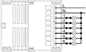
Wire the device according the schematic below.L Power connection (LIVE)N Power connection (Neutral)
Position the device in the wall’s mounting box and check cables are not interfering with the device case.Use the appropriate screw set that matches the wall box and fix the device in place without applying unnecessary torque to fix the screws.Do not locate the device facing direct sunlight, humid or dusty places.See suitable ambient temperature listed in the specifications.Do not place the device near combustible substances or sources of heat (e.g. fires, radiators, boiler, etc.)It’s strongly recommended to protect your device by adding a fuse on each output line.
Add the device to a certified Z-Wave network
The device supports both Classic Add (Classic Inclusion) and Network Wide Add (NetworkWide Inclusion).The device supports encryption S2 Unauthenticated.Follow the steps below to add the device to the network.
- Set primary controller into Add mode (please see controller instruction manual) and operate on it either to enable S2 Unauthenticated encryption or to disable encryption
- Check the device is not already added to the network (please refer to the manual section “How to check the device is added to the network”)
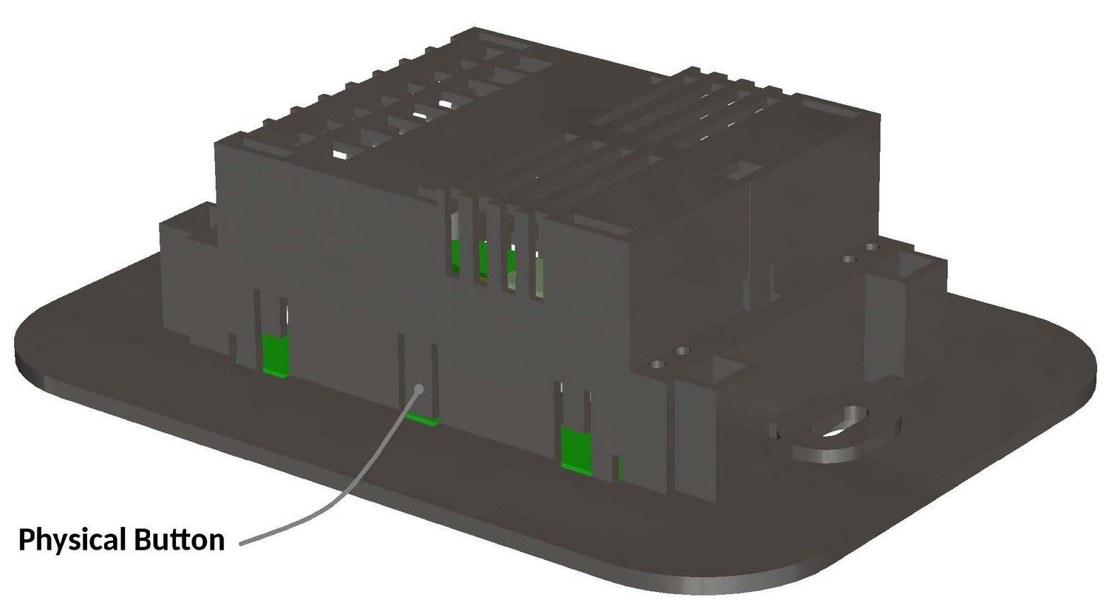
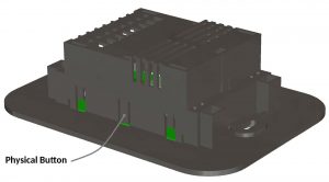
- Press and hold button N.1 located on top-left front-end device more then 4 seconds till button LED blinks shortly magenta or press shortly the Physical button located on the front-end top-back device (see section “Physical Button Operating” to locate Physical Button).
- Every device LED button blinks green shortly 3 times upon the device added successfully
Should the device fail the Classic Add (Classic Inclusion) the device enters into Network Wide Add (Network Wide Inclusion) mode up to 4 times. Any time the device enters into Wide Add Mode, LED Button N.1 blinks Magenta and keeps on to emit a short beep.
Remove the device from a certified Z-Wave network
- Set primary controller into Remove mode (please see controller instruction manual)
- Check the device is not already removed from the network (please refer to the manual section “How to check the device is added to the network”)
- Press and hold button N.1 located on top-left front-end device more then 6 seconds till the device emits a long beep. Release the button and press it shortly 3 times again or press shortly the Physical button located on the front end top-back device
- Button LED blinks red shortly upon the device removed successfully.
- Check the device is removed from the network (please refer to the manual section “How to check the device is added to the network”)
How to check the device is added to the networkPress button N.1 shortly. The LED button blinks red shortly whether the device is not added to the network.
ASSOCIATION (Single Channel and Multichannel)
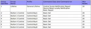
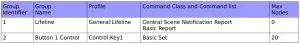
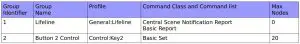
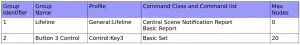
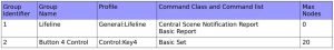
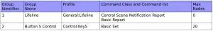
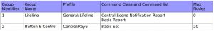
Association enables the device to control other nodes added to the same Z-Wave network. There are 7 association groups. Each group supports maximum 20 nodes for association.
Lifeline reportAdd Controller Node ID to the list of Node ID destinations belonging to the Lifeline Group,in order to let the controller receive Central Scene Notification report and Device Reset Locally Notification reports.
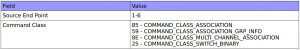
Lifeline report with End Point informationAdd both Controller Node ID and Controller End Point to the list of End Points belonging tothe Lifeline Group, in order to let the controller receive Central Scene Notification report with the End Point source address information. That may be achieved by sending the Multichannel Association Set Command Class and filling “Multi Channel Node ID” field with the Controller Node ID and “End Point” field with the Controller End Point.
Association groupsRoot Device
End Point 1
End Point 2
End Point 3
End Point 4
End Point 5
End Point 6
CONFIGURATION
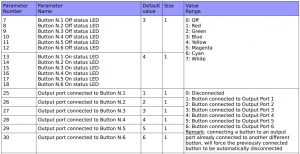
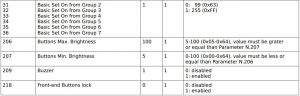
The device is configured according to the parameter list below.Use Configuration Get Command Class to get the current parameter value and Configuration Set Command Class to change the actual value. Get command should always be used before Set command to update the value.
Parameters list
DEVICE TYPE AND CAPABILITIES INFORMATIONS
Z-Wave+ InfoThis command class provides additional information about the Z-Wave Plus device.
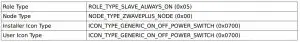
Node Information Frame (NIF)NIF contains information about the device type and the node capabilities.To send a NIF (broadcast) press and hold Physical button located on the front end topbackdevice, for over 2 seconds till the device emits two short beeps, than release the button. NIF is sent out upon the released of the button while the device emits a long beep.
NIF is also sent by setting the device either into Add or Remove mode.
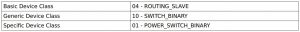
Device Class
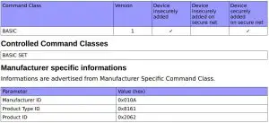
Supported Command Classes
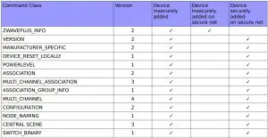
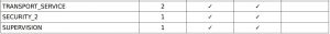
Supported Command Classes not in NIF
End Points
DescriptionEach endpoint is used by the device for:
- Switching directly light on/off
- Controlling a group of other Z-Wave devices
- Activation of “scene on” and “scene off” in Gateways
Root Device is mapped on End Point 1.
CapabilitiesCapabilities are advertised from Multichannel and Security 2 Command Classes.
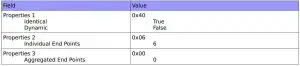
Multi Channel End Point Report
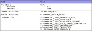
Multi Channel Capability Report (Device insecurely added)
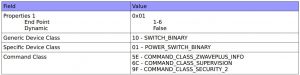
Multi Channel Capability Report (Device securely added)
S2 Commands Supported Report (Device securely added in secure net)
OPERATING
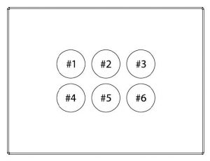
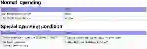
Buttons are numbered according to the picture below showing the front-end device. Each button has a back-light RGB LED showing different colors according to the operating status or reporting the status of a special condition.
Physical button operating
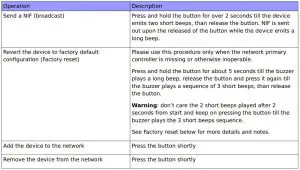
Factory resetDuring factory reset the device sends a Device Reset Locally notification from the Lifelinegroup.
The device reverts to its factory default settings, blinking all LED buttons and reboots andsend the Device Reset Locally Notification from the Lifeline group.Do not disconnect the device from power supply till rebooting is completed.Configuration and settings are restore to default values.Home ID and Node ID are cleared as well.
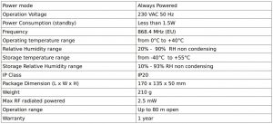
Specifications
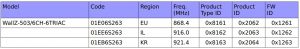
Models rangeThe WallZ-503/6CH-6TRIAC belongs to the below models range
Compliance with EC DirectivesThis device is built in compliance with the European directives EMC:2004/108/CE andR&TTE:1999/5/CE.
The manufacturer assumes no responsibility for any use not indicated in this manual.The manufacturer reserve the right to modify the product at any time and without notice in order to improve its quality and functionality. Therefore any information given in this user manual is subject to be modified. Please check for update at www.vitrum.com.
References
[xyz-ips snippet=”download-snippet”]