
Vive MOB1019 All Terrain Knee Walker Owner’s Manual

WHAT’S INCLUDED
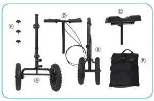
A Front FrameB Rear FrameC Knee PadD Steering Column/Handle Bars (attached by wire to the Front Frame)E Storage BagF 3x Screw Knobs
OVERVIEW
We are constantly answering questions and recording helpful videos to make using your Vive Mobility All-Terrain Knee Walker as easy as possible. Throughout the manualwe will include QR codes and links to important videos that you can visit to help you.
 To see all of the FAQs in one place visit vhealth.link/4e132
ASSEMBLY INSTRUCTIONS
Want to watch us do this? Check out vhealth.link/SaaOb l!l,for an easy instructional video.
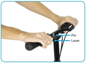
- Pull the steering column of the Front Frame ® to the vertical position. When in place, the silver pin running through the tension lever assembly will lock the two sections together.
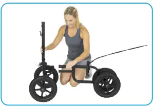
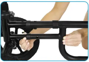
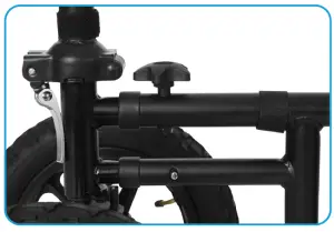
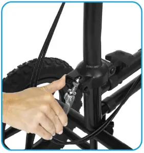
- Take the Front Frame ® and insert the 2 male ends into the female ends on the Rear . Push down the locking pins and push the frame pieces togetheruntil the locking pins engage and are locked in place.
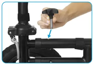
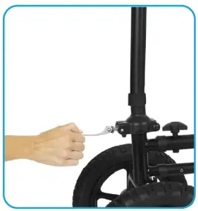
- Insert a Screw Knob® into the top of the frame above the locking pins and twist until fully tightened to secure the scooter wheelbase.
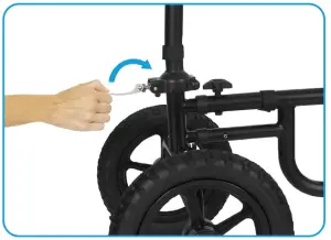
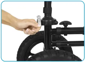
- Pull the silver tension lever assembly up until the lever and the spring bolt are vertical and parallel to the steering column socket.
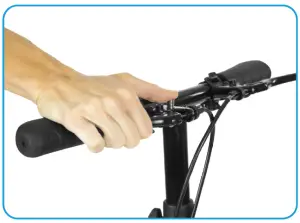
- 5. Pull just the flat silver lever back down to apply tension to the folding hinge and stabilize the front end of the scooter. If the silver lever does not apply enough tension, lift the lever back up, tighten the nut at the bottom of the spring bolt by half a turn, and retry pulling the lever back vdown. Repeat as necessary to ensure the lever provides enough tension.
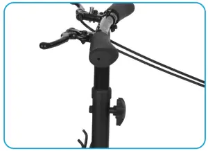
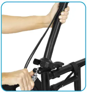
- Attach the handle bars to the steering column. Make sure that the brake line is not remove twisted around the bar.
- Adjust the Handle to the desired height making sure that the holes for inserting the Screw Knob® line up. Secure the handle bars with the Screw Knob®· Twist clockwise until fully tightened.
- Insert the Knee Pad© post into receptacle on the Rear Lock the pad in place by inserting a Screw Knob® into the desired adjustable height hole making sure that the holes for inserting the locking knob line up. Twist the knob clockwise until fully tightened.
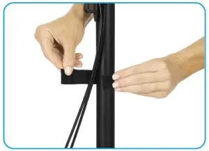
- Take the brake line and secure it inside the two fabric straps you will find on the top bar of the frame as well as the steering column.
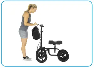
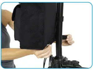
- To attach the Storage , locate the two hooks on the Front Frame @and the sleeve on the back of the bag. Insert the sleeve over the hooks. Attach thehook and loop fastener on the bottom of the bag to the steering column.


OPERATING INSTRUCTIONS
General Information
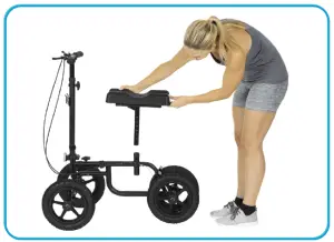
- Position your injured knee and leg firmly and securely in the middle of the knee pad, using the entire length of the pad to support your leg.
- While your knee is on the walker, stand as straight as possible. Adjust the height of the handlebars and the knee pad for comfort.
To Lock the Brakes
- follow the link here: vhealth.link/8ddf7
- Pull the hand brake lever in towards you to engage the brake.
- With the lever pulled in and the brake engaged, press the silver locking button down with your thumb.
- Hold the button down while releasing your grip on the brake lever. The pin will hold the tension on the brake cable and lock the brakes in place.
To Unlock the Brakes
- Pull on the brake lever until the silver locking button pops us, which release the tension on the brake cable and unlocks the brakes. Folding
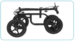
Folding the Steering Column
- Lift up the silver lever to release the tension in the folding hinge on the Front
- Rotate the silver lever and spring bolt assembly down.
- Pull the spring bolt assembly to the left to unlock the folding hinge, and push the steering column back to fold the handlebars down.Note: Removing the Knee Pad is optional. The handlebars can be tucked under the Knee Pad if desired.
SPECIFICATIONS
- Length: 31″
- Width: 16.5″ (at front wheels)
- Handlebar Height: 35 – 43″
- Wheels Diameter: 8″
- Weight: 20.75 pounds
- Knee Pad Length: 14″
- Knee Pad Width: 7″
- Knee Pad Adjustable Height: 18″ – 24″
- Maximum User Weight: 300lbs
WARNING
- Always consult with your physician/ therapist before use to determine proper adjustment and use. As with any new physical activity, common sense and practice are critical for the safe operation of the Knee Walker.
- Be sure you are on a level surface with the brake lock engaged when mounting/ dismounting the Knee Walker.
- The hand brake is designed to maintain the Knee Walker in a stopped position. The hand brake is not intended to be used for stopping the Knee Walker while in motion. Using the hand brake while in motion may cause an abrupt stop and a loss of stability in the device.
- Use caution when moving between floors/ surfaces with different textures (ex. moving from carpet to tile, or a concrete sidewalk to an asphalt street)
- Do not hang anything from the frame of the Knee Walker, as it may tilt the device off-balance.
- Do not adjust the screws/ bolts on the device unless otherwise specified in the instructions.
- Failure to properly secure the components will cause the Knee Walker to be unstable and difficult to control.
WARRANTY INFORMATION

Read More About This Manual & Download PDF:
[xyz-ips snippet=”download-snippet”]