
![]()
MOBILITYSMALL POWER WHEELCHAIROwner’s ManualMOB1029S

INTRODUCTION
The Vive Mobility Small Power Wheelchair is a versatile, motorized wheelchair that can be easily folded for storage or transport. Please read and follow all instructions, warnings, and notes in this manual before attempting to operate your Small Power Wheelchair for the first time. If there is any information in this manual that you do not understand, or if you require additional assistance for assembly or operation, please contact your local, authorized provider.Your Small Power Wheelchair consists of several components. The chair is foldable to allow for easy storage or transport. The operating system consists of a controller, battery well, two motors, a drive mechanism, and drive wheels.The battery is located under the seat base. The charging socket for the battery is on the back end of the controller. The wheelchair has two manual freewheel levers/brake levers on the drive mechanism.
OVERVIEW
We are constantly answering questions and recording helpful videos to make using your Vive Mobility Small Power Wheelchair as easy as possible. Check out the included links and QR codes to help you through the process

To see all FAQs in one place,visit vhealth.link/e60
WHAT’S INCLUDED

A lx chair frameB lx controlC lx power plugD lx charge blockE 2x footrestsF lx leg strap
ASSEMBLING THE POWER CHAIR
 For a video demonstration, check out: vhealth.link/lsc
- Remove the wheelchair from the packing box and put it on the ground in an open area.
- Push the chair frame apart, and press the two tubes on both sides of the seat base down into the grooves on each side of the chair frame.

- Pull up on the seatback handles and lock them into place.
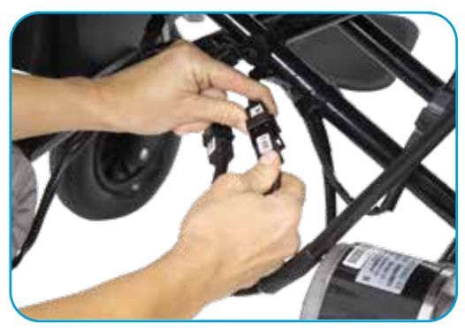
- Connect the wiring harness plug of the battery with the wiring harness socket from the frame.
- Unscrew the bolts and gaskets from the controller stem, set the controller in place over the plastic gaskets, secure the bolt by hand, then tighten by a screwdriver.
- Secure the wire harness to the frame using the supplied plastic cable ties.
- Connect the wiring harness plug of the controller with the socket harness socket from the batteries.
- Install the footplate tray on the upper tube of the left or right of the frame.
- Rotate the footplates forward so they can be automatically locked, then unfold the footplates.
- package the leg strap on the right and left upper tubes, then use the nylon tape.
- Adjust the height of the footplate, unload the safety nut on either side of the footplate, pull out the bolts, slide up and down the telescopic tube, position at a comfortable height, then insert the bolts and lock the nut.


OPERATING THE POWER CHAIR
For a video demonstration, check out: vhealth.Link/cqs
Charging the BatteriesWARNING: You must charge your wheelchair’s batteries with the charger supplied by Vive. Do not use any other type of battery charger.
To charge the wheelchair batteries:
- Be certain that the controller is turned off and the wheelchair brakes are applied.
- Connect the 3-pin metal plug of the charger into the 3-hole charger socket on the controller.
- Insert the plug of the charger into a wall electrical outlet.
- The red LED on the charger lights up, indicating that charging is in progress. The green LED on the charger lights when the batteries are fully charged.NOTE: A full charge will take approximately 8-12 hours.
- After charging is complete, unplug the charger from the wall outlet.
- Remove the output connector from the socket on the controller.
- Place the charger, cables, and plugs together in the bag on the rear seatback.


Overload ProtectorIn the event of a motor overload, the overload protector will shut down power to the wheelchair in order to protect the motors and their electrical elements. Please call your dealer directly for maintenance following a motor overload.Safety BeltFor safety purposes, please fasten the safety belt whenever seated in the wheelchair.
UNDERSTANDING THE POWER CHAIR CONTROLLER
The controller is a key component of the wheelchair. All electrical elements to operate the wheelchair are housed in the control panel. The controller consists of a joystick, battery gauge, an on/off button, a speed indicator, an accelerate button, a decelerate button, a horn button, and a charger socket.
The On/Off-Button controls power to the wheelchair. Don’t use the On/off button to stop the wheelchair unless some emergency occurs, as doing so may cause premature wear of the drive components.
The Joystick is mainly used to control the speed and direction of the wheelchair. The farther you push the joystick from its central position, the faster the wheelchair moves. Whenever you release the joystick, it will automatically go back to the central position and the brake will be automatically operative.
WARNING! If your wheelchair moves accidentally, immediately release the joystick so that the wheelchair will stop moving automatically.
The Horn is a safety feature that will create an audible warning sound if you press the button.
The Speed Up/Down Buttons control the speed of the wheelchair. After turning on the power, the speed light will indicate the speed setting. The maximum speed range showed by the number of light cells can be adjusted by users. Each time the Speed Up Button (or Speed Down Button) is pressed, the speed will increase (or decrease) a light cell.
The Brake Lever secures the
wheelchair in place. To park the wheelchair, pull the brake lever back.
Note: When parked on a sloped surface, the brake lever must be pushed forward, otherwise the wheelchair will lose control and result in personal injury.
The Safety Belt should be worn at all times when seated in the wheelchair.
SHUTDOWN PROCEDURE
When not in use, the wheelchair should be shut down according to the following instructions:
- Turn off the power and unplug all wiring connections.
- If cleaning is desired, use a clean, soft cloth to scrub, then dry the wheelchair frame.
- Store the wheelchair at room temperature in a dry environment.
FOLDING THE CHAIR FOR TRANSPORT OR STORAGE
To fold the wheelchair for transport or storage:
- Turn off the power.
- Turn the footplates up and rotate outward 90 degrees.
- Turn the leg lever holder outward, rotate it 90 degrees, then pull out the leg lever.
- Pinch both folding levers on both sides of the push-handle, and flip down the push-handle.
- Pull the seat base up in the middle to fold the wheelchair.


ROUTINE CHECKS
The wheelchair should be inspected before use to assure it remains in optimal operative condition. Refer to the Routine Maintenance Checks table found in the Care and Maintenance section of this manual for detailed guidance.
TROUBLESHOOTING
This wheelchair is equipped with a malfunctioning auto alarm. If the wheelchair experiences a failure, the LED lights on the controller will turn on and a buzzer will sound.Please consult your authorized agent for service if any faults still occur after troubleshooting.
| Number of Alarm | LED Display | Diagnosis |
| 1 | 1 LED light illuminates | Battery is low |
| 2 | 2 LED lights illuminate | Left side motor failure |
| 3 | 3 LED lights illuminate | Left side brake failure |
| 4 | 4 LED lights illuminate | Right side motor failure |
| 5 | 5 LED lights illuminate | Right side brake failure |
| 6 | 6 LED lights illuminate | Controller overload |
| 7 | 7 LED lights illuminate | Joystick failure |
| 8 | 8 LED lights illuminate | Controller failure |
| 9 | 9 LED lights illuminate | Controller failure |
SPECIFICATIONS
| Overall size (L x W x H) | 1005 x670 x 960mm (39.5 x 26 x 38 in.) |
| Seat height | 520mm (20.5in.) |
| Seat width | 410mm (161n.) |
| Seat depth | 450mm (181n.) |
| Armrest height | 200mm (8in.) |
| Backrest height | 410mm (1634in.) |
| Battery weight | 14kg (30.861bs) |
| Wheelchair Weight with Battery | 43kg (951bs) |
| Maximum speed | 6km/h (4mph) |
| Braking Distance at 6km/h | S1500mm (60in.) |
| Maximum Turning Radius | 51200mm (47n.) |
| Payload Capacity | 100kg (2201bs) |
| Theoretical Range Per Charge | 20km (12 miles) |
| Static Stability | >ge |
| Dynamic Stability | 213° |
| Climbing Ability | 6′ |
| Motor Specification | 24V/250W x 2 |
| Battery Specification | 12V/20Ah x2 |
| Maximum Current Output of Controller | 50A |
| Current Output of Batteries | 2A |
| Front Wheel | Inflate-free tires.
The outside diameter of 190mm |
| Rear Wheel | Pneumatic tires,
The outside diameter of 398mm |
CARE AND MAINTENANCE
If the batteries, joystick, motor/drive, charger, or other serviceable parts are in need of repair or replacement, please contact the dealer directly.
Routine Maintenance Checks
| Items | Always | Weekly | Monthly | Semi-Annually |
| Each part | X | |||
| Turning, Driving, Preset and Disassembly | X | |||
| Brakes | X | |||
| Wiring Harness and Cables | X | |||
| Charging of Batteries | X | |||
| Mobility of the Front Wheels | X | |||
| Pneumatic Case of the Rear Wheels | X | |||
| Tire Wear | X | |||
| Tire Damage | X | |||
| Wear of the Push-Handle, Seatback, and Seatbase | x | |||
| Motors | X | |||
| Controller | X | |||
| Cleanliness | X |
WARNINGS AND PRECAUTIONS
- Make sure that the controller has been reliably installed and the joystick is in a vertical position.
- Sit firmly, fasten the safety belt a lean against the backrest with your head raised during operation.
- After turning on the power, check the speed indicator to ensure a proper It is advised to set the speed at the lowest setting at start-up, and gradually increase to the desired level.
- If the wheelchair moves in an unexpected direction, release the joystick immediately.
WARNING: Keep feet within the footplates at all times when seated in a wheelchair.
WARNING: Do not extend arms out of the armrests during operation.
WARNING: Ensure the wheelchair brake is applied before operation and before exiting the chair.
Hazards
Do not use the wheelchair under the following circumstances:
- In instances prohibited by this user’s manual. For instance, use above maximum allowed incline, too high of barriers, highways, motor vehicle lanes, etc.
- On slippery, sloped, or another unstable terrain.
- If any componentry is in need of repair.
Electromagnetic Interference
WARNING: Electronic equipment can be affected by Electromagnetic Interference (EMI). Such interference may originate from radio stations, TV stations, mobile phones or other radio transmitters. If the wheelchair has abnormal operation due to electromagnetic interference, shut down the power and consult the wheelchair dealer. The company does not take any legal responsibility for loss caused by failure to comply with this condition.
WARRANTY INFORMATION
- 3-year warranty on the chair frame.
- 1-year warranty on the following:a. Electrical control/lever systemb. Motor/Drive Systemc. Bearing and shaft sleeve
- 6-month warranty on batteries.
- The following components are not covered by warranty:a. ABS plastic cover shell and rubber padb. Tirec. Interior decorationd. Damage by abuse, wrong operation, accidents, or negligencee. Business use or other abnormal use
[xyz-ips snippet=”download-snippet”]