![]()
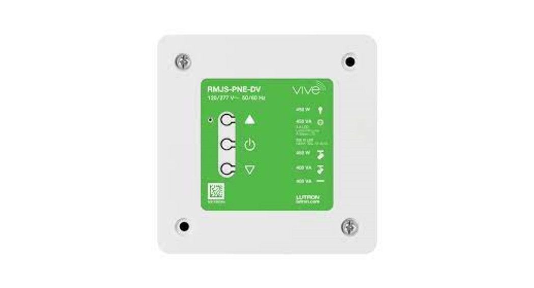
Vive InstallationVive PowPak 347 V~ Relay ModuleVive Emergency PowPak 347 V~ Relay ModulePart of the Vive FamilyRMJS-5R-347RMJS-5R-347-EM347 V~ 60 Hz 5 Anon-dim electronic ballasts and LED drivers only
 041828Rev. A08/2021
Important Notes: Please read before installing.For installation by a qualified electrician in accordance with all local and national electrical codes.
- Note: Use copper conductors only.
- Check to see that the device type and rating is suitable for the application.
- DO NOT install if the product has any visible damage.
- If moisture or condensation is evident, allow the product to dry completely before installation.
- Operate between 0 °C and 40 °C (32 °F and 104 °F) ambient.
- 0% to 90% humidity, non-condensing.
- For indoor use only.
- This is intended to be used only on 347 V~ non-dim electronic lighting loads.
- For application note, see [PDF]For spec submittal, see [PDF]
IMPORTANT SAFEGUARDS
When using electrical equipment, basic safety precautions should always be followed including the following:READ AND FOLLOW ALL SAFETYINSTRUCTIONS
- Do not use outdoors.
- Do not mount near gas or electric heaters.
- Equipment should be mounted in locations and at heights where it will not be subjected to tampering by unauthorized personnel.
- The use of accessory equipment not recommended by the manufacturer may cause an unsafe condition.
- Do not use this equipment other than its intended use.
SAVE THESE INSTRUCTIONS
![]()
All Wireless Transmitters must be installed within 9 m (30 ft) of the Relay Module.
Default FunctionalityOccupancy Sensors
 Occupied: All lights 100%.Unoccupied: All lights off.
Daylight Sensor
 All lights turn on / off in response to daylight.
Wireless Controls
| On | All lights 100% |
| Off | All lights off |
System Components Customer Assistance www.lutron.com/supportAt least one non-dim Fluorescent Ballast or LED DriverConsult third-party fixtures installation guide for fixture-specific wiring.
 Switches up to 5 A total.Note: All drivers and ballasts used with Vive wireless controls must comply with the limits pursuant to CAN ICES-005 and the FCC rules.
Start Here
- Mount, Wire, and Install Devices and
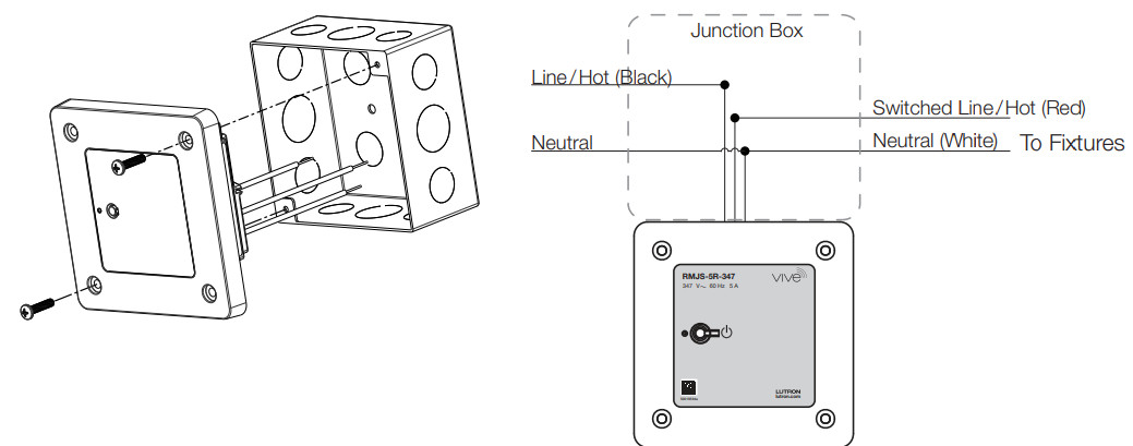
Lighting FixturesConsult the third-party device installation guide WARNING! Shock Hazard. May result in serious injury or death. Turn off power at the circuit breaker before installing the unit.A Connect mains wiring (switched hot, neutral) to each fixture.NOTE: Output must NOT be used to control receptacles. Output must be directly connected to the load. Output breakers or switches must not be used.
2. Install Relay Module
Suggested Installation Location: Center of room to ensure proper RF coverage of the area. For optimal RF performance:
- The module must not be fully enclosed in metal.
- No metal should exist anywhere within 200 mm (8 in) in front of the front plate of the module.
- Mount module a minimum of 0.6 m (2 ft) away from any lighting fixture.
- Ensure the junction box is well-grounded (preferably via a metal conduit between the controlled fixture and the module junction box).
A. Relay Module must be installed in a metal 101.6 mm x 101.6 mm (4 in x 4 in) junction box (minimum depth 54 mm (2.125 in) with mounting screws (provided). Please consult local and national electric codes for proper installation. Note: if the module cannot be fully seated into the junction box, try rotating the module 90, 180, or 270 degrees. Or move conduit hardware to a different knockout hole. If neither option works, an extension ring may be required. See 048753 on www.lutron.com for more information.B. Connect bare copper wire from the junction box to the green ground screw.C. Once installed, energize the Relay Module.D. Use the Toggle button “ u” to toggle between high-end and OFF to verify ballasts or LED drivers wiring.
Wire Connector Information
 |
13 mm (1/2 in): 4.0, 2.5, & 1.5 mm2 (10, 12, & 14 AWG)16 mm (5/8 in): 1.0 & 0.75 mm2 (16 & 18 AWG) | (1-3 4.0 mm2 10 AWG)(1-3 2.5 mm2 12 AWG)(1-3) 1.5 mm2 14 AWG)(1-2) 4.0 mm2 & (1) 2.5 mm2 (10 & 12 AWG)(1-2) 4.0 mm2 & (1) 1.5 mm2 (10 & 14 AWG)(1-2) 2.5 mm2 & (1) 1.5 mm2 (12 & 14 AWG)(1-2) 4.0 mm2 & (1) 1.0 mm2 (10 & 16 AWG)(1-2) 2.5 mm2 & (1) 1.0 mm2 (12 & 16 AWG)(1-2) 1.5 mm2 & (1) 1.0 mm2(14 & 16 AWG)(1-2) 4.0 mm2 & (1) 0.75 mm (10 & 18 AWG)(1-2) 2.5 mm2 & (1) 0.75 mm2 (12 & 18 AWG)(1-2) 1.5 mm2 & (1) 0.75 mm2 (14 & 18 AWG) |

Note: RMJS-5R-347-EM requires the use of an automatic transfer switch to change from normal to emergency power. Refer to 048628 for wiring diagrams on www.lutron.comIf installing an emergency Relay Module and the wiring needs to be verified, follow the “Reset Factory Defaults” procedure to exit emergency mode.Please note that any programming will be lost and will have to be reprogrammed. Only perform this step during initial installation and wiring verification.Note: For periodic testing and maintenance of emergency systems, use the toggle button to ensure proper operation. Make sure buttons remain accessible.Note: Momentary power outages can envoke emergency mode on the Relay Module. SeeTroubleshooting section for details.
Programming with a Vive Hub
The Vive hub can be set up easily with any Wi-Fi enabled iOS® or Android® compatible device.A.Download the Lutron Vive app.
B. Open the app and follow the instructions.
Note: For further information on set up, programming, and troubleshooting with a Vive system, please refer to the installation instructions included with the Vive hub or visit www.lutron.com/viveNote: For programming, the Relay Module without a Vive hub sees the reverse side.
Programming without a Vive HubRelay Module
1.Associate Wireless Transmitters toRelay ModuleBefore beginning this step, make sure that there are no other relay Modules or any other modules being set up within the same building. It is possible that wireless transmitters from other systems can be incorrectly associated to this module.
A On Relay Module, hold the Toggle button “ ![]() ” for 6 seconds until lights flash.The indicator LED will begin flashing twice per second.
” for 6 seconds until lights flash.The indicator LED will begin flashing twice per second.
B Hold the indicated button on each transmitter for 6 seconds.
![]()
C On Relay Module, hold the Toggle button “ ![]() ” for 6 seconds to save association. Lights will flash and LED will quickly blink for 2 seconds.
” for 6 seconds to save association. Lights will flash and LED will quickly blink for 2 seconds.D Permanently install wireless transmitters (consult individual component installation guides for information).
Reset Factory DefaultsNote: In some instances, it may be necessary to reset the Relay Module and connected devices back to factory default settings. Before beginning, make sure that all devices areconnected and powered.A Triple-tap the Toggle button “ ![]() ” on the Relay Module and hold until the LED begins to flash slowly; release button.B Within 3 seconds of the start of flashing, triple-tap the same button again and the LEDs will flash rapidly indicating that the unit has been reset to factory defaults.Note: Any associations or programming previously set up with the Relay Module will be erased and will need to be re-programmed.
” on the Relay Module and hold until the LED begins to flash slowly; release button.B Within 3 seconds of the start of flashing, triple-tap the same button again and the LEDs will flash rapidly indicating that the unit has been reset to factory defaults.Note: Any associations or programming previously set up with the Relay Module will be erased and will need to be re-programmed.
2. Calibrate the Radio Power Saver Daylight SensorDaylight Sensor will control all wired fixtures equally.
A Initiate calibration setup when the room is receiving the desired amount of light.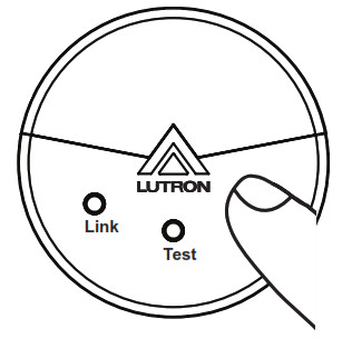 Press and release the “Cal.” button on the Daylight Sensor.B Turn lights in the room on using the Toggle button on the Relay Module or any other modules.C Press and hold the “Cal.” button for 6 seconds.D Exit room for 5 minutes to complete calibration.Note: When calibration has completed, all lights will flash and begin to respond to daylight.
Multiple Daylight Rows (Optional)For every row of daylighting, a separate Relay Module must be used. For a detailed setup refer to the tuning section of the Radio Power Savr Daylight Sensor installation guide.
- Select the Relay Module that you want to adjust by pressing the toggle button.
FCC/ IC Information:This device complies with part 15 of the FCC Rules and Industry Canada license-exempt RSS standard(s). Operation is subject to the following two conditions:(1) This device may not cause interference, and(2) this device must accept any interference, including interference that may cause undesired operation. Modifications not expressly approved by Lutron Electronics Co., Inc. could void the user’s authority to operate this equipment.Note: This equipment has been tested and found to comply with the limits for a Class B digital device, pursuant to part 15 of the FCC Rules. These limits are designed to provide reasonable protection against harmful interference in a residential installation. This equipment generates, uses, and can radiate radio frequency energy and, if not installed and used in accordance with the instructions, may cause harmful interference to radio communications. However, there is no guarantee that interference will not occur in a particular installation. If this equipment does cause harmful interference to radio or television reception, which can be determined by turning the equipment off andon, the user is encouraged to try to correct the interference by one or more of the following measures:
- Reorient or relocate the receiving antenna
- Increase the separation between the equipment and receiver
- Connect the equipment into an outlet on a circuit different from that to which the receiver is connected
- Consult the dealer or an experienced radio/TV technician for help
Customer Assistance:U.S.A. / Canada: 1.844.LUTRON1www.lutron.com/supportLimited Warranty:
Customer Assistance www.lutron.com/support
Troubleshooting
| Ballasts or LED drivers cannot be controlled locally from Relay Module. | • Ensure that the breaker(s) to the Relay Module is energized.• Ensure that the Relay Module switched hot lead is wired to the lighting fixture(s).• Relay Module may be in emergency mode. |
| Reset to factory defaults. | |
| Lights do not respond to Wireless Transmitter(s) (Pico remotes and RPS sensors). | • Ensure that the breaker(s) to the Relay Module and any connected ballasts or LED drivers are energized.• Ensure that Wireless Transmitters are associated to the Relay Module. |
| Reset to factory defaults. | |
| Wireless Transmitter(s) cannot be associated to Relay Module. | • The maximum number of Wireless Transmitters have been associated to the Relay Module. To remove a previously set up Wireless Transmitter, see www.lutron.com/vivevideos |
Lutron, Pico, Radio Power Saver, and Vive are trademarks or registered trademarks of Lutron Electronics Co., Inc. in the US and/or other countries. Safari is a trademark of Apple Inc., registered in the U.S. and other countries. All other product names, logos, and brands are the property of their respective owners.© 2021 Lutron Electronics Co., Inc.
References
[xyz-ips snippet=”download-snippet”]