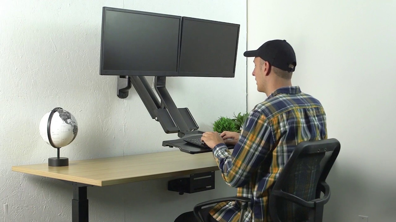

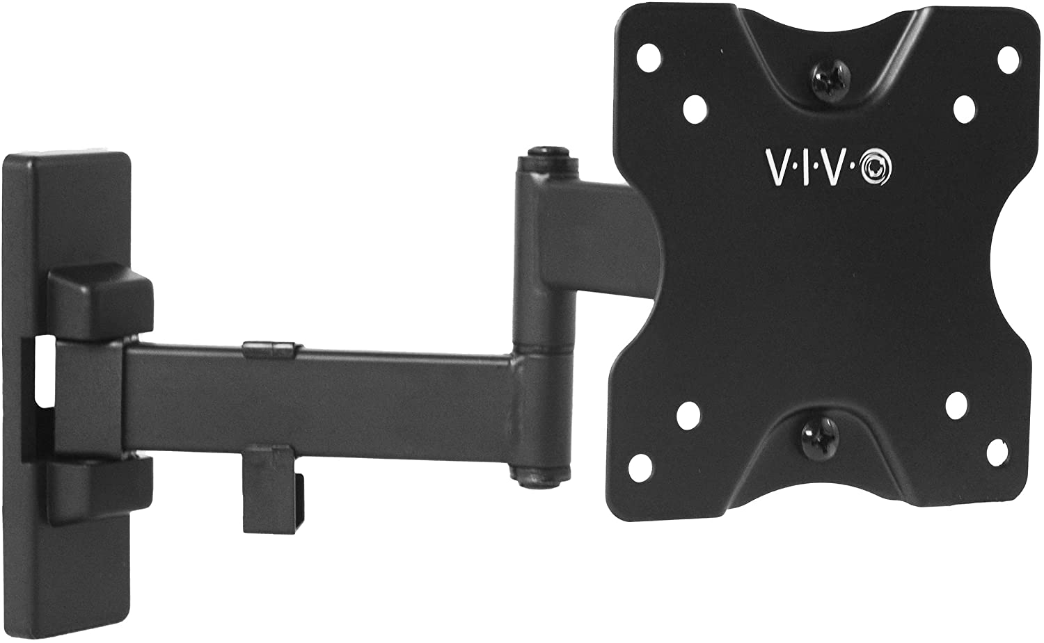
VIVO Single Monitor Wall Mount
WARNING!
If you do not understand these directions, or if you have any doubts about the safety of the installation, please call a qualified technician. Check carefully to make sure there are no missing or defective parts. Improper installation may cause damage or serious injury. Do not use this product for any purpose that is not explicitly specified in this manual. Do not exceed weight capacity.We cannot be liable for damage or injury caused by improper mounting, incorrect assembly or inappropriate use.
PACKAGE CONTENTS
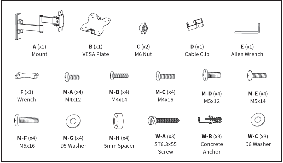
NOTE: NOT ALL HARDWARE INCLUDED WILL BE USED
CAUTION! DO NOT INSTALL INTO DRYWALL ALONE. VERIFY YOUR WALL CONSTRUCTION. USE WOOD STUDS TO MOUNT. We include mounting for brick and concrete walls. If unsure, please contact us at vivo-us.com, email at [email protected], or call us at 309-278-5303.
WARNING: CHOKING HAZARD SMALL PARTS – NOT FOR CHILDREN UNDER 3 YEARS. ADULT SUPERVISION IS REQUIRED.
ASSEMBLY STEPS
STEP 1: OPTION A: Wood Wall InstallationUse the mount (A) to mark drilling locations on the wall where a stud is located. Using a 3/16” bit, drill 2.2” deep holes into marked locations. Secure the mount (A) to the wall using ST6.3×55 screws (W-A) with washers (W-C).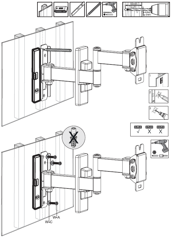
OPTION B: Concrete/Brick Wall InstallationUse the mount (A) to mark drilling locations on the wall. Using a3/8” bit, drill 2.4” deep holes into marked locations. Insert concrete anchors (W-B) into the holes and secure the mount (A) to the wall using ST6.3×55 screws (W-A) with washers (W-C).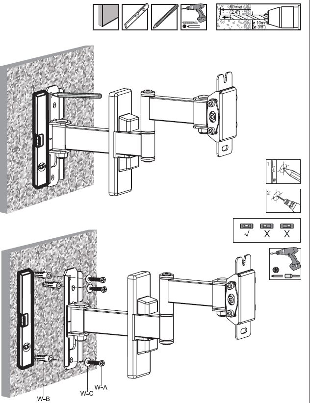
STEP 2: Attach the plastic cover to the wall plate of the mount (A).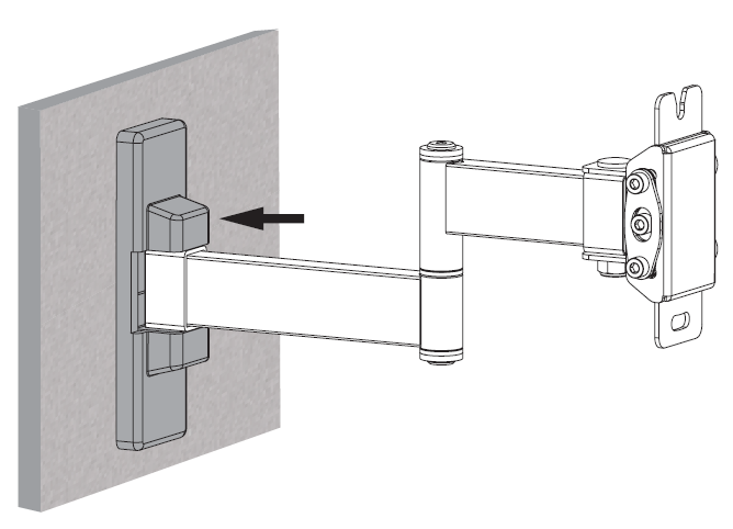
STEP 3: Attach the cable clip (D) to the arm (A) as shown.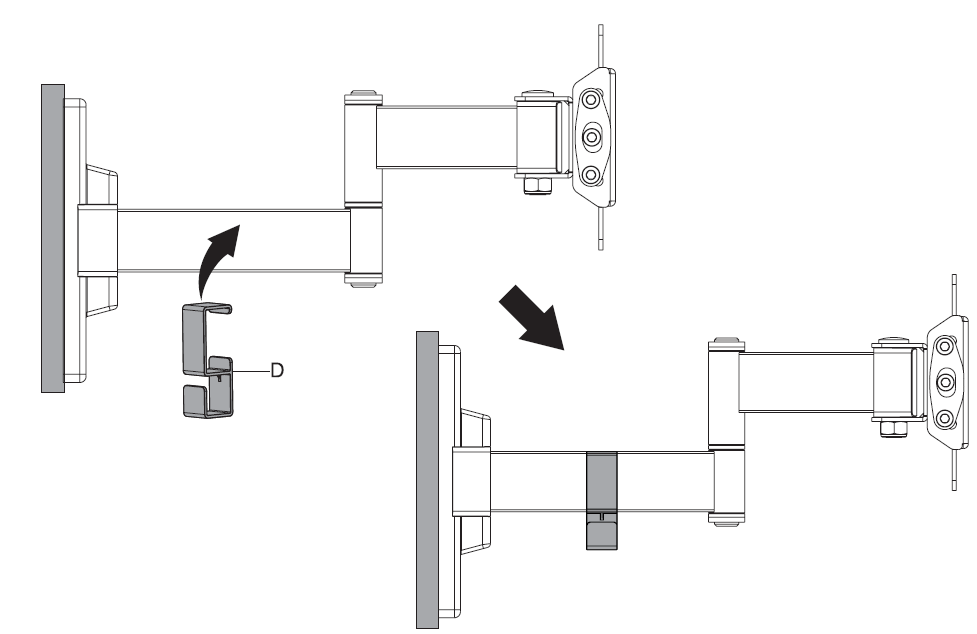
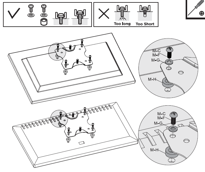
STEP 4:OPTION A: For Flat Back DisplaysInstall the VESA plate (B) to the back of the TV/monitor using 12/14mm length bolts (M-A, M-B, M-D or M-E) with D5 washers (M-G).
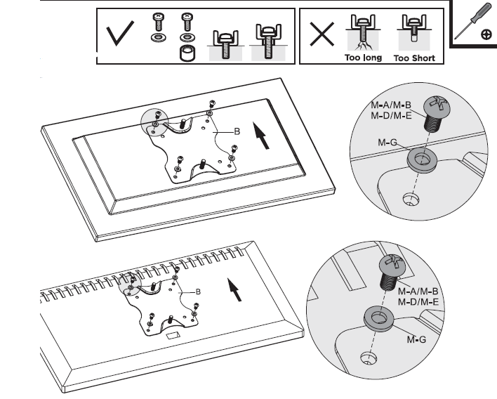
OPTION B: For Curved / Recessed Back DisplaysInstall the VESA plate (B) to the back of the TV/monitor using 16mm length bolts (M-C or M-F) with D5 washers (M-G) and spacers (M-H).
STEP 5: Partially install one M6 nut (C) to the top screw of the VESA plate (B) and hang over the slot in the top of the mount (A). Install the second M6 nut, then tighten both nuts.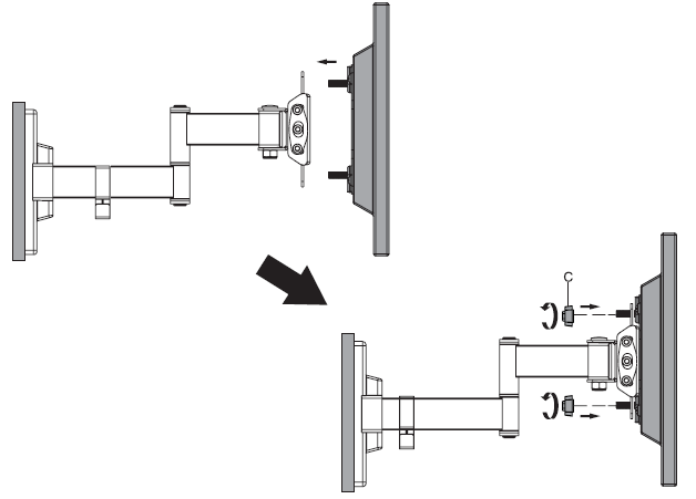
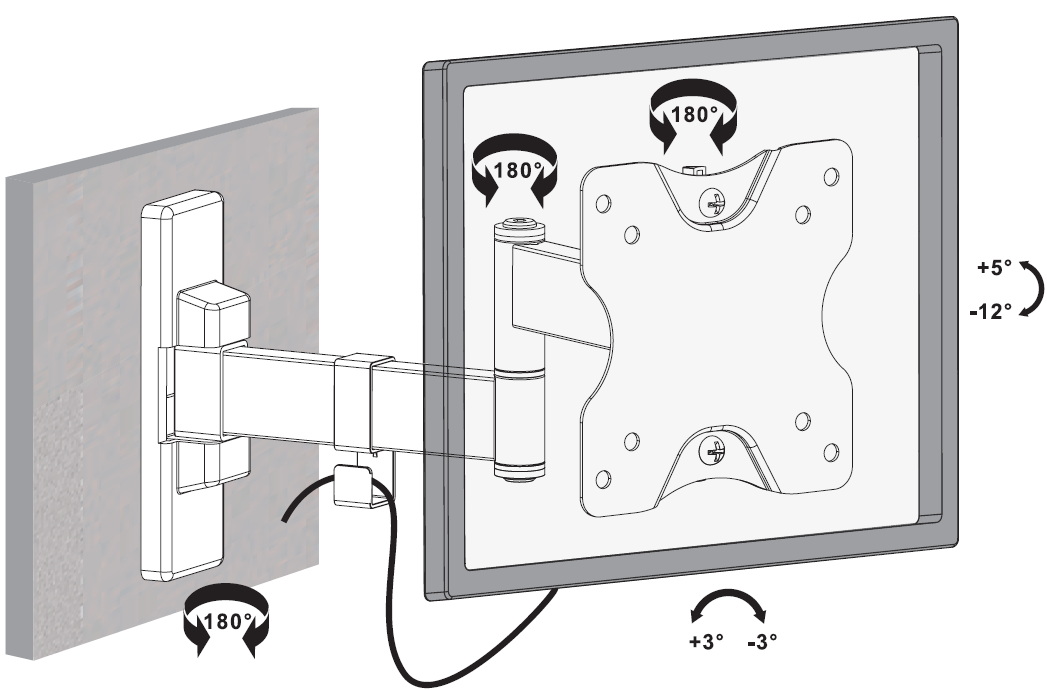
STEP 6: Adjust tilt support using the Allen wrench (E) and swivel joints using the wrench (F).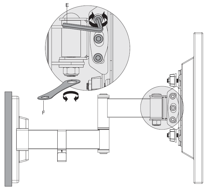
STEP 7: Organize cables using the cable clip (D).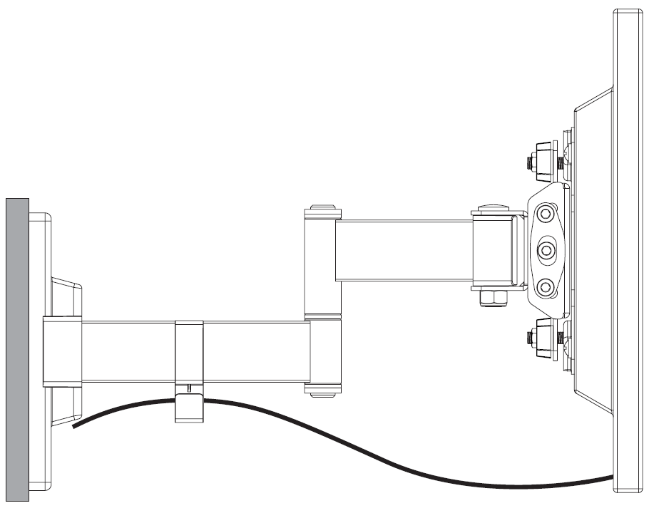
Adjust as Desired
Open Monday – Friday 7:00am – 7:00pm CST,our dedicated support team can offer immediate assistance with rapid response times. If any parts are received damaged or defective, please contact us. We are happy to replace parts to ensure you have a fully functioning product.
Email: [email protected]Live Chat: www.vivo-us.comPhone: 309-278-5303
FOR MORE VIVO PRODUCTS, CHECK OUT OUR WEBSITE AT: www.vivo-us.com
References
[xyz-ips snippet=”download-snippet”]