
True RMS Voltmeter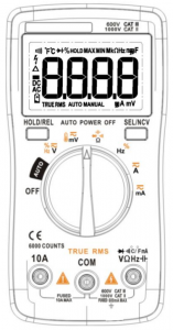
Thank you for purchasing our product.Please read this manual carefully before use.Please keep this manual properly after reading
Safety Instructions
Please read the following precautions carefully
![]() Caution There may be a risk of death or serious injury.
Caution There may be a risk of death or serious injury.
![]() Caution There may be a risk of personal injury or property loss.
Caution There may be a risk of personal injury or property loss.
- Do not input signals exceeds the measurement range of this product. Please select the correct test position and range to avoid damage to the instrument or personal injury. “
 ” will be shown on the display when out of range.
 - When the voltage to be measured exceeds 36V DC or 25V AC, the operator shall be careful to avoid electric shock.
- Check the function position before measuring.
- Disconnect the test leads from the circuit before changing the mode.
- For your safety, please read this manual carefully before use. Please fully understand the instructions and use this product correctly.
![]() Caution Do not measure circuits that exceed the maximum input rated value 1000V.
Caution Do not measure circuits that exceed the maximum input rated value 1000V.
Measurement Notices
Common Notice
![]() Caution
Caution
- DC/AC high voltage circuits are very dangerous, please becareful to measure.
- Do not to add AC/DC voltages that exceeds the maximumrated value between the ground terminal and test terminal.
- Do not add voltage that exceeds the allowable value.
- Do not operate this product with wet hands to avoid the risk of electric shock.
- Do not use the product around explosive gas, vapor, or in damp or wet environments.
- Do NOT touch the input terminals when measuring.
- Do not use test leads with damaged coatings.
AC/DC Voltage Measurement Notice
![]() Caution
Caution
- The measured voltage should not exceed the rated maximum test value, otherwise it may damage the product and endanger personal safety.
- Do not measure voltages that exceed the allowable value.
AC/DC Current Measurement Notice
![]() Caution
Caution
- The measured current should not exceed the rated maximum test value, otherwise it may damage the product and endanger personal safety.
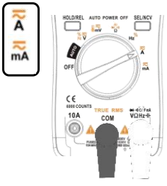
- Use the 10A Terminal and the Mode to judge range and choose the right function position when measure an unknown current.
- It is strictly forbidden to input voltage in this measuring state.
Resistance Measurement Notice
![]() Caution
Caution
- Before measuring the resistance, please make sure that all capacitors in the circuit to be measured are fully discharged.
- It is strictly forbidden to input voltage in this measuring stat
![]() Caution
Caution
- Please do not measure the continuity with a voltage circuit or wire.
- It is strictly forbidden to input voltage in this measuring state.
Other Notices
Battery Change Notice
![]() Caution
Caution
- Please turn off the power.
- Install the battery cover and tighten the screws before measuring.
Test Leads Notice
![]() Caution
Caution
Do not touch the pins of the test leads during the measurement. Do not use test leads with damaged coatings. Please do not stretch the cables to avoid breaking the test lead. Dust and water are not supported.
![]() Caution
Caution
Except for our company or our authorized individuals, please do not attempt to repair or modify the circuit board to avoid the danger caused by improper operation.
Introduction
This product is a multi-functional, auto-ranging digital multimeter with a 6000 counts LCD display.
- Measurement functions include AC/DC voltage, AC/DC current, resistance, diode test/continuity, NCV, frequency/duty cycle, capacitance.
- Support True- RMS
- Support Auto Power Off
- Support temperature measurement
- Support data hold
General Specifications
| Display (LCD) | 6000 counts |
| Ranging | Auto |
| Material | ABS/PVC |
| Update Rate | 3 times / second |
| Low Battery Indication | √ |
| Product Weight | 114g (batteries not included) |
| Product Dimension | 130*65*32mm |
| Operating Storage | Temperature | 0~40℃ |
| Humidity | <75% | |
| Operating Storage | Temperature | -20~60℃ |
| Humidity | <80% |
- Specifications are subject to change without notice.
- Batteries included are samples.
- Battery life may be shorter than regular commercial batteries.If the backlight and buzzer are used frequently, battery life will be shortened.
Electrical Specifications
| Function | Range | Resolution | Accuracy | Max |
|
DC Voltage (V) |
6.000V | 0.001V |
±(0.5%+3) |
1000V |
| 60.00V | 0.01V | |||
| 600.0V | 0.1V | |||
| 1000V | 1V | |||
| DC Voltage
(mV) |
60.00mV | 0.01mV | 600mV | |
| 600.0mV | 0.1mV | |||
|
AC Voltage (V) |
6.000V | 0.001V |
±(1.0%+3) |
750V |
| 60.00V | 0.01V | |||
| 600.0V | 0.1V | |||
| 750V | 1V | |||
|
AC Voltage (mV) |
60.00mV | 0.01mV |
600mV |
|
| 600.0mV | 0.1mV |
| Function | Range | Resolution | Accuracy | Max |
|
DC Current (A) |
6.000A | 0.001A |
±(1.2%+3) |
10A |
| 10.00A | 0.01A | |||
| DC Current
(mA) |
60.00mA | 0.01mA | 600mA | |
| 600.0mA | 0.1mA | |||
| AC Current
(A) |
6.000A | 0.001A |
±(1.5%+3) |
10A |
| 10.00A | 0.01A | |||
| AC Current
(mA) |
60.00mA | 0.01mA | 600mA | |
| 600.0mA | 0.1mA | |||
|
Resistance |
600.0Ω | 0.1Ω |
±(0.5%+3) |
60MΩ |
| 6.000kΩ | 0.001kΩ | |||
| 60.00kΩ | 0.01kΩ | |||
| 600.0kΩ | 0.1kΩ | |||
| 6.000MΩ | 0.001MΩ | |||
| 60.00MΩ | 0.01MΩ | ±(1.5%+3) | ||
|
Capacitance |
9.999nF | 0.001nF | ±(5.0%+20) |
9.999mF |
| 99.99nF | 0.01nF |
±(2.0%+5) |
||
| 999.9nF | 0.1nF | |||
| 9.999μF | 0.001μF | |||
| 99.99μF | 0.01μF | |||
| 999.9μF | 0.1μF | |||
| 9.999mF | 0.001mF | ±(5.0%+5) | ||
|
Frequency |
99.99Hz | 0.01Hz |
±(0.1%+2) |
9.999MHz |
| 999.9Hz | 0.1Hz | |||
| 9.999kHz | 0.001kHz | |||
| 99.99kHz | 0.01kHz | |||
| 999.9kHz | 0.1kHz | |||
| 9.999MHz | 0.001MHz | |||
| Duty Cycle | 1%~99% | 0.1% | ±(0.1%+2) | |
|
Temperature |
(-20~1000)℃ | 1℃ |
±(2.5%+5) |
1000℃ |
| (-4~1832)℉ | 1℉ | 1832℉ | ||
| Diode | √ | |||
| Continuity | √ |
Preparations for Measurement
Preparations
- Please check the product carefully before use and confirm if there is cracks or missing items. If you have any questions, please contact the store you purchased.
- Disconnect the test leads from the circuit before changing the mode.
- Please note that if there are noise-generating devices around, or large temperature difference, the data may become unstable or there may be increasing errors.
- Please note that when measuring resistance, continuity, current flows through the measured circuit will result in incorrect measurement.
- When using this device, it may cause display differences due to external strong noise, etc. If the measurement is not available, please turn off the power and wait for a while, then turn the power on again.
Note:The display changes irregularly under the situations where the test leads are not connected . This is caused by high input sensitivity, not a fault.When connected to the circuit, the correct measurement can be taken after the data become stable.
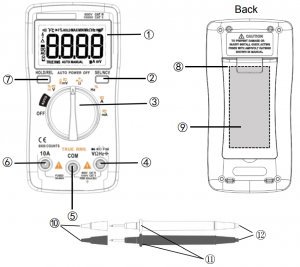
Appearance
- LCD Display
- SEL/NCV
- Function Dial
- Voltage/Diode/Resistance/ Continuity/Frequency/Temperature /Capacitance Input Terminal
- COM Terminal
- Current Input Terminal
- Data Hold/REL
- Stand
- Battery Cover
- Probe Cover
- Test Lead Insulator
- Test Leads
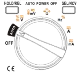
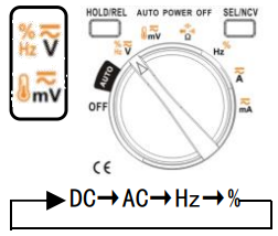
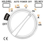
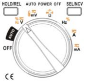
Function Dial
(a) Power (OFF)(b) AUTO (Voltage/Resistance/ Continuity) ![]() (c) Voltage/Frequency/ Duty Cycle
(c) Voltage/Frequency/ Duty Cycle ![]() (d) Temperature/mV Voltage(e) Diode/Resistance/Continuity/ Capacitance
(d) Temperature/mV Voltage(e) Diode/Resistance/Continuity/ Capacitance ![]() (f) Frequency/Duty Cycle
(f) Frequency/Duty Cycle ![]() (g) A Current(h) mA Current
(g) A Current(h) mA Current ![]()
Measurements
Steps for measurement
- Confirm the measurement content in the table on the right.
- Switch function dial according to the item to be measured.
- Please remove test leads after measuring.
- Turn off the power.
![]() Caution
Caution
- Do not confuse the item to be measured with the position of the function.
- Do not exceed the maximum rated value of each function.
- Do not switch functions or modes during measurement.
- During the measurement process, hold the insulated part of the test lead and do not hold the pins of the test lead.
Auto Power Off
- This feature prevents the battery from running out if you forget to turn off the power.
- If the operation is not continued for about 15 minutes, the auto power off function will automatically cut off the power.
- If you want to cancel this function, you should press and hold the SEL/NCV button and then turn it on again. It will be cancelled after five beeps.
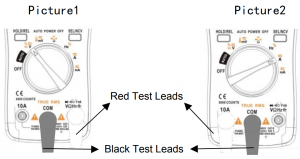
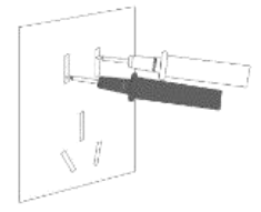
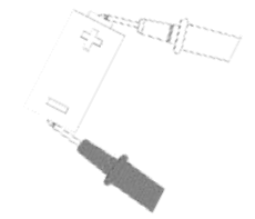
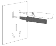
※ Methods of Connecting Test Leads
- Put the black lead into COM terminal and put the red lead to terminal in Picture1
- Put the red lead to 10A terminal when test the current in Picture2.
|
Measurement |
Function Position |
Data Display |
Connection Illustration | Usage and Notice |
|
Auto |
Auto-recognition for Voltage /Resistance/ Continuity by connecting test leads |
 |
 |
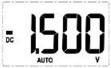
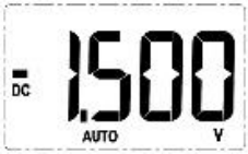
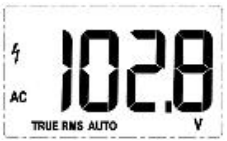
Please rotate dial to AUTO position; Put probes correctly to recognize Voltage/Resistance/Continuity automatically. Only when the voltage is higher than 0.8V, this data will be shown on the display.※ Voltage/Resistance/Continuity can be also measured by switch dial to function position manually. |
 |
||||
 |
||||
|
DC Voltage AC Voltage (Frequency Duty Cycle) Temperature |
Please select temperature function in mV by SEL/NCV |
 |
 |
|
 |
 |
|||
|
DC Current |
 |
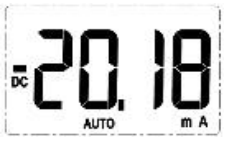 |
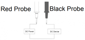 |
|
|
AC Current |
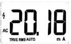 |
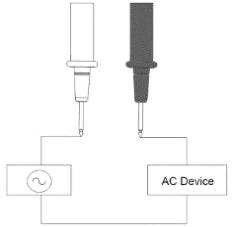 |
||
|
ResistanceΩ |
 |
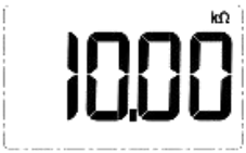 |
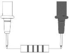 |
|
|
Continuity |
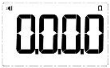 |
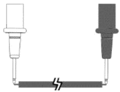 |
The built-in beeper will beep when the resistance is lower than 50Ω, which indicates a short circuit.※ Please measure the resistance range in order to get detailed resistance. | |
|
Diode |
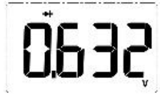 |
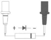 |
|
|
|
Capacitance |
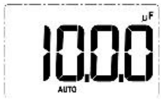 |
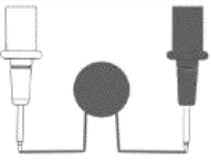 |
|
|
|
Frequency Duty Cycle Hz/% |
 |
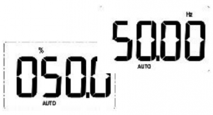 |
||
|
NCV Function |
 |
 |
||
|
Data Hold/REL HOLD/REL |
 |
 |
Maintenance
Replace Battery
When “ ![]() ” is shown on the display, batteries should be replaced as below:
” is shown on the display, batteries should be replaced as below:
- Remove the test leads and turn off the product before replacing the batteries;
- Loosen the screw on the battery door and remove the battery door.
- Replace the used batteries with new batteries of the same type.
- Place the battery door back and fasten the screws
Replace the Fuses
If current measurement is not possible, make sure that the fuse is not blown.If it is blown, please replace the required rated fuse.
- Remove the battery cover and battery according to the battery replacement method;
- Use a screwdriver to remove the two screws on the back cover.
- Remove the back cover;
- Replace the fuse;
- Put the back cover and battery cover back, tighten the screws.
Clean the Product
Wipe the product with a damp cloth and mild detergent.Do not use abrasives or solvents. Dirt or moisture in the terminals can affect readings.*Remove the input signals before you clean the product.
Calibration
Calibration is regularly performed at the calibration laboratory to ensure accurate measurements.The recommended calibration period is once a year.Please consult your dealer for calibration cost and delivery time
Storage Method
Please turn off the power after use to avoid consuming the built-in battery.If it is not used for a long time, please remove the battery and keep it.
True RMS Voltmeter User Manual – True RMS Voltmeter User Manual –
[xyz-ips snippet=”download-snippet”]