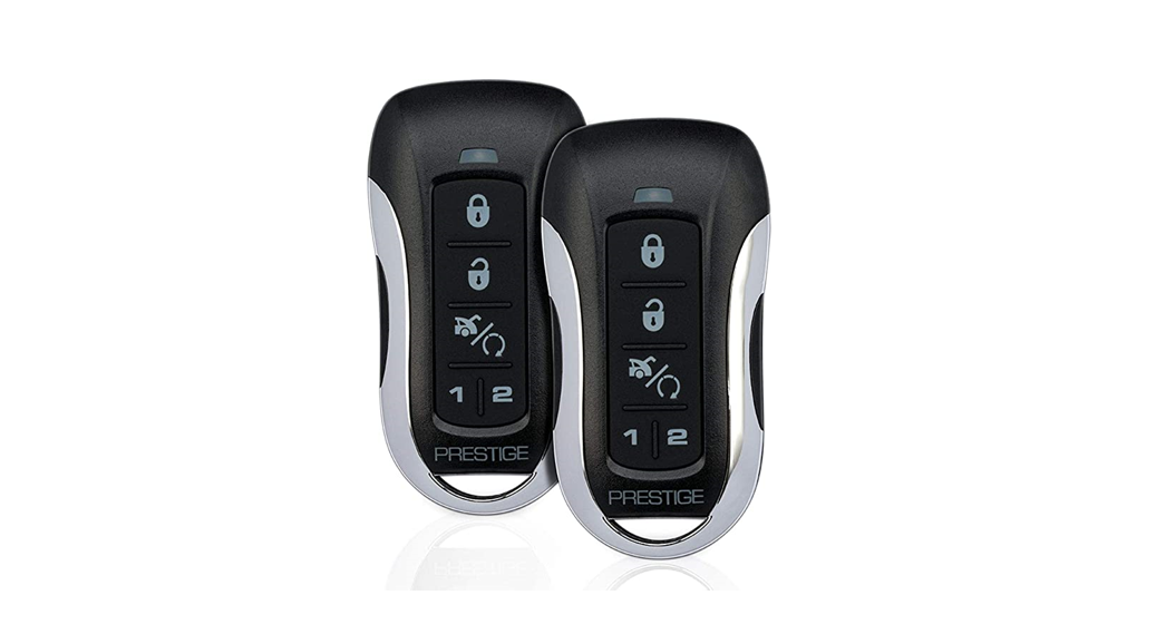
![]() APS787ZVehicle Security / Remote Start System
APS787ZVehicle Security / Remote Start System
Installation and Reference Guide Thank you for trusting Prestige products! If you are a consumer, please note:Professional installation is strongly recommended.This manual assumes the installer has adequate knowledge of the following expertise. Therefore, it does not cover these topics in detail:
- 12-volt electronics
- Testing and verifying circuits
- Making safe and lasting wiring connection
- Factory ignition, power, lighting, data bus, and sensing systems
- Factory systems and components to avoid
- Safe wire routing, circuit protection, and product placement
- Access to vehicle-specific technical information
In addition, this manual assumes the installer has the proper tools, skills,s, and facilities to perform a professional installation. Performing an improper installation could result in damage to the vehicle or its components, improper system function, unsafe vehicle operation, or physical injury. Such instances would not be covered by the vehicle manufacturer’s warranty, nor by Voxx Electronics, Inc.
Detailed Descriptions
Wire Harness Colors and Functions
Power Connector (8-pin High-Current Connector)
See page 33 for the full system diagram.These wires are listed in order of their placement in the harness connector.
- RED/BLACK – Ignition 3, Flex Relay Input (Internal Relay Pin 87)The RED/BLACK wire is used to supply the Pin 2 – PINK Flex Relay Output. This wire can be connected to 12-Volt (+) or Ground (-). Please check vehicle requirements for correct polarity.Note: Before making this connection, remove all module fuses until the system is completely connected.
- PINK – Ignition 3 Flex Relay Output (Internal Relay Pin 30)At its default setting, the PINK wire supplies 12-Volt (+) or Ground (-) to the vehicle’s secondary ignition wire during remote start. The polarity of this output is provided by the Pin 1, RED/BLACK Input.Verification: If present, the secondary ignition wire registers 12-Volt (+) or Ground (-) when the vehicle is in ignition mode AND during engine crank.Note: This wire can be programmed to perform a different function by changing its options. Refer to Bank 3, Feature 8 on page 13.
- YELLOW – Starter Output for Remote Start (+)The YELLOW wire supplies 12-Volt (+) to the vehicle’s starter wire when remote start is enabled and turns off once the vehicle is started.Verification: This starter wire registers 12-Volt (+) during engine crank.Note: If installing a starter kill relay in addition to remote start, connect the YELLOW wire to the MOTOR SIDE of the cut starter wire. Refer to the Start Kill diagram on page 32.
- GREEN – Ignition 2 Output (+)At its default setting, the GREEN wire supplies 12-Volt (+) to the vehicle’s secondary ignition wire during remote start. Verification: If present, the secondary ignition wire registers 12-Volt (+) when the vehicle is in ignition mode AND during engine crank.Note: This wire can be programmed to perform a different function by changing its options. Refer to Bank 3, Feature 7on page 13.
- RED – 12-Volt Input (+)The RED wire connects to the vehicle’s primary 12-Volt (+) wire to power the system.Verification: The power wire registers 12-Volt (+) at all times.Note: Before making this connection, remove all module fuses until the system is completely connected.
- RED/WHITE – 12-Volt Input (+)The RED/WHITE wire connects to the vehicle’s secondary 12-Volt (+) wire to power the remote start function.Verification: The power wire registers 12-Volt (+) at all times.Note: Before making this connection, remove all module fuses until the system is completely connected.
- PURPLE – Accessory Output (+)At its default setting, the Purple wire supplies 12-Volt (+) to the vehicle’s accessory wire to power vehicle accessories during remote start.Verification: The accessory wire registers 12-Volt (+) when the vehicle is running or in accessory mode, but not during engine crank or if the vehicle is off.Note: This wire can be programmed to perform a different function by changing its options. Refer to Bank 3, Feature 9on page 13.
- BLUE – Ignition 1 Input / Output (+)The BLUE wire supplies 12-Volt (+) to the vehicle’s primary ignition wire during remote start. This wire is also used to sense vehicle ignition for the Programming Functions Verification: The primary ignition wire registers 12-Volt (+) when the vehicle is in ignition mode AND during engine crank.
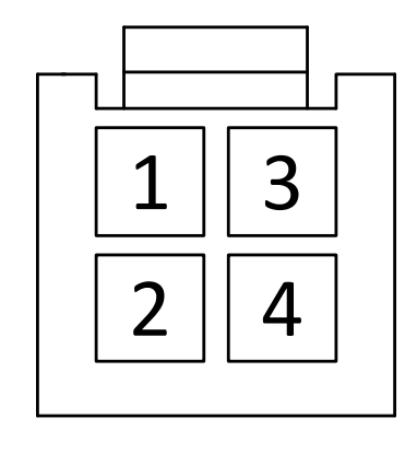
Alarm / Notification Connector (4-pin connector) See page 33 for the full system diagram.
These wires are listed in order of their placement in the harness connector.
- WHITE – Parking Light Relay Output (Internal Relay Pin 30)At its default setting, the WHITE wire supplies 12-Volt (+) or Ground (-) to the vehicle’s park light wire based on the connection of the relay input (WHITE/RED wire).Verification: The vehicle parking light wire registers 12-Volt (+) or Ground (-) when the park lights are turned on. Note: This wire can be programmed to perform the Trunk Release Output function by changing its options. Refer to Bank 2, Feature 14 on page 9.
- WHITE/RED – Parking Light Relay Input (Internal Relay Pin 87)The WHITE/RED connects to vehicle 12-Volt (+) or Ground (-) to supply the relay output (WHITE wire).Verification for default setting:• If the vehicle parking light wire registers 12-Volt (+) when the park lights are on, connect the WHITE/RED wire to a constant 12-Volt (+) vehicle wire.• If the vehicle parking light wire registers Ground (-) when the park lights are on, connect the WHITE/RED wire to a reliable vehicle groundNote: This wire can be programmed to perform the Trunk Release Output function by changing its options. Refer to Bank 2, Feature 14 on page 9.
- WHITE/BLACK – Siren Output (+)The WHITE/BLACK wire supplies 12-Volt (+) to power the siren. After mounting the siren, connect its BLACK wire to a reliable ground source, and connect the WHITE/BLACK wire to the siren’s RED wire.
- BLACK – Ground Input (-)The BLACK wire connects to a reliable vehicle ground (-) source to power the system.Verification: The vehicle ground (-) source wire registers ground (-) at all times.Note: Before making this connection, remove all module fuses until the system is completely connected.
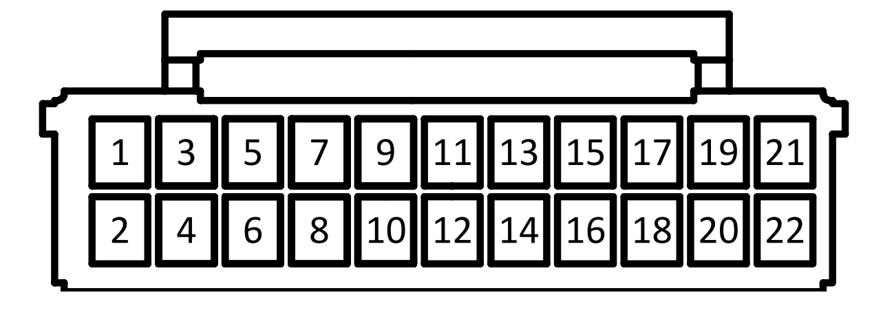
Input / Output Connector (22-pin connector) See page 33 for the full system diagram.
These wires are listed in order of their placement in the harness connector.
- ORANGE – Starter Kill Output (-)The ORANGE wire supplies Ground (-) when the alarm is armed and when the remote start is ON.
- LIGHT GREEN – Trunk / Hatch Input (-) (PIC1)The LIGHT GREEN wire connects a device or switch that, when triggered, supplies a Ground (-) output. If the system is armed, this input will trigger the alarm.Note: This wire is programmable. Refer to PIC Programming on page 20.
- GRAY/BLACK – Hood Input (-) (PIC2)The GRAY/BLACK wire connects to the vehicle’s hood switch or an installed switch that registers Ground (-) when triggered.Note: This wire is programmable. Refer to PIC Programming on page 20.Verification: The vehicle hood switch wire registers Ground (-) when the hood is opened.
- GREEN/ORANGE – Tach InputThe GREEN/ORANGE wire connects to the vehicle’s tach wire at the negative side of the ignition coil or fuel injector to control the engine crank during remote start.Verification:• Using a voltmeter set to AC volts, connect the voltmeter’s positive lead to a constant vehicle 12-Volts (+) source and the negative lead to the wire to be• Start the engine and have a partner slowly press the gas pedal while the transmission is in If the voltage increases as the RPM increases, this is the proper tach wire.
- LIGHT BLUE – Remote Start Status Output (-) (NOC 1)The LIGHT BLUE wire supplies Ground (-) as soon as the remote starter is activated and remains active until (4) seconds after remote start run time has ended. This wire is most commonly used to activate data integration modules.Note: This wire is programmable. Refer to NOC Programming on page 11.
- PURPLE/BROWN – Door Trigger Input (-/+)The PURPLE/BROWN wire connects to the vehicle’s door trigger wire. This wire will detect 12-Volt (+) or Ground (-) input. Verification: The vehicle door trigger wire registers 12-Volt (+) or Ground (-) when a door is opened and opposite when closed.Note: Programming is required if the door trigger wire registers 12-Volt (+). Refer to Feature Programming on page 9.
- GREEN/WHITE – Dome Light Output (-) (NOC 2)The GREEN/WHITE wire supplies Ground (-) when Unlock is activated from the Remote Control. This output will automatically turn off after 30 seconds.Note: This wire is programmable. Refer to NOC Programming on page 17.
- GREEN/YELLOW – Diesel Glow Plug Input (+) (PIC3)The GREEN/YELLOW wire connect to the vehicle’s Diesel Glow Plug detection wire.Verification: This wire will register as 12-Volt (+) while the Diesel Wait to Start Light is illuminated.Note: This wire is programmable. Refer to PIC Programming on page 20.
- BLACK/YELLOW – Pulse During Crank Output (-) (NOC 3)At its default setting, the BLACK/YELLOW wire supplies a Ground (-) pulse when the engine cranks during remote start.Note: This wire is programmable. Refer to NOC Programming on page 17.
- ORANGE/BLACK — Parking Brake Input (-) (PIC4)The ORANGE/BLACK wire connects to the vehicle’s parking brake wire to supply parking brake status for remote start. Verification: The vehicle parking brake wire registers Ground (-) once the parking brake is engaged.Note: This connection is only applicable to vehicles with a manual transmission, or if the turbo timer setting is active ‘System Programming: Bank 3. Features 10 & 16 on page 13).Note: This wire is programmable. Refer to PIC Programming on page 20.
- BLACK/RED — Pulse After Shutdown Output (-) (NOC 4)At its default setting, the BLACK/RED wire supplies a Ground (-) pulse when the remote start system is shut down. It is typically used to re-lock vehicle doors after remote start shutdown, or pulse the vehicle’s door trigger to turn off accessories after vehicle shutdown.Note: This wire is programmable. Refer to NOC Programming on page 17.
- DARK BLUE/BLACK — External Start Input (-) (PICS)The DARK BLUE wire connects to a device or switch that, when triggered, supplies a Ground (-) output. If the vehicle ignition is off, this input will activate the remote start function.Note: This wire is programmable. Refer to PIC Programming on page 20.
- BLACK/BLUE — Factory Disarm Output (-) (NOC 5)The BLACK/BLUE wire supplies a Ground (-) pulse when the system is disarmed and when remote start is activated. Verification: In most vehicles, the vehicle factory disarms wire registers Ground (-) if the driver door key cylinder is turned to the unlock position.Note: This wire is programmable. Refer to NOC Programming on page 17.
- BROWN/BLACK — Brake Input (+) (PIC6)The BROWN/BLACK wire connects to the vehicle’s brake wire to supply brake status for remote start.Verification: The vehicle brake wire registers 12-Volts (+) when the brake is activated. Note: This wire is programmable. Refer to PIC Programming on page 20.
- BLACK/LIGHT GREEN — Factory Arm Output (-) (NOC 6)At its default setting, the BLACK/LIGHT GREEN wire supplies a Ground (-) pulse when the system is armed and when the vehicle has been successfully started using remote start. It is typically used to re-lock vehicle doors after remote start if necessary.Note: This wire is programmable. Refer to NOC Programming on page 17.
- RED/BLACK — 2nd Unlock Output (-) (NOC 12)At its default setting, the RED/BLACK wire supplies a Ground (-) pulse when the Unlock button is pressed 2x within 10 seconds. This requires Feature Bank 2, Feature 10, to be programmed ON. Additional Ports may be required.Note: This wire is programmable. Refer to NOC Programming on page 17.
- LIGHT BLUE/GREEN — Ch. 5 Aux. Output (-) (NOC 7)The LIGHT BLUE/GREEN wire supplies Ground (-) when activated from the remote control.Note: This wire is programmable. Refer to NOC Programming on page 17.
- BLACK/WHITE — Horn Output (-)The BLACK/WHITE wire connects to the vehicle’s horn wire and supplies Ground (-) when activated from the system. Verification: The vehicle horn wire registers Ground (-) when the horn is activated.
- GREEN/LIGHT BLUE — Ch. 4 Aux. Output (-) (NOC 8)The GREEN/LIGHT BLUE wire supplies Ground (-) when activated from the remote control.Note: This wire is programmable. Refer to NOC Programming on page 17.
- RED — Door Lock (-) (NOC 10)The RED wire supplies Ground (-) when the Lock function is activated from the remote control or system.Verification: The vehicle lock wire registers 12-Volts (+) or Ground (-) when the Lock button is activated. Additional parts may be required. See Page 29 for common door lock wire diagrams.Note: This wire is programmable. Refer to NOC Programming on page 17.
- DARK BLUE — Trunk Release Output (-) (NOC 9)At its default setting, the DARK BLUE wire connects to the vehicle trunk release wire or relay and supplies Ground (-) when activated from the remote control.Verification: The vehicle trunk release wire registers 12-Volt (+) or Ground (-) when the trunk release button is activated.Note: This wire can be programmed to perform the Parking Lights Output function by changing its options. Refer to Bank 2. Feature 14 on page 9 and NOC Programming on page 17.
- GREEN — Door Unlock (-) (NOC 11)The GREEN wire supplies Ground (-) when the Unlock function is activated from the remote control or system. Verification: The vehicle lock wire registers 12-Volt (+) or Ground (-) when the Unlock button is activated. Additional parts may be required. See Page 29 for common door lock wire diagrams.Note: This wire is programmable. Refer to NOC Programming on page 17.
External Components
Shock Sensor
The shock sensor plugs into a 4-pin connector on the Prestige module. It should be securely attached to a vehicle surface or sturdy wire harness. Testing takes place alter all connections are made and the system is powered up. Refer to Quick Reference: System Diagnostics on page 26 for instructions on testing and adjusting the shock sensor.
RF Antenna / LED / Programming Port
The long-range antenna kit plugs into a 4-pin connector on the Prestige module.
- Mount the supplied antenna/receiver to a clear spot on the vehicle’s windshield that will not block the driver’s vision. A suitable location is high on the windshield near the rear-view mirror.
- Be careful not to mount the antenna/receiver on any metallic window film, as this will affect the system range.
- Route the antenna/receiver cable to the Prestige module, ensuring it does not block or interfere with the deployment of the airbag (if equipped.) Plug into the antenna port.
Data Bus Interface (DBI) Port
The 4-pin Data Bus Interface enables a FlashLogic door lock or transponder Interface to connect to and communicate with the vehicle data bus. The combined system saves installation time as many features that normally require individual connection can be accessed and controlled through the data bus. Please refer to the D2D (Data to Data) function list available per vehicle at www.Flashlogic.com.FLCART Cartridge PortThis port is for installing the FlashLogic FLCART data immobilizer & door lock interface cartridge used to communicate with the vehicle’s data bus.Weblink Programming PortThis 4-pin port is used for programming the FlashLogic FLCART interface cartridge via the FLPROG Weblink or Weblink Mobile. Refer to the FlashLogic website for more details.IFLCART Harness PortThis port is for the harness included with the FLCART interface cartridge. Refer to the FlashLogic website for more details.
Telematics Interface Port
The 4-pin Telematics port enables a connected interface such as CarLink to expand system control to a smartphone or tablet. The following features may be able to be activated from a connected device:
- Door Lock Control
- Remote Start
- Trunk Release
- Auxiliary Output
- Sliding Doors
Setup Options
Bank 1: Add / Remove Remote Controls
Remote programming is located in Feature Bank 1. This system will Auto Program basic functions of the remote with one (1) button press. Basic functions are channels 1-3, Lock, Unlock, and Trunk / Start.
|
Feature Bank 1 |
Description |
||
| Channel | 1 | Auto Program/lock | The press lock button on remote |
| 2 | Unlock | Press Unlock button on remote | |
| 3 | Trunk/Start | Press the Trunk/Start button on remote | |
| 4 | Ch. 4 AUX | Press button/buttons to control AUX Ch. 4 | |
| 5 | Ch. 5 AUX | Press button/buttons to control AUX Ch. 5 | |
| 6 | Ch. 6 AUX | Press button/buttons to control AUX Ch. 6 | |
| 7 | Ch. 7 AUX | Press button/buttons to control AUX Ch. 7 |
To Auto Program a remote control:
- Turn the ignition key to ON.
- Press and release the valet/override button three (3) times.
- The system will beep one (1) time, indicating you have accessed Bank 1, Remote Programming.
- Press the Lock button of each remote control you wish to program. (Channels 1-3 of the remote control will be ) The system will beep one (1) time when each remote control is added.
- Turn the ignition key to OFF to exit programming mode, or cycle the ignition key OFF/ON to advance to the next Feature Bank.
To delete a remote control:This system will store a maximum of four (4) remote controls in the memory. Additional programmed remote controls will delete the oldest programmed remote control.Deleting All Remotes:
- Perform steps 1-3 above.
- Press and hold the Valet button for five (5) seconds.
- The system will sound one (1) long beep. This indicates all remotes have been deleted from memory.
Notes:
- The system will store in the memory a maximum of four (4) remote controls. Additional programmed remote controls will delete the oldest programmed remote control.
- The system will accept a maximum of two (2) 2-Way remote controls.
- During normal operation, the Programmed Transmitter Notification (PTN) function indicates how many remote controls are programmed by flashing the LED a certain number of times when the vehicle ignition is turned on.
AUX Output Controls.AUX Output Controls are not configured during the Auto Programming sequence. This allows for customization by the installer or user. To program AUX Output Control:
- Repeat steps 1-3 above.
- Press the valet button to advance to the AUX Channel to be programmed. The system will beep to indicate the channel number.
- Press the desired button or button combination selected to control the AUX output. The system will beep one (1) time to indicated the channel is programmed.
Repeat steps 2-3 until all desired AUX outputs are programmed or turn the ignition key OFF to exit programming
Security Control (Bank 2)
See page 23 for Programming Instruction.
|
Feature Bank 2 |
Options | |||||||
| 1Chirp | 2Chirp | 3Chirp | 4Chirp | 5Chirp |
6Chirp |
|||
|
Features |
1 | Lock / Unlock Function | 500ms | 3.5sec | 500ms L, DBL UL | DBL L, 500ms UL | DBL L, DBL UL | 500ms L, 350ms UL |
| 2 | Ignition Lock | OFF | ON | |||||
| 3 | Ignition Unlock | OFF | Unlock All | Unlock Driver | ||||
| 4 | Exterior Illumination | OFF | With Arm | With Disarm | With Arm & Disarm | |||
| 5 | Auto Relock | OFF | Auto-Lock Only | Auto-Lock & Arm | ||||
| 6 | Auto Arming / Locking | OFF | Auto Arm Only | Auto-Lock & Arm | ||||
| 7 | Notification Sound | Both | Siren | Horn | ||||
| 8 | Horn Timing | 16ms | 30ms | 40ms | 50ms | 10ms | ||
| 9 | Valet Override Method | Valet | Custom Code | Stand Alone Valet | ||||
| 10 | Driver Priority Unlock | OFF | ON | |||||
| 11 | Silent Choice | OFF | From Transmitter | OEM Style | ||||
| 12 | Security Profile | All On | Doors off | Hood/trunk Off | All Off | All On w/ OEM RS | ||
| 13 | Door Trigger Input | Negative | Positive | |||||
| 14 | Park Light / Trunk Swap | OFF | ON | |||||
| 15 | Data Port Protocol | ADS | DBI | |||||
| 16 | Dome Light Delay Timer | OFF / Program | 15sec | 30sec | 45sec | 60sec | 120sec | |
| 17 | Alarm Trigger Length | 30sec | 45sec | 60sec | 90sec | 120sec |
Feature 1: Lock / Unlock FunctionFunction: Set the lock / unlock output timing and functionality for specific vehicle lock types.Setting Choices:
- Option 1 – Lock and Unlock outputs will pulse for 500
- Option 2 – Lock and Unlock outputs will pulse for 5 seconds.
- Option 3 – Lock output will pulse for 500ms; Unlock output will pulse twice, 500ms
- Option 4 – Lock output will pulse twice, 500ms each; Unlock output will pulse for 500ms.
- Option 5 – Lock and Unlock outputs will pulse twice for 500ms.
-
Option 6 – Lock output will pulse for 500ms; Unlock output will pulse for 350ms.
Feature 2: Ignition-Activated LockFunction: Set the door locks to lock when the brake is pressed after the ignition is turned ON.Setting Choices:
- Option 1 – Doors do not lock with
- Option 2 – Doors Lock when the brake is pressed after ignition on.
Feature 3: Ignition-Activated UnlockFunction: Set the door locks to unlock when the ignition is turned off with the key.Setting Choices:
- Option 1 – Doors do not unlock with ignition off.
- Option 2 – All Doors Unlock with ignition
- Option 3 – Driver Door Unlocks with ignition off.
Feature 4: Exterior IlluminationFunction: Set the parking lights and headlights to remain on for 30 seconds when the doors are locked or unlocked with the remote control.Setting Choices:
- Option 1 – The lights will function
- Option 2 – The lights will remain on for 30 seconds when the doors are locked with the remote
- Option 3 – The lights will remain on for 30 seconds when the doors are unlocked with the remote
- Option 4 – The lights will remain on for 30 seconds when the doors are locked or unlocked with the remote
Feature 5: Auto ReLock SettingFunction: Set the doors to re-lock if the system has been accidentally disarmed.Setting Choices:
- Option 1 – Auto ReLock is disabled.
- Option 2 – If the system has been disarmed but no doors have been opened in 3 minutes, the system will relock the doors but not re-arm the alarm.
- Option 3 – If the system has been disarmed but no doors have been opened in 3 minutes, the system will relock the doors and re-arm the alarm.
Note: This feature is not associated with Auto Arming / Locking.Feature 6: Automatic ArmingFunction: Set the system to arm automatically after exiting the vehicle.Setting Choices:
- Option 1 – The system will arm and doors will lock only when the alarm is armed from the remote control.
- Option 2 – The system will arm automatically 1 minute after the last door is closed, and when the alarm is armed from the remote control.
- Option 3 – The system will Arm and Lock doors automatically 1 minute after the last door is closed, and when the alarm is armed from the remote control.
Feature 7: Notification SoundsFunction: Set the siren and/or horn to notify when the system is armed or disarmed.Setting Choices:
- Option 1 – Siren and horn will emit audible beeps when the system is armed and
- Option 2 – Siren will emit audible beeps when the system is armed and
- Option 3 – Horn will emit audible beeps when the system is armed and disarmed.Note: Siren and horn will both sound if the system is triggered, regardless of this
Feature 8: Horn Output DurationFunction: Set the horn output to activate for a set time.Setting Choices:
- Option 1 – Output pulses for 16 milliseconds.
- Option 2 – Output pulses for 30 milliseconds.
- Option 3 – Output pulses for 40 milliseconds.
- Option 4 – Output pulses for 50 milliseconds.
- Option 5 – Output pulses for 10 milliseconds.
Feature 9: Valet Override MethodFunction: Set the Alarm Override Method. This will be used if the Remote is lost or inoperable.Setting Choices:
- Option 1 – Alarm Override method is Ignition Key ON, press Valet button one (1) time.
- Option 2 – The alarm Override method is set for a Custom Code.
- Option 3 – The alarm Override method is set for Stand-Alone Valet Mode.
Note: See Alarm Override and Custom Code Programming procedures on page 28.Feature 10: Driver Priority UnlockFunction: Set the behavior of unlocking outputs when arming and disarming the system.Setting Choices:
- Option 1 – Unlock pulse will be on the Green wire unlock output only.
- Option 2 – First press of unlocking on remote will pulse Green wire; Second press within 10sec will pulse RED/BLACK wire.
Feature 11: Silent ChoiceTMFunction: Set audible beeps on or off when arming and disarming the system.Setting Choices:
- Option 1 – Pressing Lock or Unlock at any time will perform the function with audible
- Option 2 – Pressing Lock or Unlock for 5sec on remote will control system without an audible beep.
- Option 3 – First press of Lock or Unlock on the remote control will perform the function without an audible beep. Second press within 10sec will result in audible beeps.
Feature 12: Security ProfileFunction: Set the system to function as a keyless entry/convenience system or full-featured alarm/convenience system.Setting Choices:
- Option 1 – All security, keyless entry, and convenience features are enabled.
- Option 2 – The door Trigger zone is disabled.
- Option 3 – Hood and Trunk Trigger zones are
- Option 4 – All security trigger zones are
- Option 5 – All security zones are enabled: Doors, Hood, and Trunk will be bypassed for five (5) seconds with Ignition ON; Shock will be bypassed anytime Ignition is ON.
Feature 13: Door Trigger Input DetectionFunction: Set the system to detect 12-Volt (+) or Ground (-) when the vehicle door is opened.Setting Choices:
- Option 1 – Door Trigger detection is set for Ground (-).
- Option 2 – Door Trigger detection is set for 12-Volt (+).
Feature 14: Park Light / Trunk Relay FunctionFunction: Reverse the functionality of the trunk and park light outputs (i.e. when the built-in relay is needed for the trunk connection but not needed for the park light connection).Setting Choices:
- Option 1 – Functionality follows default settings.
- Option 2 – The Trunk Release Output (Dark Blue) wire works with the Parking Lights function; the Parking Lights Input (White/Red) and Parking Lights Output (White) wires work with the trunk release
Feature 15: Data Bus (DBI) Port ProtocolFunction: Set functionality of the data bus connector to accept integration modules of differing protocols.Setting Choices:
- Option 1 – The data bus connector will be configured to work with modules that use the ADS
- Option 2 – The data bus connector will be configured to work with modules that use the DBI
Feature 16: Dome Light Delay TimerFunction: Set the delay timer when using the vehicle’s Dome Light as a door trigger.Setting Choices:
- Option 1 – OFF / Delay Timer will be OFF or use the programmed See page 25 for dome light delay programming procedure
- Option 2 – 15 seconds, System will wait 15 seconds before monitoring the door trigger
- Option 3 – 30 seconds, System will wait 30 seconds before monitoring the door trigger
- Option 4 – 45 seconds, System will wait 45 seconds before monitoring the door trigger
- Option 5 – 60 seconds, System will wait 60 seconds before monitoring the door trigger
- Option 6 – 120 seconds, System will wait 120 seconds before monitoring the door trigger
Feature 17: Alarm Trigger LengthFunction: Set the length of time the Alarm Notification will sound for each cycle. Setting Choices:
- Option 1 – 30 seconds, System will Alarm Cycle will sound for 30
- Option 2 – 45 seconds, System will Alarm Cycle will sound for 45
- Option 3 – 60 seconds, System will Alarm Cycle will sound for 60
- Option 4 – 90 seconds, System will Alarm Cycle will sound for 90
- Option 5 – 120 seconds, System will Alarm Cycle will sound for 120
Note: The system will check the trigger inputs between each Alarm Cycle. If the trigger input is still active the system will notify the user with another cycle.
Remote Start Control (Bank 3)
See page 23 for Programming Instruction.
| Feature Bank 3 | Options | ||||||
| 1 Chirp | 2 Chirp | 3 Chirp | 4 chirp | 5 Chirp | 6 Chirp | ||
| Features | 1 | Defrost Output | Pulsed | 10min | RS Runtime | ||
| 2 | RS Start Notification | ON | OFF | ||||
| 3 | RS Runtime | 15min | 20min | 45min | 60min | 5min | 10min |
| 4 | RS Parking Lights | Steady | Flashing | ||||
| 5 | Engine Confirmation | Tach | Voltage | Data | Hybrid | ||
| 6 | Voltage Level | >0.5v 84 Start | <0.5v B4 Start | ||||
| 7 | Ignition 2 Output | Ignition | Accessory | Start | |||
| 8 | Ignition 3 Output | Ignition | Accessory | Start | |||
| 9 | Accessory Output | Accessory | Ignition | Start | |||
| 10 | Transmission | Auto | Manual | ||||
| 11 | Max Crank Time | 0.8sec | 1.0sec | 1.5sec | 2.0sec | 3.0sec | 4.0sec |
| 12 | Diesel Delay | OFF | Diesel 5 | Diesel 10 | Diesel 15 | Diesel 20 | Diesel 30 |
| 13 | Temperature Start | OFF | 14F | 5F | OF | -4F | -14F |
| 14 | Crank Duration | Averaging | Preset | ||||
| 15 | RS Shock Override | Shunt until Clear | Shunt RS Cycle | Shunt From TX | |||
| 16 | Turbo Timer | OFF | 3min | 5min | 10min | ||
| 17 | Start Activation | Two Press | One-Press | Three Press | |||
| 18 | RS Lock Function | No Change | UL Before L After | UL Before Start | Lock After Start | ||
| 19 | Factory Disarm Output | Single Pulse | Double Pulse | 350ms | 500ms | 800ms | Same As Bank 2, Fl |
| 20 | Additional Unlock Pulse | No Pulse | IGN, ACC, GWR | IGN,ACC,GWR,PASD |
Feature 1: Defrost Output DurationFunction: Set the Defrost output to activate for a set time.Setting Choices:
- Option 1 – Output pulses for 1 second.
- Option 2 – Output stays on for 10
- Option 3 – Output stays on for the duration of the Remote Start Runtime.
Feature 2: Remote Start NotificationFunction: Set remote start activation confirmation beeps on or off.Setting Choices:
- Option 1 – On – System emits an audible beep when remote start is
- Option 2 – OFF -System remains silent when remote start is
Feature 3: Remote Start Run TimeFunction: Set the maximum remote start run time if the vehicle is not entered after activation.Setting Choices:
- Option 1 – The engine will run for 15 minutes.
- Option 2 – The engine will run for 20 minutes.
- Option 3 – The engine will run for 45 minutes.
- Option 4 – The engine will run for 60 minutes.
- Option 5 – The engine will run for 5 minutes.
- Option 6 – The engine will run for 10 minutes.
Feature 4: Remote Start Parking Light Duration|Function: Set parking light output to turn on or flashlights during remote start.Setting Choices:
- Option 1 – Lights remain on during remote start.
- Option 2 – Lights flash during remote start.
Feature 5: Engine Confirmation ModeFunction: Determine how the system knows if the remote start was successful. Setting Choices:
- Option 1 – Determined by measurement from the Purple/White Tach Input
- Option 2 – Determined by the voltage difference before the remote start and after asset in Bank 3, Feature 6.
- Option 3 – Receives information through an attached data bus interface.
- Option 4 – No sense; assumes vehicle has started based on the setting in Bank 3, Features 11 & 14.
Feature 6: Start Sensing Voltage LevelFunction: Set the sensitivity of voltage variance measurement to determine if the vehicle has started when Feature 5 is set to option 2, Voltage.Setting Choices:
- Option 1 – High: Voltage difference before the remote start and after must be greater than .5
- Option 2 – Low: Voltage difference before the remote start and after must be less than .5
Feature 7: Ignition 2 Output Function (Green)Function: Set the functionality of the programmable Ignition 2 output.Setting Choices:
- Option 1 – Wire sends 12-Volt (+) during ignition and
- Option 2 – Wire sends 12-Volt (+) during ignition; drops out during start.
- Option 3 – Wire sends 12-Volt (+) during start only.
Feature 8: Ignition 3 Output Function (Pink)Function: Set the functionality of the programmable Ignition 3 output.Setting Choices:
- Option 1 – Wire sends 12-Volt (+) during ignition and
- Option 2 – Wire sends 12-Volt (+) during ignition; drops out during start.
- Option 3 – Wire sends 12-Volt (+) during start only.
Feature 9: Accessory Output Function (Purple)Function: Set the functionality of the programmable Accessory output.Setting Choices:
- Option 1 – Wire sends 12-Volt (+) during ignition; drops out during
- Option 2 – Wire sends 12-Volt (+) during ignition and
- Option 3 – Wire sends 12-Volt (+) during the start
Feature 10: Transmission TypeFunction: Set the functionality of the remote start system based on the vehicle transmission type.Setting Choices:
- Option 1 – System is set for Automatic
- Option 2 – System is set for Manual (Note: Remote Start Ready Mode must be set by the driver before exiting the vehicle.)
Feature 11: Maximum Crank TimeFunction: Set maximum crank time for all remote start settings.Setting Choices:
- Option 1 – Starter will crank for .8 second
- Option 2 – Starter will crank for 1 second.
- Option 3 – Starter will crank for 5 seconds.
- Option 4 – Starter will crank for 2 seconds.
- Option 5 – Starter will crank for 4 seconds.
Feature 12: Diesel (Pre-Start) DelayFunction: After remote start ignition is activated, set the delay of the crank to accommodate diesel engines.Setting Choices:
- Option 1 – Vehicle starts immediately after remote start
- Option 2 – Start is delayed for 5 seconds after remote start
- Option 3 – Start is delayed for 10 seconds after remote start
- Option 4 – Start is delayed for 15 seconds after remote start
- Option 5 – Start is delayed for 20 seconds after remote start
- Option 6 – Start is delayed for 30 seconds after remote start
Feature 13: Temperature-Based Start SettingFunction: Set the outside temperature that will automatically trigger the start function.Setting Choices:
- Option 1 – Temperature-based start is inactive.
- Option 2 – The vehicle will start when the temperature drops below 14 ° F.
- Option 3 – The vehicle will start when the temperature drops below 5 ° F.
- Option 4 – The vehicle will start when the temperature drops below 0 ° F.
- Option 5 – The vehicle will start when the temperature drops below -4 ° F.
- Option 6 – The vehicle will start when the temperature drops below -14 ° F.
Note: Requires Activation withFeature 14: Crank DurationFunction: Set how the system will determine how long to crank the starter.Setting Choices:
- Option 1 – Starter will crank based on the average of the last 8 times the vehicle was started with the
- Option 2 – Starter will crank for maximum time as set in Bank 3, Feature 11.
Feature 15: Remote Start Shock Sensor OverrideFunction: Set Shock Sensor Operation with Remote Start.Setting Choices:
- Option 1 – Shock Sensor will turn off when remote start is engaged and will turn on if no vibration is detected after the engine is
- Option 2 – Shock senor will turn off for the duration of the Remote Start
- Option 3 – Shock sensor will turn off if Lock is pressed while the vehicle is remote
Feature 16: Turbo Timer SettingFunction: Set the time that the engine remains running after the vehicle is turned off with the key.Setting Choices:
- Option 1 – Turbo timer function is inactive.
- Option 2 – The vehicle will remain running for 3 minutes.
- Option 3 – The vehicle will remain running for 5 minutes.
- Option 4 – The vehicle will remain running for 10 minutes.
Feature 17: Remote Start ActivationFunction: Set remote start to activate with one, two, or three presses from the remote control or pulses detected on the Dark Blue/Black External Activation Input.Setting Choices:
- Option 1 – Press the Start button two (2) times for remote
- Option 2 – Press the Start button one (1) time for remote
- Option 2 – Press the Start button three (3) times for remote
Note: This does not apply to 1 Button Transmitters.Feature 18: Remote Start Lock ControlFunction: If desired, set door lock outputs to function before or after the remote start.Setting Choices:
- Option 1 – Remote Start Lock Control is inactive.
- Option 2 – Doors will unlock before the remote start; lock after the remote start.
- Option 3 – Doors will unlock before the remote starts.
- Option 4 – Doors will lock after the remote starts.
Feature 19: Factory Disarm Output Function (BLACK/BLUE)Function: Set the functionality of the programmable output.Setting Choices:
- Option 1 – Sends a 1-second pulse before the start and during
- Option 2 – Sends a 350ms pulse before the start and during
- Option 3 – Sends a 500ms pulse before the start and during
- Option 4 – Sends an 800ms pulse before the start and during
- Option 5 – Sends a pulse before the start and during unlocking based on the setting of Bank 2, Feature 1.
Feature 20: Additional Unlock PulsesFunction: Set other outputs to pulse when the vehicle is unlocked with the remote control.Setting Choices:
- Option 1 – No additional unlock
- Option 2 – Pulse Ignition, Accessory, and Ground While Running wires upon
- Option 3 – Pulse Ignition, Accessory, Ground While Running, and Pulse After Shutdown wires upon
Negative Output Control (NOC)
| Lock | Ground While Armed |
| Unlock | Ground While Disarmed |
| 2nd Unlock | Domelight |
| Trunk | Headlight |
| Remote Start Status | Defrost |
| Ignition | LED |
| Accessory | Ch. 4 AUX |
| Pulse During Crank | Ch. 5 AUX |
| Pulse After Shutdown | Ch. 6 AUX |
| Factory Arm | Ch. 7 AUX |
| Factory Disarm |
Auxiliary Output Control (AUX Control)
| 1 Second Pulse | 30 Second Pulse |
| 5 Second Pulse | Push & Hold |
| 10 Second Pulse | Latch ON/OFF |
| 15 Second Pulse | Latch 10min |
| 20 Second Pulse | Latch Runtime |
1 Second PulseThis option supplies a one (1) second pulse each time the AUX Ch. is activated from the remote or CarLink System.5 Second PulseThis option supplies a five (5) second pulse each time the AUX Ch. is activated from the remote or CarLink System.10 Second PulseThis option supplies a ten (10) second pulse each time the AUX Ch. is activated from the remote or CarLink System.15 Second PulseThis option supplies a fifteen (15) second pulse each time the AUX Ch. is activated from the remote or CarLink System.20 Second PulseThis option supplies a twenty (20) second pulse each time the AUX Ch. is activated from the remote or CarLink System.30 Second PulseThis option supplies a thirty (30) second pulse each time the AUX Ch. is activated from the remote or CarLink System.Push & HoldThis option will supply an output when the remote button is pressed by the user and will remain on until the user releases the remote button.Latch ON/OFFThis option will supply an output when the AUX Channel is activated from the remote control or CarLink system and remain on until the AUX Channel is activated again.Latch 10minThis option will supply an output when the AUX Channel is activated from the remote control or CarLink system and remain on for ten (10) minutes.Runtime LatchThis option will supply an output when the remote start is activated and remain on for the runtime selected on Feature Bank 3, Feature 3.
Programmable Input Control (PIC Control)
Programmable Input Control (PIC) allows each PIC input to be customized to the user or vehicle’s need. See the list below for a detailed description of the available options. PIC Inputs can only be programmed using the FlashLogic Weblink or Weblink Mobile.
| Door Trigger | Full Shock Trigger |
| Trunk Trigger | Parking Brake |
| Hood Trigger | Brake |
| N.C. Door Trigger | External Start Activation |
| Pre-Warn Shock Trigger | Diesel Glow Plug |
Door Trigger InputThis option will be used for all Door trigger functions including Alarm Trigger. If using an LCD RF kit this input will display the Door icon when the Alarm is triggered.Trunk Trigger InputThis option will be used for all Trunk trigger functions including the Alarm trigger. If using an LCD RF kit this input will display the Trunk icon when the Alarm is triggered.Hood Trigger InputThis option will be used for all Hood trigger functions including the Alarm trigger. If using an LCD RF kit this input will display the Hood icon when the Alarm is triggered.Normally Closed Door Trigger InputThis option will be used in vehicles with a Normally Closed Door Trigger. This type of circuit will be show Ground (-) or Positive (+) when the vehicle door is closed then switch to an Open Circuit when the door is open. If using an LCD RF kit this input will display the Door icon when the Alarm is triggered.Pre-Warn Shock Trigger InputThis option will be used to add additional security sensors to the alarm system. When this input is detected the system will beep four (4) times quickly to warn away any potential thief. If using an LCD or LED RF kit this input will not provide a warning when the Pre-Warn input is detected.Full Shock Trigger InputThis option will be used to add additional security sensors to the alarm system. When this input is detected the system will trigger a full alarm cycle. If using an LCD RF kit this input will display the Shock icon when the alarm is triggered.Parking Brake InputThis option will be used for all Parking Brake functions such as Turbo Timer and Manual Transmission Ready Mode.Brake InputThis option will be used for all Brake functions such as Remote Start and Alarm trigger. If using an LCD or LED RF kit this input will provide a warning when the Alarm is triggered.External Start Activation InputThis option will be used to activate or deactivate the Remote Start. This input is configurable using Feature Bank 3, Feature 17.Diesel Wait to Start InputThis option will be used to control the Diesel Wait to Start function. This input is configurable using Feature Bank 3, Feature 17. When this input is detected, the system will wait until the input is cleared before cranking the vehicle’s starter. Diesel Wait to Start mode must be activated in Feature Bank 3, Feature 12.
System Operation
Manual Transmission Mode (Ready Mode)
- With the vehicle’s engine running; Set the parking brake to
- Release the vehicle’s foot
- Activate the Prestige remote start by pressing the Start button on the remote control or Carlin App. The vehicle parking lights will illuminate to indicate the remote start is If you are using a 2-Way remote, the remote will beep four (4) times.
- Without pressing the brake, set the ignition key to OFF and exit The engine will remain running.
- After exiting the vehicle, close all doors then press Lock on the remote control or Carlin The engine will shut down and the system will sound two (2) short beeps followed by one (1) long beep to indicate Ready Mode is activated. The vehicle will now remote start when activated.
- Open trigger zone (Doors, Hood, or Trunk).
- Ignition
- Parking Brake
If ready mode is canceled the vehicle will not remote start. The user must repeat Steps 1-5 above to activate Ready Mode.Easy Entry ModeEasy Entry Mode allows the user to gain access to the vehicle without canceling Ready Mode. This can be used to retrieve a forgotten item or to configure the climate controls for the next remote start cycle.To use Easy Entry Mode:
- Remote start the vehicle using the remote
- Enter the
- When ready, exit the vehicle and close all
- Press Lock on the remote The engine will shut down and the system will sound two (2) short beeps followed by one (1) long beep to indicate Ready Mode is activated.
- With the vehicle’s engine running; Set the parking brake to
- Release the vehicle foot
- Activate the remote start by pressing the Start button on the remote The vehicle parking lights will illuminate to indicate the remote start is activated. If you are using a 2-Way remote, the remote will beep four (4) times.
- Without pressing the brake, set the ignition key to OFF and exit The engine will remain running.
- After exiting the vehicle, close all doors then press the Lock button then the Start button on the remote The system will lock all doors and remain running for the programmed remote start runtime.
Remote Control Operation
|
Button |
Action |
Function |
 |
Press 1x | Lock |
| Hold 3 Seconds | Panic ON/OFF | |
 |
Press 1x | Unlock |
| Hold 3 Seconds | Panic ON/OFF | |
 |
Press 2x | Start (Programable) |
| Hold 3 Seconds | Trunk Release | |
 |
Press 1x | Programable AUX |
| Press & Hold | ||
 |
Press 1x | Programable AUX |
| Press & Hold |
Quick Reference
Setup Options
Programming Mode Entry and Exit Procedure
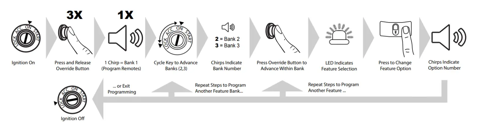
- Turn the ignition
- Press and release the valet button three (3)
- The system will beep one (1) time, indicating you have accessed Bank
- Each cycle of the Ignition, OFF/ON, will advance to the next bank (up to Bank 3) then restart at Bank(Note: To re-access Bank 1 for transmitter programming, you will need to exit and re-enter programming mode.)
- The system will beep a number of times to indicate the Bank number:• 1 beep: Bank 1 – Programming Remote Controls• 2 beeps: Bank 2 – Security Control Options• 3 beeps: Bank 3 – Remote Start Control Options
- Once you have accessed the desired bank, press the valet button to advance through The LED will flash a number of times to indicate the feature, based on the charts that follow this section. The system will chip a number of times to indicate the Option programmed.
- Once you have accessed the desired feature, press the LOCK button on the remote control to advance through the feature’s setting The system will beep a number of times to indicate the Options setting, based on the charts that follow this section.
- Once you have made the desired setting, you can press the valet button to advance through the features within the bank, or cycle the Ignition key OFF/ON to advance to the next
- Once you have completed programming, you MUST turn the ignition key to OFF to exit the programming Programming will automatically exit after sixty (60) seconds of inactivity.
Feature Bank Options
Bank 1: Transmitter Programming OptionsSee page 8 for a detailed description.
|
Feature Bank 1 |
Description |
||
| Channel | 1 | Auto Program/Lock | The press the Lock button on remote |
| 2 | Unlock | Press Unlock button on remote | |
| 3 | Trunk/Start | Press the Trunk/Start button on remote | |
| 4 | Ch. 4 AUX | Press button/buttons to control AUX Ch. 4 | |
| 5 | Ch. 5 AUX | Press button/buttons to control AUX Ch. 5 | |
| 6 | Ch. 6 AUX | Press button/buttons to control AUX Ch. 6 | |
| 7 | Ch. 7 AUX | Press button/buttons to control AUX Ch. 7 |
Bank 2: Security OptionsSee pages 9-12 for detailed descriptions.
|
Feature Bank 2 |
Options | |||||||
| 1Chirp | 2Chirp | 3Chirp | 4Chirp | 5Chirp |
6Chirp |
|||
|
Features |
1 | Lock / Unlock Function | 500ms | 3.5sec | 500ms L, DBL UL | DBL L, 500ms UL | DBL L, DBL UL | 500ms L, 350ms UL |
| 2 | Ignition Lock | OFF | ON | |||||
| 3 | Ignition Unlock | OFF | Unlock All | Unlock Driver | ||||
| 4 | Exterior Illumination | OFF | With Arm | With Disarm | With Arm & Disarm | |||
| 5 | Auto Relock | OFF | Auto-Lock Only | Auto-Lock & Arm | ||||
| 6 | Auto Arming / Locking | OFF | Auto Arm Only | Auto-Lock & Arm | ||||
| 7 | Notification Sound | Both | Siren | Horn | ||||
| 8 | Horn Timing | 16ms | 30ms | 40ms | 50ms | 10ms | ||
| 9 | Valet Override Method | Valet | Custom Code | Stand Alone Valet | ||||
| 10 | Driver Priority Unlock | OFF | ON | |||||
| 11 | Silent Choice | OFF | From Transmitter | OEM Style | ||||
| 12 | Security Profile | All On | Doors off | Hood/trunk Off | All Off | All On w/ OEM RS | ||
| 13 | Door Trigger Input | Negative | Positive | |||||
| 14 | Park Light / Trunk Swap | OFF | ON | |||||
| 15 | Data Port Protocol | ADS | DBI | |||||
| 16 | Dome Light Delay Timer | OFF / Program | 15sec | 30sec | 45sec | 60sec | 120sec | |
| 17 | Alarm Trigger Length | 30sec | 45sec | 60sec | 90sec | 120sec |
Bank 3: Remote Start OptionsSee pages 13-16 for detailed descriptions.
|
Feature Bank 3 |
Options | ||||||
| 1Chirp | 2Chirp | 3Chirp | 4Chirp | 5Chirp |
6Chirp |
||
|
Features |
1 | Defrost Output | Pulsed | 10min | RS Runtime | ||
| 2 | RS Start Notification | ON | OFF | ||||
| 3 | RS Runtime | 15min | 20min | 45min | 60min | 5min | 10min |
| 4 | RS Parking Lights | Steady | Flashing | ||||
| 5 | Engine Confirmation | Tach | Voltage | Data | Hybrid | ||
| 6 | Voltage Level | >0.5v B4 Start | <0.5v B4 Start | ||||
| 7 | Ignition 2 Output | Ignition | Accessory | Start | |||
| 8 | Ignition 3 Output | Ignition | Accessory | Start | |||
| 9 | Accessory Output | Accessory | Ignition | Start | |||
| 10 | Transmission | Auto | Manual | ||||
| 11 | Max Crank Time | 0.8sec | 1.0sec | 1.5sec | 2.0sec | 3.0sec | 4.0sec |
| 12 | Diesel Delay | OFF | Diesel 5 | Diesel 10 | Diesel 15 | Diesel 20 | Diesel 30 |
| 13 | Temperature Start | OFF | 14F | 5F | 0F | -4F | -14F |
| 14 | Crank Duration | Averaging | Preset | ||||
| 15 | RS Shock Override | Shunt until Clear | Shunt RS Cycle | Shunt From TX | |||
| 16 | Turbo Timer | OFF | 3min | 5min | 10min | ||
| 17 | Start Activation | Two Press | One-Press | Three Press | |||
| 18 | RS Lock Function | No Change | UL Before L After | UL Before Start | Lock After Start | ||
| 19 | Factory Disarm Output | Single Pulse | Double Pulse | 350ms | 500ms | 800ms | Same As Bank 2, F1 |
| 20 | Additional Unlock Pulse | No Pulse | IGN, ACC, GWR | IGN,ACC,GWR,PASD |
Programming & Diagnostics
Data Port Protocol Selection
The default data port protocol of this model is ADS (iDatalink 2-Way). This model is capable of detecting the correct data port protocol (ADS or DBI) and automatically configuring Feature Bank 2; Feature 18. To initialize the detection procedure:
- Press and hold the valet
- Cycle the vehicle’s Ignition ON/OFF two (2)
- Release the valet
Note: This feature is only available on module firmware v2.0 or higher.
Tach Function
When using the GREEN/ORANGE tach wire, the vehicle tach rate must be programmed.Programming with valet button when tach wire is connected:
- Turn the ignition key to the ON
- Press and release the valet button three (3)
- Immediately turn the ignition key
- Press and hold the valet button, then start the vehicle using the
- When the unit senses the tach signal, the parking lights will begin to
- Allow the vehicle to settle to a normal idle
- Release the valet
The parking lights will turn on for two (2) seconds and one (1) long chip will indicate that the learned tach signal is stored and the unit has exited tach learn mode.Programming without valet button when tach wire is connected:
- Turn the ignition key to the ON position and start the vehicle’s
- Wait for Engine RPM to lower to a normal
- Press and hold the vehicle’s brake
- Press the LOCK button on the OEM remote or the Carlin
The vehicle’s parking lights will flash seven (7) times to indicate the tach signal has been learned. If the parking lights do not flash, locate another tach source and repeat steps 1 – 4 above.Note: Programming tach signal via OEM or Telematics control is only available on Firmware v1.47 or Higher.
Dome Light Delay
To program the Prestige system to wait until the dome light turns off before arming:
- Close all
- With the vehicle ignition off, press LOCK, UNLOCK, LOCK, UNLOCK, LOCK, UNLOCK, LOCK on the remote The dash-mounted LED will turn on.
- Immediately OPEN then CLOSE the door WITHOUT disarming the After the dome light turns off, the LED will flash to indicate programming completion.
- Disarm and exit the
To return the system to default dome light sensing:
- Turn the vehicle ignition ON then OFF three (3) times, then press and hold the valet button for five (5)
- The system will beep one (1) time indicating the learned delay has been
2 /4 Hour Timed Start
- Press and hold the valet
- Cycle the vehicle’s Ignition ON/OFF one (1)
- Release the valet
- Within ten (10) seconds, press and release the valet button two (2) or four (4) times. The vehicle’s parking lights will flash two (2) or four (4) times to indicate the timer
To activate two (2) and four (4) hour timers:
- Cycle the vehicle’s Ignition ON/OFF one (1)
- Within ten (10) seconds, press and release the Start button on the remote control four (4)
The vehicle’s parking lights will flash four (4) times to indicate the timer is activated. The vehicle will automatically start every two (2) or four (4) hours as programmed for a maximum of forty-eight (48) hours. To cancel 2/4 hour timer mode, start the vehicle using the remote control or the vehicle’s Ignition key.
Turbo Timer
This model is equipped with a Turbo Timer. This feature will automatically engage the remote start to keep the vehicle’s engine running. This will allow for the engine to properly cool down and circulate fluids through the vehicle’s Turbo Charger. The Turbo Timer duration must be selected in Feature Bank 3 before it can be activated by the user.To activate the Turbo Timer:
- Start with the vehicle’s engine running for at least fifteen (15)
- Apply the vehicle’s Parking
- Press and release the valet button two (2) The vehicle’s parking lights will flash two (2) times for confirmation.
- Release and apply the vehicle’s parking
To use the Turn Timer feature:
- With the engine running, activate the vehicle’s Parking
- Release the vehicle’s brake
To cancel the Turbo Timer feature, press and release the vehicle’s brake pedal or use the Start function on the remote control. To prevent the Turbo Timer feature from engaging, press and hold the brake pedal while setting the vehicle’s Ignition to the OFF position.
Silent Arm and Disarm
Program the Prestige system to arm and disarm without notification beeps. (The siren will sound if the system is triggered while armed.)
- Turn the ignition ON then
- Press and release the valet button three (3) The system will respond with one (1) beep for ON or two (2) beeps for OFF.
User Selectable LED
This feature will control whether the LED is ON or OFF when the system is Armed/Locked. This will be selectable in feature programming OR on-the-fly without entering the programming feature banks.
- Turn the ignition ON, OFF, ON, OFF.
- Press and hold the valet button for five (5) seconds.
The LED will flash one (1) time for ON, two (2) times for OFF. This feature will not affect LED flash during programming.
Adjusting the Shock Sensor
- Arm the system, wait 5-10 seconds, then with an open palm carefully apply impact to areas of the vehicle to test the shock sensor’s sensitivity.
- To adjust, turn the adjustment knob on the shock sensor counter-clockwise for less sensitivity; clockwise for more
- If the proper sensitivity still cannot be achieved, re-locate the shock sensor.
Troubleshooting Trigger Zones
Test the doors, hood, trunk, and shock-sensor to ensure they trigger the security system. Once triggered, the LED flashes to indicate the trigger source:
| 1 | Shock |
| 2 | Trunk / Hood |
| 3 | Door |
Troubleshooting Remote Start
All Prestige remote start systems will provide parking light feedback to display remote start errors or shutdowns. The vehicle parking lights will flash to display error or shutdown code.
| 1 | Runtime Expired |
| 2 | Remote Shutdown |
| 3 | Brake On |
| 4 | Manual Mode |
| 5 | Hood Open |
| 6 | Low / No Tach |
| 7 | Tach Programming |
| 8 | High Tach |
Alarm Override Procedures
Valet Alarm OverrideThe Valet Override procedure will disable the alarm when the remote is not available or has become inoperative. If the vehicle door is opened without disarming, the alarm will sound and the vehicle will not start when attempting to start with the key. To disable the alarm:
- Turn the vehicle ignition to ON.
- Within five (5) seconds, press and release the valet button on the Antenna one (1) time.
The alarm will silence and the vehicle will now start normally with the key.Custom Code OverrideUnlike the default Valet Override, Custom Code Override is a user personalized code that offers a higher level of security. If the user chooses to use Custom Code Override, Feature Bank 2; Feature 9 must be programmed for “Custom Code”. Once the option has been selected the code must be programmed. Once the Custom Code is programmed it cannot be changed without first disarming the alarm.Custom Code Override ProcedureThe Custom Code is made up of 2 numbers. Each chosen number must be between digits 1-9. The default Custom Code is “11”. To disarm the alarm using the Custom Code option:
- Turn the vehicle ignition to ON.
- Within five (5) seconds, Press the valet button one (1) time.
- Within five (5) seconds, Turn the ignition OFF/ON.
- Within five (5) seconds, Press the valet button one (1) time.
- Turn the vehicle ignition to OFF then ON to start the vehicle.
Custom Code Programming ProcedureIn this example, the user has selected Custom Code “23”. To program a user-selected custom code starts with the alarm disarmed:
- Turn the ignition to the ON position
- Within ten (10) seconds, press the valet button three (3) times to enter programming.
- Within ten (10) seconds, Cycle the ignition OFF/ON, OFF/ON, OFF/ON. The system will beep one (1) time.
- Within ten (10) seconds, Press the valet button two (2) times. This number will indicate the first digit of the chosen Custom Code.
- Within ten (10) seconds, Cycle the ignition OFF/ON.
- Within ten (10) seconds, Press the valet button three (3) times. This number will indicate the second digit of the chosen Custom Code.
- Cycle the ignition OFF.
If the Custom Code was accepted the LED will flash the first number (2), pause, then the second number (3). This will repeat two (2) more times to confirm the Custom Code entry. If after 15sec the LED does not flash please repeat steps 1-7.Stand Alone OverrideStand Alone Valet Override is an option available to override the alarm without the use of the valet button. This requires Feature Bank 2, Feature 9 to be programmed for “Stand Alone Valet”. Once programmed, disarm the alarm without the use of the remote or valet button:
- Within five (5) seconds, Cycle the ignition ON, OFF, ON.
- Within five (5) seconds, press the brake pedal three (3) times
Wiring Diagrams
Door Lock Connections
Positive-Trigger Door LocksVerification: The vehicle wires register 12V+ when the Lock and Unlock switches are activated.
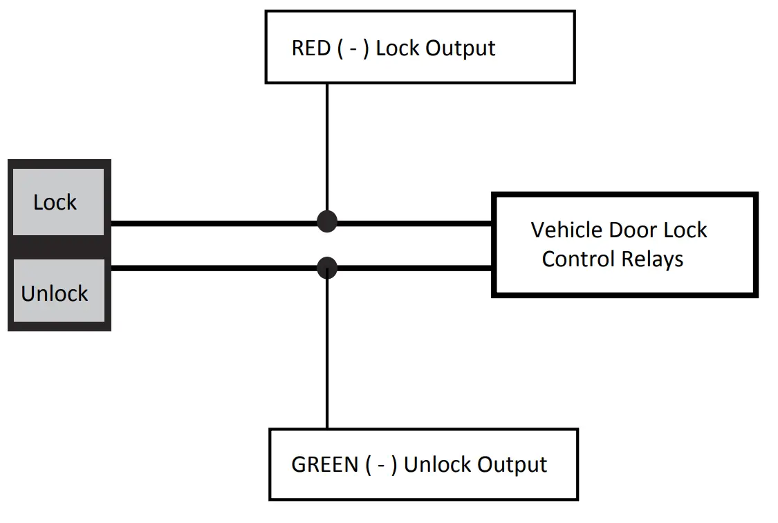
Positive-Trigger Door LocksVerification: The vehicle wires register 12V+ when the Lock and Unlock switches are activated.
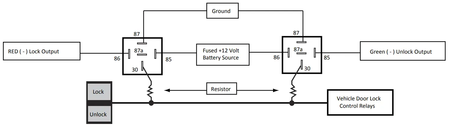
Single-Wire Negative Multiplex Door Locks (Relays required)Verification: The vehicle wire registers variable Ground values when the Lock and Unlock switches are activated. Please consult the vehicle-specific wire and location chart for resistor values.
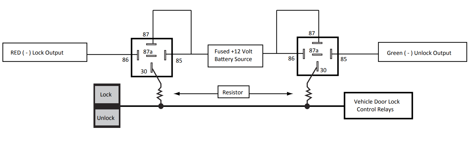
Single-Wire Positive Multiplex Door Locks (Relays required)Verification: The vehicle wire registers variable 12V+ values when the Lock and Unlock switches are activated. Please consult the vehicle-specific wire and location chart for resistor values.
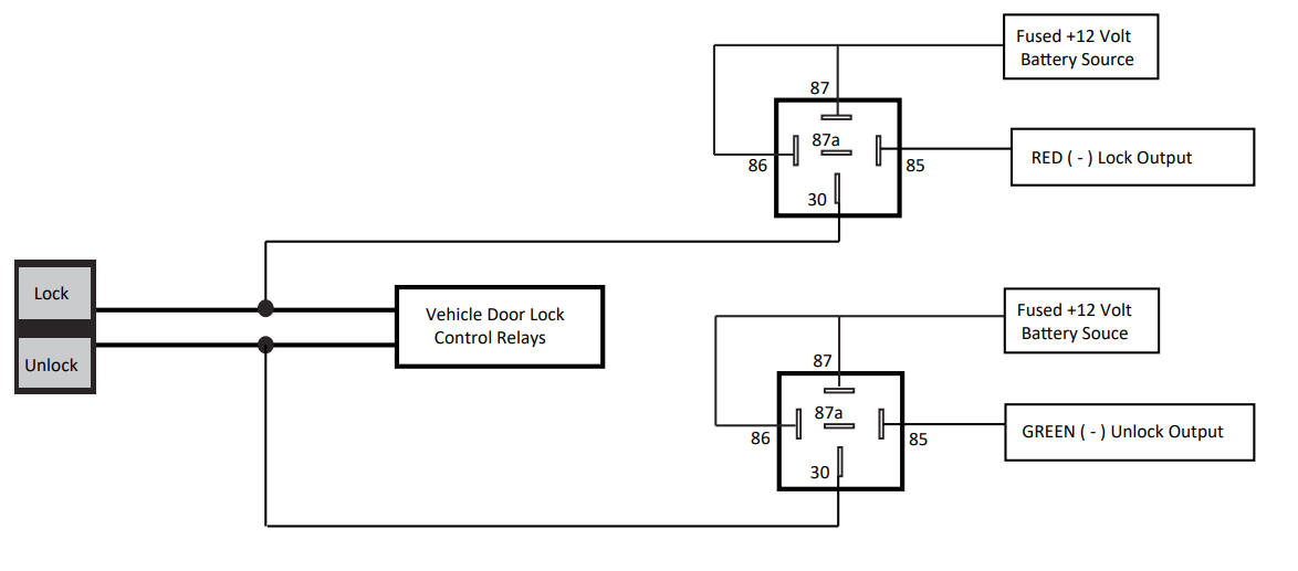
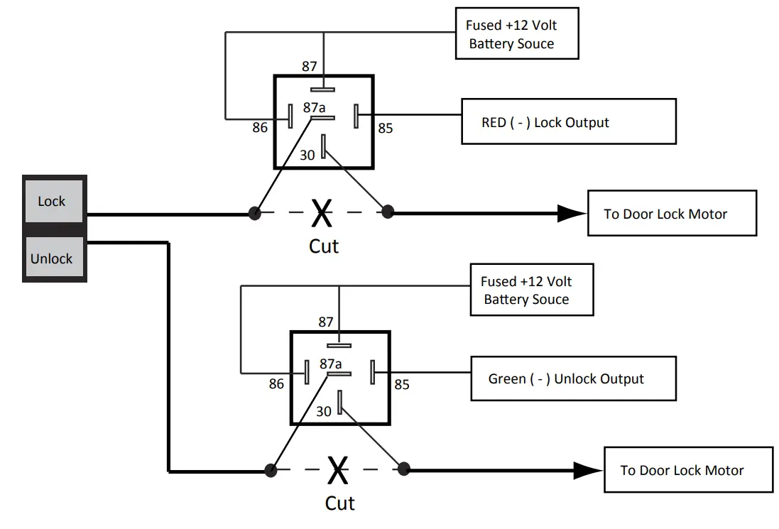
Reverse-Polarity Door Locks (Relays required)Verification: The vehicle wires rest on the Ground and register 12V+ when the Lock and Unlock switches are activated.
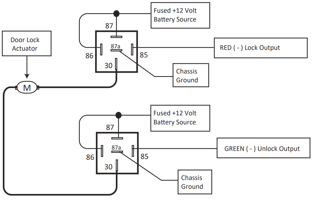
Aftermarket Actuators (Relays and door lock actuators required)
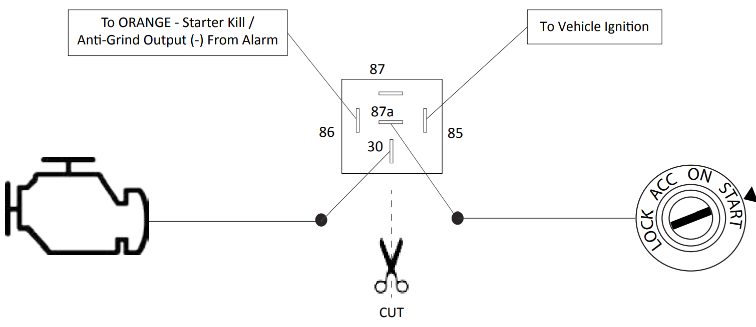
Starter Kill / Anti-Grind Relay Connections
Starter Kill / Anti-Grind Relay (Optional)
Full System Connections
report this ad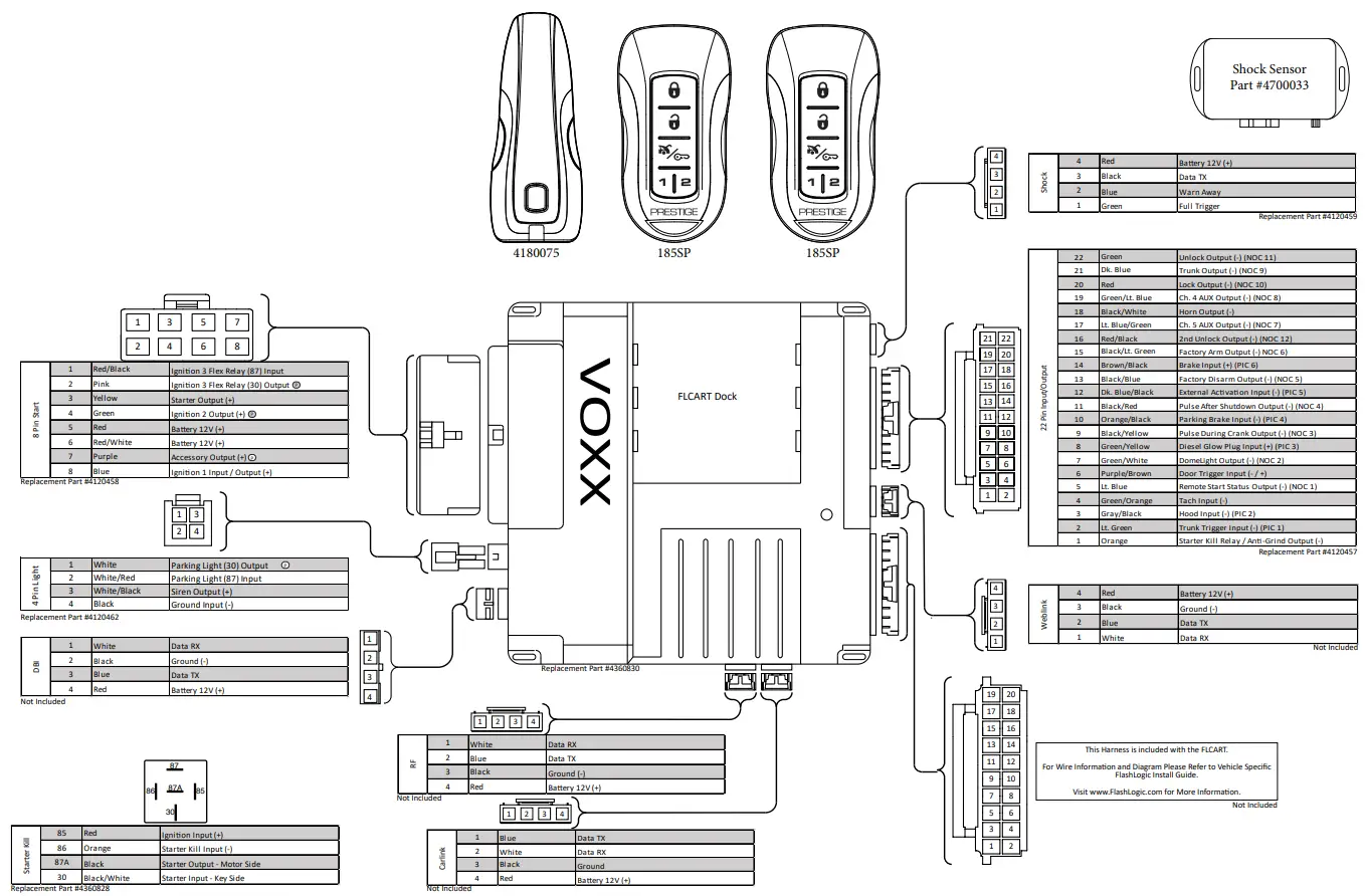
References
[xyz-ips snippet=”download-snippet”]