![]()
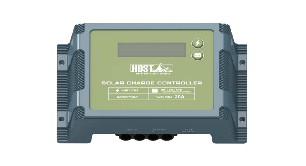
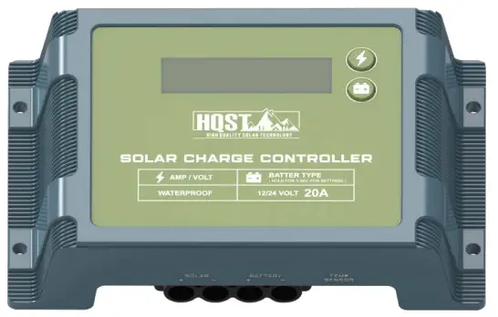
![]() Waterproof Solar Charge Controller20A PWMVersion 1.0
Waterproof Solar Charge Controller20A PWMVersion 1.0
![]() Important Safety Instructions
Important Safety Instructions![]() Please save these instructions.
Please save these instructions.
This manual contains important safety, installation, and operating instructions for the charge controller. The following symbols are used throughout the manual:
WARNINGIndicates a potentially dangerous condition. Use extreme caution when performing this task
CAUTIONIndicates a critical procedure for safe and proper operation of the controller
NOTEIndicates a procedure or function that is important to the safe and proper operation of the controller
General Safety Information
- Read all the instructions and cautions in the manual before beginning the installation.
- There are no serviceable parts for this controller. Do NOT disassemble or attempt to repair the controller.
- Make sure all connections going into and from the controller are tight. There may be sparks when making connections, therefore, make sure there are no flammable materials or gases near the installation.
Charge Controller Safety
- NEVER connect the solar panel array to the controller without a battery.The battery must be connected first. This may cause a dangerous occurrence where the controller would experience a high open-circuit voltage at the terminals.
- Ensure PV input voltage does not exceed 55V VDC to prevent permanent damage. Use the Open Circuit (Voc) to make sure the voltage does not exceed this value when connecting panels together in series.
Battery Safety
- Lead-acid and LiFePO4 batteries can be dangerous. Ensure no sparks or flames are present when working near batteries. Refer to the battery manufacturer’s specific charging rate setting. Do NOT charge improper battery type.
- Never attempt to charge a damaged battery, frozen battery, or non-rechargeable battery.
- Do NOT let the positive (+) and negative (-) terminals of the battery touch each other.
- Use only sealed lead-acid, flooded, gel or LiFePO4 batteries that must be a deep cycle.
- Explosive battery gases may be present while charging. Be certain there is enough ventilation to release the gases.
- Be careful when working with large lead-acid batteries. Wear eye protection and have fresh water available in case there is contact with the battery acid.
- Over-charging and excessive gas precipitation may damage the battery plates and activate material shedding on them. Too high of an equalizing charge or too long of one may cause damage. Please carefully review the specific requirements of the battery used in the system.
- If battery acid contacts skin or clothing, wash immediately with soap and water. If acid enters the eye, immediately flush the eye running with cold water for at least 10 minutes and get medical attention immediately.
WARNING
Connect battery terminals to the charge controller BEFORE connecting the solar panel(s) to the charge controller. NEVERconnect solar panels to the charge controller until the battery is connected.
General Information
The Voyager is an advanced PWM charge controller suitable for 12/24VV solar system applications. It features an intuitive LCD displaying information such as charging current and battery voltage, as well as an error code system to quickly diagnose potential faults. The Voyager is completely waterproof and suitable for charging up to 4 different battery types, including Lithium.
Key Features
- Smart PWM technology, high efficiency with reawakening Lithium feature
- Backlit LCD displaying system operating information and error codes
- 4 Battery Type Compatible – Gel, AGM, Flooded, Lithium
- Waterproof design, suitable for indoor or outdoor use
- 4-Stage PWM Charging: Bulk, Absorption, Float, & Equalization
- Protections: Multiple Battery, Controller, and PV electronic protections The common positive charge controller
Identification of Parts
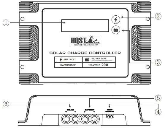
Key Parts
| ① Backlit LCD② AMP/VOLT Button③ BATTERY TYPE Button | ④ Remote Temperature Sensor Port⑤ Battery Terminals⑥ Solar Terminal |
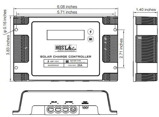
Dimensions
Optional Component
The Voyager is shipped by itself with no additional components. Optional components that require a separate purchase:
Voyager Temperature Sensor: Measures the temperature at the battery and uses this data for very accurate temperature compensation. The sensor is supplied with a 9.8ft cable length that connects to the charge controller. Simply connect the cable and adhere the sensor on top or the side of the battery to record ambient temperature around the battery.
Installation
WARNING
Connect battery terminal wires to the charge controller FIRST then connect the solar panel(s) to the charge controller. NEVER connect a solar panel to the charge controller before the battery.
CAUTIONDo not over-torque or over-tighten the screw terminals. This could potentially break the piece that holds the wire to the charge controller.Refer to the technical specifications for max wire sizes on the controller and for the maximum amperage going through wires.
Mounting Recommendations:
WARNINGNever install the controller in a sealed enclosure with flooded batteries. Gas can accumulate and there is a risk of explosion Voyager is designed for vertical mounting on a wall.
- Choose Mounting Location—place the controller on a vertical surface protected from direct sunlight, high temperatures, and water. Make sure there is good ventilation.
- Check for Clearance—verify that there is sufficient room to run wires, as well as clearance above and below the controller for ventilation. The clearance should be at least 6 inches (150mm).
- Mark Holes
- Drill Holes
- Secure the charge controller
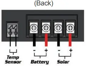
WiringThe Voyager has 4 terminals which are clearly labeled as “solar” or “battery”.
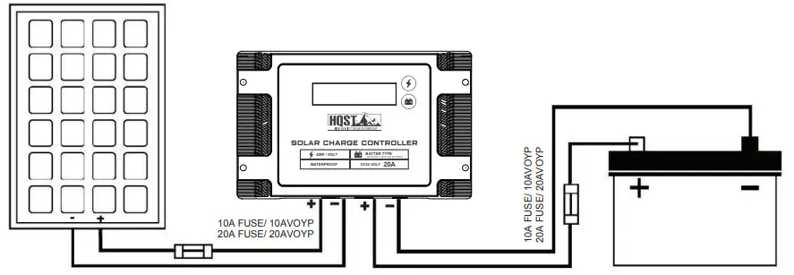
NOTEThis assumes one 100W panel. The fuse before the charge controller will change depending on the number of solar panels connected.
Cable Sizing
Distance Wiring
| Cable Total Length One-Way Distance | < 10ft | 10ft-20ft |
| Cable Size (AWG) | 14-12AWG | 12-10AWG |
NEC Maximum Current for different Copper Wire Sizes
| AWG | 16 | 14 | 12 | 10 | 8 | 6 | 4 | 2 | 0 |
| Max.Current | 10A | 15A | 20A | 30A | 55A | 75A | 95A | 130A | 170A |
Operation
After connecting the battery to the charge controller, the controller will turn on automatically. Assuming normal operation, the charge controller will cycle through different displays. They are as follows:
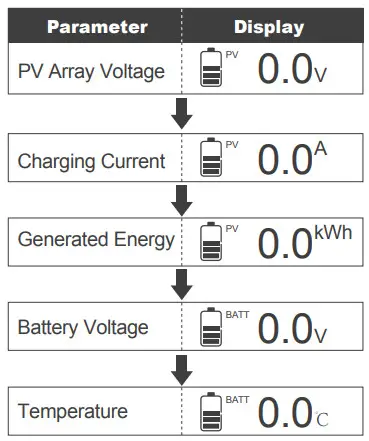
The Voyager is an easy-to-use controller requiring minimal maintenance. The user can adjust some parameters based on the display screen. The user can manually cycle through the display screens by using the”AMP/VOLT” and “BATTERY TYPE” buttons
| AMP /VOLT | Cycles forward through the different display screens. | |
| BATTERYTYPE | Cycles backward through the different select screens & Customize some parameters on the charge controller |
Change the Parameters
NOTEThe screen must be at the appropriate interface in order to change the specific parameter.
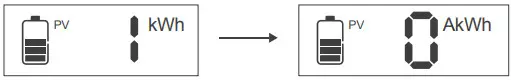
- Clear overall power generation to 0 KWhThe user can cycle to the KWh screen by pressing “BATTERY TYPE” or “AMP/VOLT” and in order to reset the current power generation back to 0 kWh the user must hold down “BATTERY TYPE”

- Selecting Battery TypeWARNINGIncorrect battery type settings may damage your battery. Please check your battery manufacturer’s specifications to when selecting battery type.NOTEIf selecting Lithium and wanting to set Battery Voltage or Charge Parameters, go to “4. Select lithium Battery Voltage and Charge Voltage,” later in this table.SEL is referring to Sealed and AGM batteryIn the screen showing the battery voltage, hold down “BATTERY TYPE” for approximately 3-5 seconds before the screen flashes the current battery type.Once flashing, use the “AMP/VOLT” button to select the proper battery type and then hold down “BATTERY TYPE” again to lock in the selected battery type.
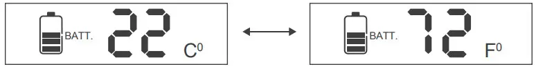
- Change from C° to F°In the screen showing the temperature of the controller or remote temperature sensor, the user can hold down the “BATTERY TYPE” button for approximately 3-5 seconds to switch from Celsius to Fahrenheit or vice versa.
- Select Lithium Battery Voltage and Charge VoltageIn the screen showing the battery voltage, hold down “BATTERY TYPE” for approximately 3-5 seconds before the screen flashes the current battery type. Once flashing, use the”AMP/VOLT” button to highlight LI.Once LI is flashing, tap the “BATTERY TYPE” button and a 12V will flash in the screen.If you want 12V LI charging, then select the “BATTERY TYPE” again to move to LI Boost Charging Voltage. If you want a 24V LI charging, then you select “AMP/VOLT”to move from 12V to 24V LI Charging. Once you confirm your LI Charging (12V or 24V) press “BATTERY TYPE” to move to LI Boost Charging Voltage.Press “AMP/VOLT” to change the Boost Voltage. The default setting is 14.2V and the user can set it in the range 2.6~16.0V, in 0.2V increments. Oncedone, hold “BATTERY TYPE” to confirm the selection. The setting will also be automatically saved after 15 seconds without holding “BATTERY TYPE”.

 Once LI is flashing, tap the “BATTERY TYPE” button and a 12V will flash in the screen.
 If you want 12V LI charging, then select the “BATTERY TYPE” again to move to LI Boost Charging Voltage. If you want a 24V LI charging, then you select “AMP/VOLT”to move from 12V to 24V LI Charging. Once you confirm your LI Charging (12V or 24V) press “BATTERY TYPE” to move to LI Boost Charging Voltage.
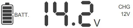 Press “AMP/VOLT” to change the Boost Voltage. The default setting is 14.2V and the user can set it in the range 2.6~16.0V, in 0.2V increments. Oncedone, hold “BATTERY TYPE” to confirm the selection. The setting will also be automatically saved after 15 seconds without holding “BATTERY TYPE”.
NOTEPlease note if choosing a 24V LI battery setting, the boost charging voltages will still be shown in their 12V values. Multiplythe value by 2 to find out 24V charging voltage.
System Status Icons
| Icon | Behavior |
| Constant: The system is normal, but it is not charging | |
| Charging: The bars will be sequencing indicating the system is charging. | |
| Constant: The battery is at full charge. | |
| Flashing: The battery is overvoltage. | |
 |
Flashing: The battery is under voltage. |
| Flashing: The bars are sequencing, indicating the controller is activating an over-discharged lithium battery. | |
 |
Constant: System error. |
Four Charging Stages
The Voyager has a 4-stage battery charging algorithm for rapid, efficient, and safe battery charging. They include Bulk Charge, Boost Charge, Float Charge, and Equalization.PWM TechnologyThe Voyager utilizes Pulse Width Modulation (PWM) technology for battery charging. Battery charging is a current-based process so controlling the current will control the battery voltage. For the most accurate return of capacity, and for the prevention of excessive gassing pressure, the battery is required to be controlled by specified voltage regulation set points for Absorption, Float, and Equalization charging stages. The charge controller uses automatic duty cycle conversion, creating pulses of current to charge the battery. The duty cycle is proportional to the difference between the sensed battery voltage and the specified voltage regulation set point. Once the battery reached the specified voltage range, pulse current charging mode allows the battery to react and allows for an acceptable rate of charge for the battery level.
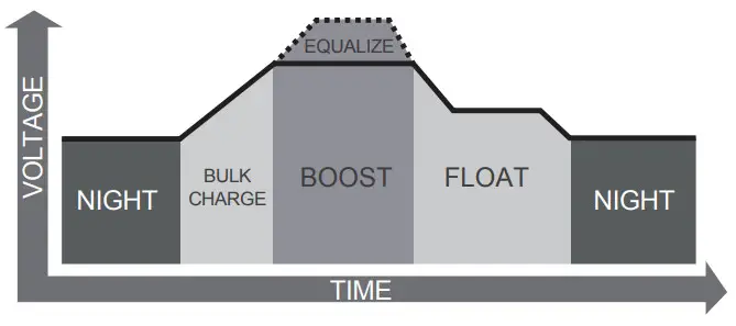
Bulk Charge: This algorithm is used for day-to-day charging. It uses 100% of available solar power to recharge the battery and is equivalent to constant current.Boost Charge: When the battery has charged to the Boost voltage set-point, it undergoes an absorption stage which is equivalent to constant voltage regulation to prevent heating and excessive gassing in the battery. The Boost time is 120 minutes.Float Charge: After Boost Charge, the controller will reduce the battery voltage to a float voltage set point. Once the battery is fully charged, there will be no more chemical reactions and all the charge current would turn into heat or gas.Because of this, the charge controller will reduce the voltage charge to a smaller quantity, while lightly charging the battery. The purpose of this is to offset the power consumption while maintaining a full battery storage capacity. If a load drawn from the battery exceeds the charge current, the controller will no longer be able to maintain the battery to a Float set point and the controller will end the float charge stage and refer back to bulk charging.Equalization: Is carried out every 28 days of the month. It is intentional overcharging of the battery for a controlled period. Certain types of batteries benefit from periodic equalizing charges, which can stir the electrolyte, balance battery voltage and complete chemical reactions. Equalizing charge increases the battery voltage, higher than the standard complement voltage, which gasifies the battery electrolyte.
WARNINGOnce equalization is active in the battery charging, it will not exit this stage unless there is adequate charging current from the solar panel. There should be NO load on the batteries when in equalization charging stage.Over-charging and excessive gas precipitation may damage the battery plates and activate material shedding on them. Too high of equalizing charge or for too long may cause damage. Please carefully review the specific requirements of the battery used in the system.
Lithium Battery ActivationThe Voyager PWM charge controller has a reactivation feature to awaken a sleeping lithium battery. The protection circuit of Li-ion battery will typically turn the battery off and make it unusable if over-discharged. This can happen when storing a Li-ion pack in a discharged state for any length of time as self-discharge would gradually deplete the remaining charge. Without the wake-up feature to activate and charge batteries, these batteries would become unserviceable and the packs would be discarded. The Voyager will apply a small charge current to activate the protection circuit and if a correct cell voltage can be reached, it starts a normal charge.
CAUTIONWhen using the Voyager to charge a 24V lithium battery bank, set the system voltage to 24V instead of auto recognition. Otherwise, the over-discharged 24V lithium battery will not be activated.
WARNINGIncorrect battery type setting may damage your battery.Over-charging and excessive gas precipitation may damage the battery plates and activate material shedding on them. Too high of equalizing charge or for too long may cause damage. Please carefully review the specific requirements of the battery used in the system.
Troubleshooting
| Indicator | Description | Troubleshoot |
| Batteryover voltage | Use a multi-meter to check the voltage of the battery. Make sure the battery voltage is not exceeding the rated specification of the charge controller. Disconnect battery. | |
| Batteryunder voltage | Use a multi-meter to verify the rated battery voltage. Disconnect any loads connected to the battery to allow it to charge. | |
| Other Considerations | ||
| Charge controller does not charge during daytime when the sun is shining on the solar panels. | Confirm that there is a tight and correct connection from the battery bank to the charge controller and the solar panels to the charge controller. Use a multi-meter to check if the polarity of the solar modules has been reversed on the charge controller’s solar terminals. | |
| Everything is connected correctly, but the LCD on the controller does not turn on | Check the rated battery voltage. The LCD will not display on the charge controller unless there is at least 9V coming from the battery bank. |
Error Codes
| Error Number | Description |
| EO | No error detected |
| 0.00E+00 | Battery over-discharged |
| 0.00E+00 | Battery over-voltage |
| 0.00E+00 | Controller over-temperature |
| 0.00E+00 | Battery over-temperature |
| EDS | PV input over-current |
| El 0 | PV over-voltage |
| 0.00E+00 | PV reverse polarity |
| 0.00E+00 | Battery reverse polarity |
| El 5 | No Battery Detected |
Maintenance
For best controller performance, it is recommended that these tasks be performed from time to time.
- Check wiring going into the charge controller and make sure there is no wire damage or wear.
- Tighten all terminals and inspect any loose, broken, or burnt up connections
- Occasionally clean the case using a damp cloth
Technical Specifications
| Electrical Parameters | VOYP20 |
| System Voltage | 12V/24V Auto |
| Battery Rated Current | 20A |
| Max Battery Voltage | 32V |
| PV Input Voltage Range | 15V–55V |
| Max PV Input (Voc) | |
| Max Power Input | 12V @ 260W24V @ 520W |
| Power Consumption | 12V @ 0.24W24V @ 0.74W |
| Battery Types | SLD/AGM, GEL, FLD, LI |
| Electronic Protections | Battery / Controller Over-Temperature ProtectionPV / Battery Reverse Polarity, Over-Voltage,Over-Current Protection |
| Mechanical Parameters | |
| Grounding Type | Positive |
| Controller Terminals | 20-6 AWG, 2-pin terminals |
| Temperature Compensation | -3mV/ C /2V, excludes LI |
| Operating Temperature | -31°F —113°F |
| Storage Temperature | -31°F — 167°F |
| Operating / Storage Humidity | 10% — 90%, No Condensation |
| Protection Level | IP67 |
| Dimensions | 6.08 x 3.83 x 1.40 in |
| Weight | 0.55 lbs |
| Battery Charging Parameters GEL | SEALED | FLOODED | LITHIUM | |
| Over-voltage Warning | 16 V | |||
| Charging Limit Voltage | 15.5 V | 15.5 V | 15.5 V | 15.5 V |
| Over Voltage Reconnect | 15 V | 15 V | 15 V | 15 V |
| Equalization Voltage | – | 14.6V | 14.8V | – |
| Boost Voltage | 14.2 V | 14.4 V | 14.6 V | 14.2 V(User: 12.6-16 V) |
| Float Voltage | 13.8V | 13.8V | 13.8V | – |
| Boost Return Voltage | 13.2 V | |||
| Under Voltage Warning | 12 V | |||
| Under Voltage Recover | 12.2 V | |||
| Over-discharge Warning | 11.1 V | |||
| Over-discharge Recover | 12.6 V | |||
| Discharging Limit Voltage | 10.8 V | |||
| Equalization Duration | – | 2 hours | 2 hours | – |
| Boost Duration | 2 hours | 2 hours | 2 hours | – |
 report this ad
![]()
[email protected]800-390-9264
[xyz-ips snippet=”download-snippet”]