
INSTALLATION MANUALDual Monitor Wall Mount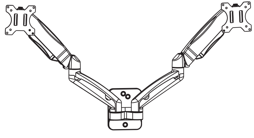
WARNING
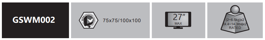
If you do not understand these directions, or if you have any doubts about the safety of the installation, please call a qualified technician. Check carefully to make sure there are no missing or defective parts. Improper installation may cause damage or serious injury. Do not use this product for any purpose that is not explicitly specified in this manual. Do not exceed weight capacity. This product is designed to be installed on wood stud walls, solid concrete walls or brick walls. Do not mount on drywall alone. We cannot be liable for damage or injury caused by improper mounting, incorrect assembly, or inappropriate use.
TIPOVER WARNING
SERIOUS OR FATAL CRUSHING INJURIES CAN OCCUR FROM TIPOVER. TO HELP PREVENT TIPOVER:
- NEVER ALLOW CHILDREN TO CLIMB, STAND. HANG. OR PLAY ON ANY PART OF MONITOR OR STAND.
- USE TIPOVER RESTRAINT OR ANCHOR STAND TO WALL.
USE OF MOYER RESTRAINTS MAY ONLY REDUCE, BUT NOT ILININATE RISK Of TT/ OVERSMALL PARTS- NOT FOR CHILDREN UNDER 3 YEARS. ADULT SUPERVISION IS REQUIRED.
Supplied Parts List
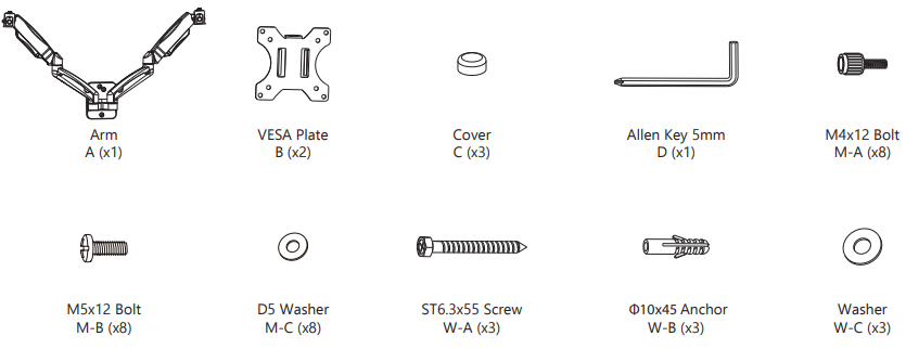
Step 1Option A Wood Stud1. If installing this product on wood stud, mark the position with Bubble Level & pencil on the wall.

2. Drill 3/16″(4.5mm) diameter x 2.2”(55mm) length holes at the marked position.
3. Attach the mount to wood stud and tighten using Screw W-A & D5 Washer W-C with a screwdriver. (Screwdriver not included)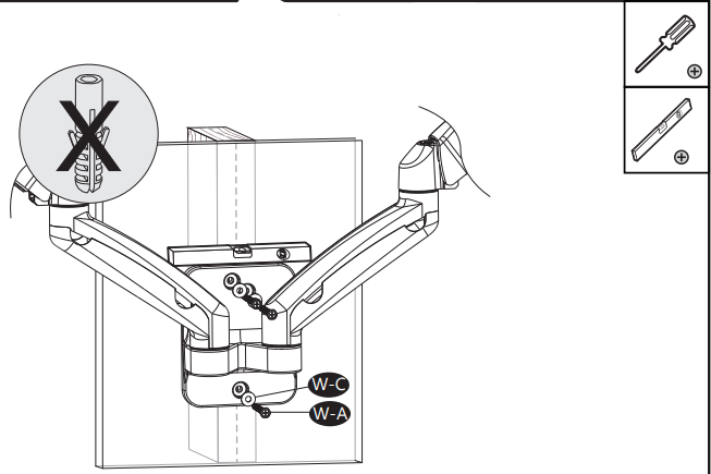
Option B Concrete Wall1. If installing this product on a concrete wall, mark the position with Bubble Level & pencil on the concrete wall.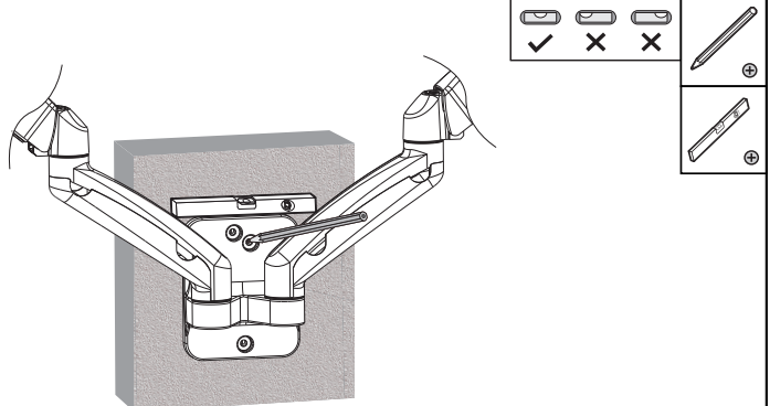
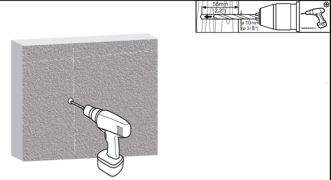
2. Drill 3/8″(10mm) diameter x 2.2”(55mm) length holes at the marked position.
3. Insert the Anchor W-B into the mounting holes. Attach the mount to the concrete wall and tighten using Screw W-A & Washer W-C with a screwdriver. (Screwdriver not included)
Step 2 Fix Cover C onto the front of the mount part.
 Step 3Step 3.1 Select TV Screws
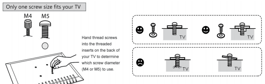
Step 3.2 Attach the VESA Plate B to your TV/Monitor, and thread M4x12 Bolt M-A or M5x12 Bolt M-B into the mountingholes with D5 Washer M-C, tighten with Allen Key 5mm D.
Step 4 Detach the Top Screw by threading it counterclockwise.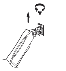
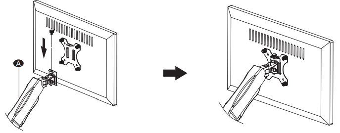
Step 5 Put the assembled TV/Monitor onto Arm A and ensure stability, tighten the VESA Plate B using Top Screw.
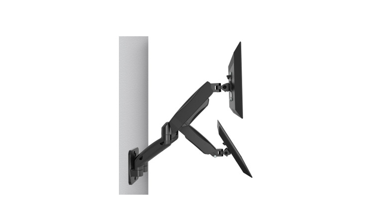
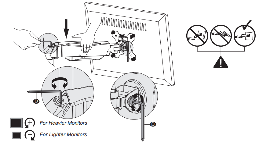
Step 6 Press the Arm A on the horizontal level as the image shown, adjust gas spring tension to your personal preference using Allen Key 5mm D . Adjust the tilt tension using Allen Key 5mm D.
- Insert the 5mm Allen Key into the adjusting hole and turn clockwise (-) to reduce gas spring tension, suitable for lighter screens.
- Insert the 5mm Allen Key into the adjusting hole and turn counter-clockwise (+) to increase gas spring tension, suitable for heavier screens.
- Please take note it may take numerous turns for gas spring tension adjustment.
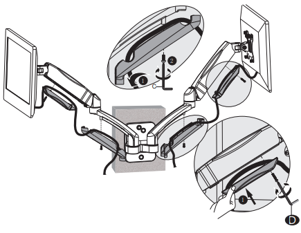
Step 7 Screw out the bolts with Allen Key 5mm D and take off the cable cases.

Step 8 Guide the cables through and put the cable cases back.
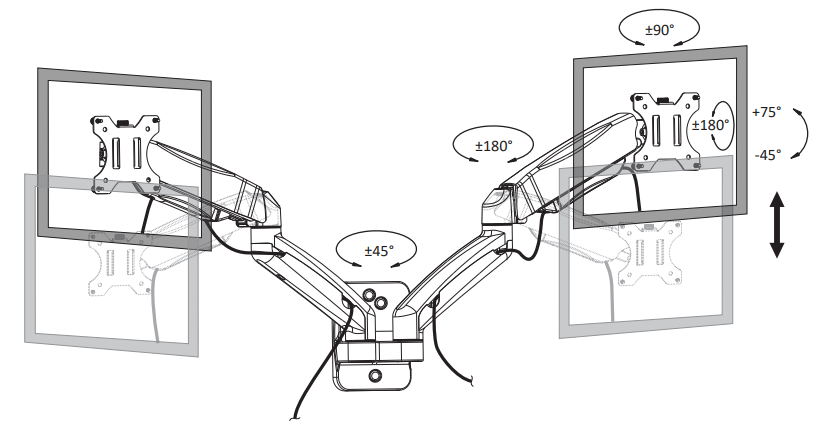
Step 9 Manually swivel, tilt, and rotate the monitor for the best viewing angle.
Thank you for Choosing usWe support the technology that brings your home to life.We offer high-quality products, professional customer service, and extensive technical support.If you have any questions, please contact us.1-844-SATTLER (18447288537)[email protected]www.walielectric.com
References
[xyz-ips snippet=”download-snippet”]