WaterMark Water Filter 4 Stage Installation Guide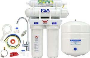
–
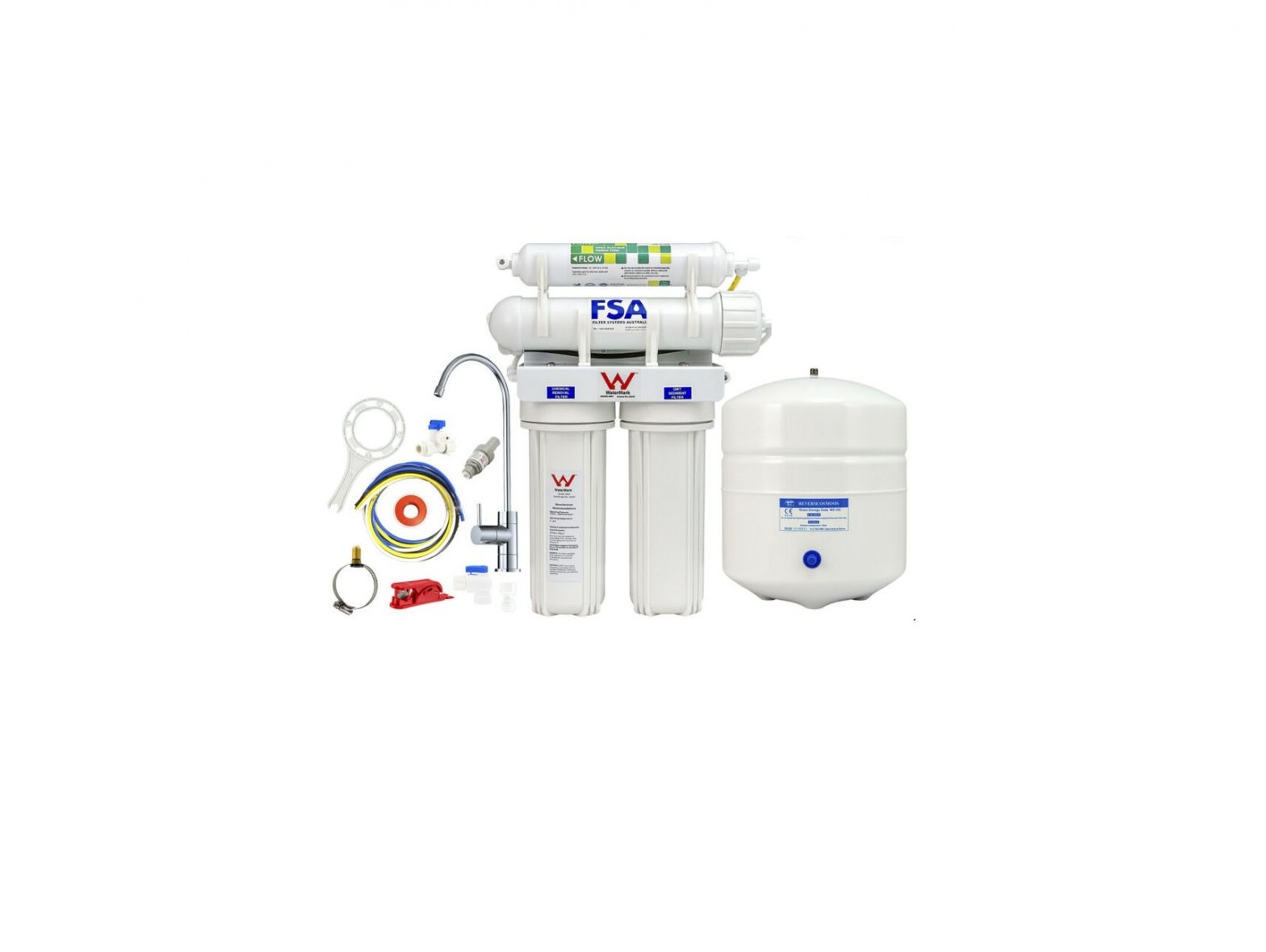
REVERSE OSMOSIS INSTALLATION Watermark 4 Stage
BRIEF TECHNICAL ASPECT OF THE WATER TREATMENT SYSTEMThe Water Filter Treatment System utilizes a process called reverse osmosis (RO). As the heart of the purification system, the RO process uses semi-permeable spiral-wound membranes to separate and remove dissolved solids, organic, pyrogens, sub-micron colloidal particles and bacteria from water. Feed water is delivered under pressure at about 60 PSI through the permeator where water permeates the minute pores of the membrane and is delivered as purified water. Impurities in the water are concentrated in the reject stream and flushed to drain. Your newly purchased Reverse Osmosis System is capable of removing between 90% to 96% of the total dissolved solids (TDS), organic, and bacteria.
WATERMARK CERTIFIED RO SYSTEM:
This RO system is certified to Watermark Standards AS/NZS 3497 Under the Certificate number 23247. Watermark certification is the level of certification required by law for a licensed plumber in Australia to install a water filter system. All products used under this certification will give you peace of mind knowing that your water filter complies with Australian plumbing codes.Our Watermark certified filter systems are hand assembled here in Australia and are randomly batch tested to ensure top quality and workmanship for your water filtration products.ImportantWe suggest you read and become familiar with all instructions, processes, and parts prior to proceeding with the installation.
BEFORE YOU START:
PLEASE NOTE – All components that come pre-assembled will require tightening and checking before installation. Due to transit, fittings and other components may be loosened or unseated from vibrations so please go along and check all things including but not limited to: Tubing, Fittings, tubing connections (between tube and fitting), O-rings, housings and filters.
Prior to installing the feed water assembly, please make sure that the following water conditions are met:
-
Feed Water Condition Min Max Inlet Pressure 40 PSI 100 PSI (Pressure Limiting Valve PLV required if pressure > 70PSI) Temperature` 40 deg. F 100 deg. F pH Level 2 11 TDS Level 0 ppm 2000 ppm - All local plumbing codes must be followed.
- All tubing must be cut in a straight line with a clean, sharp Stanley Knife.
Ready to start
- Locate cold water supply, suitable hanging and fitment room for system and tank. Locate the drain point, and sink faucet placement.
FEED WATER INSTALLATION:Locate cold-water flex line V2″ to cold water faucet tap on sink, turn off water supply,open cold water faucet to release the pressure.
Picture indicates accessing water via the V2″ flex line to cold water mixer tap. Thread tape must be applied when joining the valve to the adaptor block shown above. Please note that tubing colour on your systems is white, not blue as pictured. Picture shows PLV when PLV is provided. If PLV is not provided tubing is continuing through to the filter system NOTE; some models may contain this fitting. If so, this fitting is designed to replace the chrome Adaptor block and brass ball valve tap pictured above
DRAIN CLAMP INSTALLATION
- The drain clamp should be drilled, installed above the trap and on the vertical or horizontal tailpiece (see figure 2).
- The hole position on the pipe should be marked and drilled with a 1/4″ bit through one side of the pipe (see figure 3)
- Align the drain clamp over the drilled hole and attach it to the drainpipe and tighten the two screws evenly (see figure 4).Figure 3. Drain clamp drillDrain Saddle
 Figure 2. Drain Clamp Location
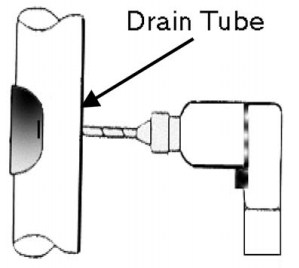 Figure 2. Drain Clamp Location
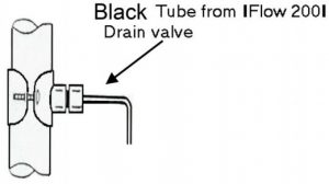
Fitting the Faucet to the sinkStainless Steel Sinks & Porcelain Sinks:
- Drilling through a stainless-steel sink can be achieved by marking a center punch and drilling a 3/16″ guide hole.
- Use a 1/2″ or 7/16″ carbide or very sharp drill to enlarge the hole.
- Make sure when starting to drill, begin slowly through the porcelain portion of the sink so that chipping is reduced to a minimum.
- On stainless steel, a very sharp drill bit and low speed is essential, or you risk burning the surface of the sink.
MOUNTING THE FAUCET:
- Disassemble the bottom portion of the faucet.
- Place into hole of sink and reassemble faucet from underneath sink
Assembling the System:
NOTE: New Models Now Come With Colour Coded Tubing
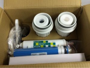
- STEP : Remove Components from Box, check all items are in box.
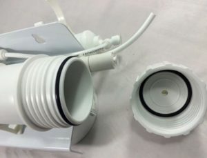
- STEP : Disconnect tubing from Membrane housing
- STEP : Un-screw membrane cap And ensure the o-rings are correctly Seated.
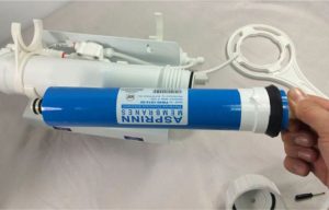
- STEP : Un-Wrap Membrane Ensure that you only handle the filter By the end stems.
- STEP: Firmly insert the membrane The end with the dual o-rings goes in First as shown.
- STEP : Tighten the membrane firmly A membrane spanner helps which can Be purchased from our online store.
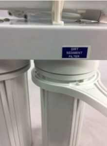
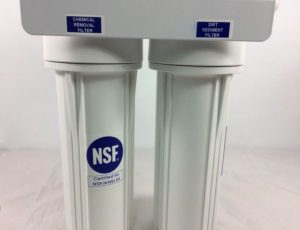
- STEP : Un-Wrap and load cartridges. The order from right to left is sediment then carbon as shown.
- STEP : Screw up the housings by hand in an upright position, ensure Filters line up correctly with housing
- STEP : Firmly tighten housings Using the provided spanner. The housings must be tight to avoid Leaks.
- STEP : The labels may not always


You are now ready for installation
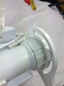
Connecting the RO system:Using Push-Fit fittings aka “John Guest” fittings:If you come across a push-fit fitting, you need to firmly push the tubing into the opening untilyou feel a “click” which signifies that the tubing has pushed through the internal O-ring and is seated correctly. If leaking occurs, it may be due to roughly cut tubing OR the tubing is not pushed in far enough. To remove tubing from push-fit fittings, depress the floating collet (shown in below photo), then pull the tubing out.
- Measure length of white tubing from your cold-water inlet (mains water inlet tee)
- Firmly push in tubing to the %” fitting on the Tee and screw tight to lock the tubing in.
- Firmly push the inlet tubing into the “Inlet” Of the RO system also labeled “DirtSediment Filter”
- Measure and cut length of Yellow tubing between the storage tank and Purefer Post Filter(Marked as “tank” on the Tee fitting.(NOTE: water goes in and out of the same line to the storage tank)
- Connect filtered water to Facet tap on sink With Blue Tubing(Refer to previous Faucet Installation)
SYSTEM START UP:
- Once you are confident that all components are assembled correctly, slowly turn on the inlet water and inspect the system thoroughly for leaks.
- Once system has been checked, open the valve on top of the storage tank and the system will kick back in and begin filling the tank full of Reverse Osmosis Water.NOTE: At NO point does the pressure valve on the bottom of the storage tank need to be tampered with or used. The water enters and exits the storage tank through the SAME LINE on the top of the tank. There is NO need to touch pressure valve at any point. The tank is preset to 7 PSI. Anything above or below that figure will cause to tank to not function as intended.
- IMPORTANT FOR 4 STAGE SYSTEMS: Allow the tank to fill to capacity BEFORE turning on the faucet on the sink. Once the tank is entirely full (approx. 1-2 Hours) open the sink top faucet and allow the entire tank to drain. This will flush the filters and the tubing prior to use. This is important as the filters are no longer pre-washed due to potential bacteria contamination. This process also helps to flush out the anti-bacterial solution which these units are factory treated with.
- The system will automatically start to fill the storage tank again.
- The system is ready to provide you with fresh and purified water. In some cases, there may be a lingering taste in the water, which can be described as a metallic or chemical taste, this is only the carbon and alkalizing fines or also some residual sanitizer in the tank or membrane and will disappear shortly after adequate flushing. If taste persists for longer than 1 week please contact us on 07 5597 4585
RECOMMENDED MAINTENANCE:
As a general rule, any cartridges BEFORE the membrane should be replaced every 6months. This will help ensure the membrane itself will perform to its full potential over its 1-5year lifespan (depending on water quality). The post carbon GAC (taste and odour cartridge) should be replaced every 12 months.On a standard 4 stage system, the changes would be similar to this:Poly Spun Sediment Cartridge – 6 monthsCarbon Block Cartridge – 6 monthsMembrane – 1-5 yearsPost Carbon – 12 monthspH neutral filter – 12 months (optional upgrade)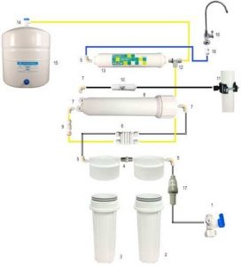
- GT14-14S – DM Fit Angle Stop Valve (Entry Tee)
- GT8-0S – Sediment Filter Housing
- GT8-0S – Carbon Filter Housing
- GT19-8S – 316 Stainless Steel Centre Joiner
- GT10-23G – Male 1/4″ Elbow – 1/4″ Tube
- GT13-4S – Automatic 4 Way Shut Off Valve
- GT10-13 – Male 1/8″ Elbow – 1/4″ Tube
- GT8-31 – Reverse Osmosis Membrane Housing
- GT10-17G – Inline Check Valve
- GT13-1S – Flow Restrictor (Waste Water)
- GT11-12G – 40mm Drain Saddle/Clamp
- GT10-125 – RO Tank Tee (Male 1/4″ – 2x 1/4″ Tube)
- GT6-21S – Post Inline Carbon GAC
- GT14-7 – Tank Valve
- GT13-47 – Water Storage Tank
- GT9-1S – Slim Goose Neck Faucet
- GT18-13 – Pressure Limiting Valve
- GT10-34 – Quick Connect Faucet Adaptor
![]() Yellow Tubing – RO Water
Yellow Tubing – RO Water![]() White Tubing – Unfiltered Water
White Tubing – Unfiltered Water ![]() Black Tubing – Waste Water
Black Tubing – Waste Water![]() Blue Tubing – Drinking Water
Blue Tubing – Drinking Water
Additional Extras:Water Hammer Arrestor: The water hammer arrestor is installed either at your washing machine or your dishwasher inlet. The Water Hammer Arrester has a 1/2″ BSP connection. Please refer to the provided brochure for further information.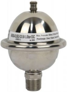 Pressure Relief Valve:The Pressure Relief valve is to prevent pressure due to thermal expansion. This commonly occurs when connecting the water to a fridge or water chiller/ice maker. This must be installed AFTER the Filter System. (I.E. Between the drinking water & Chiller/Fridge). It comes fitted with a drain clamp which clamps around the DOWN PIPE. This clamp has 2x ports, 1 for the pressure relief valve (pre-fitted) and the second one is for the waste water of the RO system. The waste water is located behind the filters on a small valve labeled drain line / Flow 200. This is the flow restrictor.
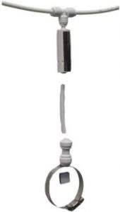 Please contact us on 07 5597 4585 if you have any questions in regards to the installation of this system BEFORE attempting.
WATERMARK CERTIFIED RO SYSTEM:
The three-stage pressurised component of this RO system is certified to Watermark Standards AS/NZS 3497 Under the Certificate number 23247. Watermark certification is the level of certification required by law for a licensed plumber in Australia to install a water filter system. All products used under this certification will give you peace of mind knowing that your water filter complies withAustralian plumbing codes. Our Watermark certified filter systems are hand assembled here in Australia and are randomly batch tested to ensure top quality and workmanship for your water filtration products.
AS/NZS 3497 Lic.No.23247
[xyz-ips snippet=”download-snippet”]