
![]() WAVES BSS®DPR-402COMPRESSOR / PEAK LIMITER / DE-ESSER
WAVES BSS®DPR-402COMPRESSOR / PEAK LIMITER / DE-ESSER
USER GUIDE
Chapter 1 – Introduction
Welcome
Thank you for choosing Waves! In order to get the most out of your new Waves plugin, please take a moment to read this user guide.To install software and manage your licenses, you need to have a free Waves account. Sign up at www.waves.com. With a Waves account, you can keep track of your products, renew your Waves Update Plan, participate in bonus programs, and keep up to date with important information.We suggest that you become familiar with the Waves Support pages: www.waves.com/support.There are technical articles about installation, troubleshooting, specifications, and more. Plus, you’ll find company contact information and Waves Support news.
About BSS
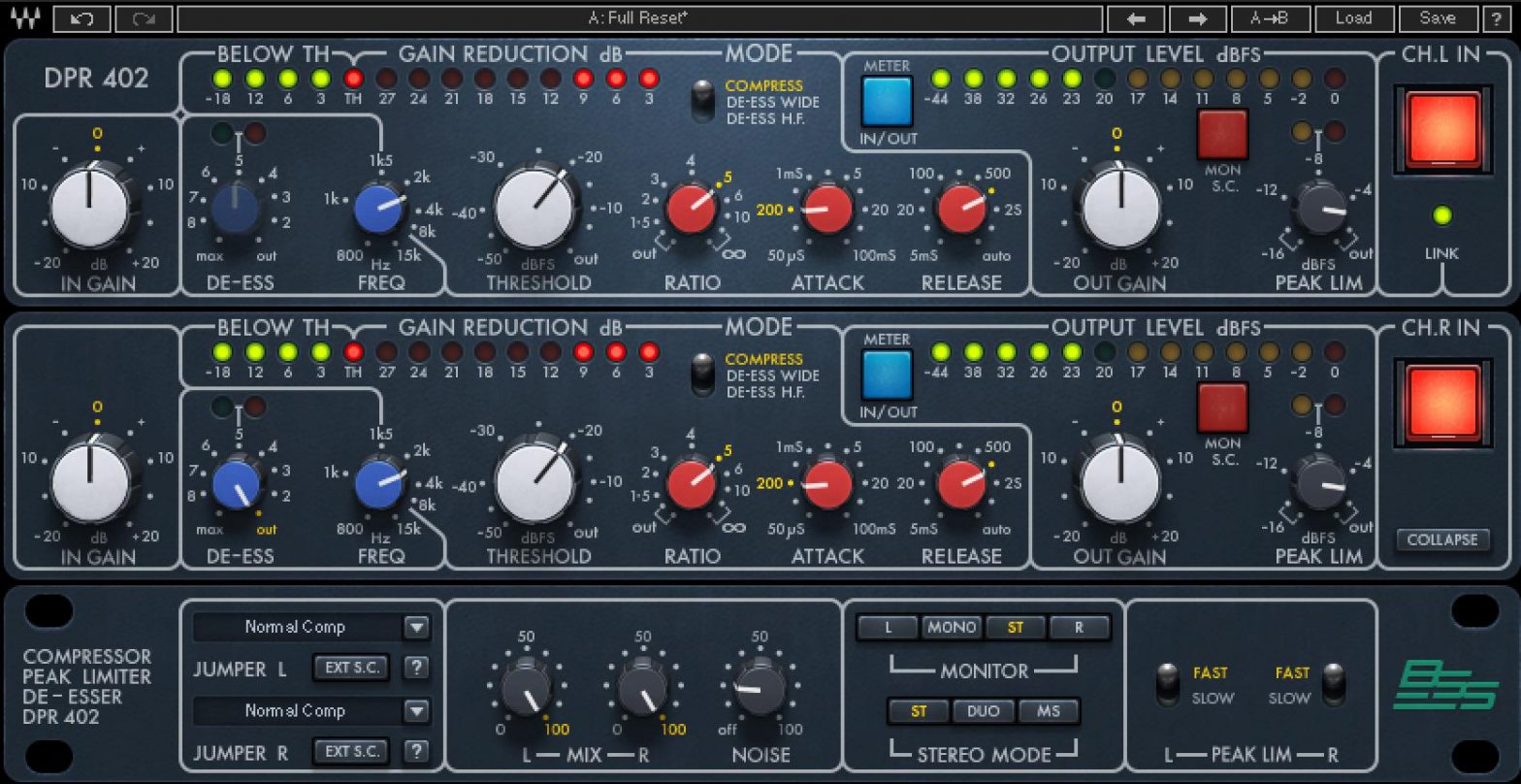
DPR-402The Waves BSS DPR-402 plugin is a software model of the DPR-402 Compressor/Peak Limiter/De-Esser hardware originally manufactured by BSS Audio. This dynamics processor provided the punchy, explosive signature sound for drum machines in the 1980s, and was featured heavily in dance-pop, electronic, and hip-hop music. But it had many other versatile uses in the studio and was also a massively popular favorite on stage.
Working in collaboration with BSS Audio and Harman International, Waves has now modeled this landmark dynamics processor and created a digital tool with the unique sound, functionality and flexibility of the original.
The Original Hardware
BSS DPR-402 was designed in response to the demand for a versatile, compact stereo unit that provides the three most commonly used dynamic functions in a single 1-unit rack space. Its internal architecture, including two independent insert-accessible side chains per channel, allows great flexibility and scope.
A dedicated de-esser control with a variable filter provides wideband sibilance control along with compression and peak limiting. There are three modes of de-essing: full-spectrum attenuation, HF-only attenuation, and a mix of de-essing and compression.The compressor section affords full control over all the normal parameters and offers “auto” time constants for general-purpose use. It can be switched to operate at high frequencies only, resulting in a dynamically controlled tunable HF filter. The control and subtract sidechain insertion points allow for versatile dynamic tonal modification. Gain reduction is achieved using a voltage-controlled attenuator that is capable of reducing the input signal by up to 30 dB.A calibrated peak limiter provides absolute control without compromising the dynamics setting of the compressor. This can yield less dynamic distortion for an equivalent amount of compression.
Features Added to the Plugin
In addition to modeling the above features of the original hardware, Waves has added five features to the plugin for extra flexibility, control, and ease of use:
| 1. INPUT GAIN CONTROL | Controls the input level going into the compressor |
| 2. MIX CONTROL | Controls the balance between the processed and theunprocessed signal. This enables very quick parallelcompression within the plugins. |
| 3. NOISE CONTROL | Adds hardware-modeled noise. |
| 4. MS MATRIX (stereo component only) | Provides separate compression between the mid and sides ofthe stereo signal: Mid is compressed on one channel and sideson the second. |
| 5. MONITOR (stereo component only) | Select the source of the monitor output – Mono, Stereo, Left orRight. (In MS mode, Left monitors the mid while Right monitorsthe sides.) |
Components
WaveShell technology enables Waves processors to be split into smaller plugins, which we call components. A choice of different components for a particular processor allows you to choose the configuration best suited to your material. Waves BSS DPR-402 includes the following components:
- BSS DPR-402 Mono
- BSS DPR-402 Stereo
Chapter 2 – Interface and Controls
Interface
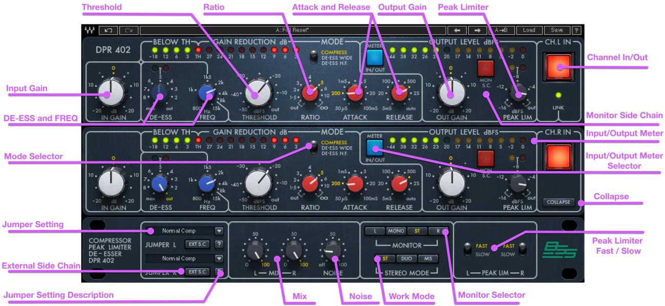
Controls
IN GAINIncreases or decreases the gain of the input signal.Range: -20 dB to 20 dB in 0.1-dB incrementsDefault: 0 dBReset: 0 dBDE-ESSDetermines the amount of de-essing applied to the signal when Mode is set to “Compress.”Range: Out (0 dB) to 9 dB of gain reduction in 0.1-dB incrementsDefault: OutReset: OutFREQDetermines the frequency that will trigger the selected frequency-dependent dynamic processes.Range: 800 Hz to 15 kHz in 0.01-kHz incrementsDefault: 15 kHzReset: 15 kHzDe-Esser MeterIndicates the operation of the de-esser.
- Off – DeEsser not active
- Green – Shows that gain reduction is active, even at low values such as below 1 dB.
- Orange – approximately 15 dB of Gain Reduction
THRESHOLDDetermines the level above which dynamic processes occur.Range: Out (0.0 dB) to -50 dB in 0.1-dB increments.Default: OutReset: Out
RATIODetermines the ratio of compression, expansion or de-essing, depending on the selected Mode and Jumper settings.Range: Out (1:1) to inf:1 in 0.1:1 incrementsDefault: 4:1Reset: Out (1:1)MODEDetermines the function of the dynamic processing operation.
- COMPRESS – Broadband compression
- DE-ESS Wide – Assigns Thresh/Ratio/Attack/Release controls to broadband de-essing.The DE-ESS control is inactive in this mode.
- DE-ESS HF – Assigns Thresh/Ratio/Attack/Release controls to frequency-specific de-essing. De-ess and Peak Limiter controls are inactive in this mode.
ATTACKDetermines the attack time of the compression, expansion, or de-essing, depending on the selected Mode and Jumper settings.Range: 50 µs to 100 ms in 11 predetermined statesDefault: 1 msReset: 50 µsRELEASEDetermines the release time of the compression, expansion or de-essing, depending on the selected Mode and Jumper settings.Range: 5 ms to 4 sec., or Auto for program-dependent Attack and Release times.The ATTACK control is inactive in this mode.Default: 100 msReset: 5 ms
BELOW TH MeterIndicates how far the signal is below the set threshold. When the “TH” LED is illuminated, the threshold has been reached.Range: -18 dB to the threshold.GAIN REDUCTION MeterIndicates the amount of gain reduction applied to the signal.Range -3 dB to -27 dB of gain reductionMETER IN/OUTToggles the meter display between input and output.Range: Input /OutputDefault: OutputReset: OutputOut GainIncreases or decreases the gain of the output signal.Range: -20 dB to 20 dB in 0.1-dB incrementsDefault: 0 dBReset: 0 dBMon S.C.Lets you monitor the sidechain signal that triggers the VCA dynamic process.Range: On/OffDefault: OffReset: OffInput/Output Level MeterIndicates the signal level at the plugin’s input or output, according to the state of the MeterIn/Out button.Range: -44 dB to 0 dBPEAK LIMDetermines the threshold of the Peak Limiter. Peak level limiting occurs after Output Gain, so changing output gain will affect output level, not the peak level. The ratio of the Peak Limiter is fixed at 20:1.Range: Out (0 dB) to -16 dB in 0.1-dB incrementsDefault: OutReset: OutPeak Limiter MeterThis meter indicates when limiting begins (Green) and when heavy limiting occurs (Red).PEAK LIM FAST/SLOWSets the attack and release times of the Peak Limiter. It is generally preferable to use the Fast response setting. However, if this results in audible artifacts, try the Slow response.Range: Fast /SlowDefault: FastReset: FastCH INThis button is an internal bypass button that enables you to quickly bypass all functions of the selected channel in the DPR-402. When the button is illuminated, the channel is active. When the button is off, the channel is bypassed.Range: In (active) / Out (bypass)Default: InReset: InLINK LEDWhen illuminated green, this LED indicates that the two channels are linked together as a stereo pair.
COLLAPSE / EXPANDExposes or hides the bottom panel of the BSS DPR-402 interface. When the plugin loads, the interface is “collapsed” and the button displays “Expand.”Range: Expand / CollapseDefault: CollapsedReset: Collapsed
JUMPER SETTING L/RThis drop-down menu provides a choice of 11 jumper settings modeled from the original BSS DPR-402 hardware unit.Range: 1-11 jumper settings (see section 3.4)Default: 1 (Normal Compression)Reset: 1 (Normal Compression)(?) Jumper Setting DescriptionDisplays a short description of the currently selected jumper setting.EXT S.C.Assigns an external key input to the VCA. This mode must be selected in order for the VCA to “listen” to the external side chain. By driving the control s/c with an external signal, the amplitude of the main signal will be modulated by the envelope of the external control signal.DE-ESS controls, Peak Limiter controls, and Jumper menu are inactive in this mode.Range: On/OffDefault: OffReset: OffMIX L/RControls the balance between the processed and unprocessed signals.Range: 0% to 100% (0.1% increments)Default: 100%Reset: 100%
NOISEControls the amount of modeled noise and hum added to the processed signal.Range: Off to 100Default: OffReset: OffMONITOR (Stereo Component Only)Selects the source of the monitor output.
- Left – Left output is sent to both sides (in MS Mode this monitors the mid).
- Mono – Left and Right outputs are summed to mono and trimmed down by 6 dB.
- Stereo – Stereo mode.
- Right – Right output is sent to both sides (in MS Mode, this monitors the sides).Default: StereoReset: Stereo
STEREO MODE (Stereo Component Only)Selects the stereo processing mode. There are three modes:
- Stereo – All controls are in Link mode. When you set a control on one side (L or R), the other side changes by the same value. Any difference in the settings between sides(created using the Duo or MS mode) are preserved when you move back to Stereo mode.
- Duo – Controls can be set independently for each side, L and R.
- MS – Applies an MS encoding matrix to the input of the plugin, allowing you to separately compress and level the Mid (sum) and Sides (difference) signals. In this mode, the letters M and S will be added at the header of the channels (M at the top left, S at the top right). In MS mode, the left side controls affect the “Mid” signal in the matrix, while the right side controls affect the “Sides” signal in the matrix. Default: Stereo
A note on automation: When you automate settings in Stereo mode, your settings will be saved for the specific channel (L or R) that you have selected, but will affect both L and R. When you automate L and R to different values in Duo mode, you will need to delete your settings for one of the channels (L or R) before you return to Stereo mode in order to avoid conflicting values.
Chapter 3 – Suggested Settings for Initial Setups
The original BSS DPR-402 had no such thing as a “standard setup”; some settings, however, provided a good starting point for certain uses. The original unit, as well as the plugin, has four basic modes of operation. Here are some suggestions for getting started with each.
Compression
The DPR-402 compressor will be very comfortable for anyone familiar with dynamics processors. The following settings provide a good starting point for basic compression.
Initial Settings:MODE SWITCH – CompressTHRESHOLD – OutRATIO – 4:1ATTACK – Irrelevant when RELEASE is set to AutoRELEASE – AutoOUTPUT GAIN – 0 dBCHN IN – In (illuminated)DE-ESS THRSHLD – OutFREQ – When de-esser THRESHOLD is Out, the FREQ is irrelevant.PK LIM THRSHLD – Out
- Rotate the THRESHOLD control counterclockwise until the BELOW THRESHOLD meter is fully illuminated and an appropriate amount of gain is indicated on the GAIN REDUCTION meter. This will result in a drop in output level, as indicated by the OUTPUT METER.
- The output GAIN CONTROL should now be adjusted to reinstate the output level. The levels of the uncompressed input signal and the compressed output signal can now be compared on the output meter by operating the METER INPUT switch.
- Final adjustments of the controls (RATIO, ATTACK, RELEASE, and others) can be made to suit particular requirements. The “Auto” position of the RELEASE control allows program-related operation of the dynamics of the unit, and will be acceptable for most general-purpose applications. In case a tighter or looser result is needed, the ATTACK and RELEASE controls can be set individually.
De-Essing
The DPR-402 has three modes of de-essing available. The choice of mode depends on the source material and the goals of the processing.
De-Essing Wide with Full Dynamic ControlIn this mode, the de-esser detects only high frequencies, using a filter on the sidechain, but it compresses the entire wideband of the signal. Usually, this produces a natural-sounding compression, but it can also result in compressing parts of the signal that are below the set frequency. This may cause unwanted information to be attenuated. Should you encounter undesired effects or artifacts, it is likely that the attack and release settings need to be adjusted.De-Essing HF with Full Dynamic Control In this mode, the de-esser splits the signal into the sibilance part and the non-sibilance part of the audio. The sibilance part is sent to compression while the non-sibilant part is not. After compression, the two parts are summed to recreate the wideband signal with attenuated sibilance. This method provides more control over sibilance compression. This also allows more compression of the sibilant part without changing the other ranges of the signal. However, introducing a filter may create a phase shift, which can result in artifacts when the two signals are summed together.De-Essing Wide with Simultaneous Compression In this mode, the de-esser detects only high frequencies, using a filter on the sidechain, but it compresses the entire wideband of the signal. Usually, this produces a natural-sounding compression, but it can also result in compressing parts of the signal that are below the set frequency. In this mode, the de-esser’s ratio, attack and release are pre-determined.
De-Essing Wide with Full Dynamic Control
Initial Settings:MODE SWITCH – De-Ess WideTHRESHOLD – OutRATIO – InfinityATTACK – 50 µsRELEASE – 100 msOUTPUT GAIN – 0 dBCHN IN – In (illuminated)DE-ESS THRSHLD – OutFREQ – 4 kHzPK LIM THRSHLD – Out
- Rotate the THRESHOLD control counterclockwise until the BELOW THRESHOLD meter is fully illuminated and an appropriate amount of gain reduction is indicated on the GAIN REDUCTION meter.
- Listen to the program and fine-tune the FREQ and THRESHOLD controls to achieve the desired effect. Gain compensation is normally not required when de-essing.
- Although fast attack and release times are most appropriate, they should be adjusted to achieve the best results. The Auto position should NOT be used.
- The source program can be monitored through the internal de-ess filter by clicking the MON SC switch. This replaces the normal signal at the output connector with the output of the de-ess filter and aids in setting the FREQ control in relation to the audible sibilance.If desired, the peak limiter can be used simultaneously with wideband de-essing.
De-Essing Wide with Simultaneous Compression
Initial settings: Set all compressor controls as required. For optimal de-essing effect, do not exceed 10-15 dB of compression. If compression is not required, set THRESHOLD to OUT.Initial Settings:DE-ESS THRSHLD – OutFREQ – 4 kHzPK LIM THRSHLD – Out
- Use the standard controls for compression: THRESHOLD / RATIO / ATTACK / RELEASE. Gradually rotate the DE-ESS THRESHOLD control counterclockwise until the desired de-easing effect is achieved.
- Adjust the FREQ control to ensure that frequencies lower than those causing concern do not trigger de-essing.
- Remember: In this mode, the de-essing is wideband and may cause distortion or pumping effects if the source program contains significant low frequencies.
Peak Limiting
The peak limiter is designed to be used in conjunction with compression and/or any wideband de-essing. It cannot be used simultaneously with HF de-essing.Initial Settings:PEAK LIM THRESHOLD – As requiredPEAK LIM FAST / SLOW – FAST
- If the red LED indicator remains ON other than for occasional peaks, the GAIN control should be lowered in order to reduce the signal going to the peak limiter.
- If this produces an unwanted decrease in overall output level, then the amount of compression should be increased either by reducing the compressor threshold or byincreasing the compressor ratio and then reestablishing the gain.
Additional Jumper Settings
| Num | Setting | Description | Inactive Controls |
| 1 | Normal Com p | Compression occurs equally at all frequencies. | — |
| 2 | HF Re-Emph Comp | Compression is higher at LOW frequencies. This arrangement will make heavily compressed signals sound brighter, compression triggered by low frequencies modulates the high frequencies. This setting removes low frequencies from the side chain, eliminating this unwanted modulation. | — |
| 3 | HF Re-Emph Comp + | Compression is much higher at LOW frequencies. This arrangement will make heavily compressed signals sound brighter as it lessens the effect of heavy low frequencies modulating the treble. | — |
| 4 | LF Re-Emph Comp | Compression is higher at HIGH frequencies. This is useful for controlling harsh or shrill components of a signal, allowing faster ATTACK and DECAY to be used before LF distortion becomes a problem. | — |
| 5 | LF Re-Emph Comp + | Compression is much higher at HIGH frequencies. This is useful for controlling harsh or shrill components of a signal, allowing faster ATTACK and DECAY to be used before LF distortion becomes a problem. | — |
| 6 | Wide LF CNA Comp | This mode compresses the entire audio spectrum based on the frequencies below the setting of the FREQ control. The modulation of HF signals by the LF signals is an effect that may be desired. | — |
| 7 | Narrow LF Cntrl Comp | Only frequencies below that set on the FREQ control are compressed. Low frequencies are compressed without modulating the high frequencies, which pass unattenuated. Normally, the PEAK LIMITER and DE-ESSER should not be used in this mode. | Peak Limiter, De-ESS |
| 8 | Expander Wide | When input signals exceed the set threshold, expansion occurs. Normally, the DE-ESSER should not be used in this mode. The PEAK LIMITER may be used for effect. | De-ESS |
| Num | Setting | Description | InactiveControls |
| 9 | Expander LF Only | When input signals exceed the setthreshold, expansion occurs, but only to those frequencies below that set by the FREQ control. Normally, the DE-ESSER should not normally be used in this mode. The PEAK LIMITER may be used for effect. | DE-ESS |
| 10 | Expander LF Cntrl | Expansion occurs over the entire audio bandwidth. However, it is under the control of either low or high frequencies, as set by the links and FREQ control.Compress | Mode Switch fixed on |
| 11 | Expander HF Cntrl | Expansion occurs over the entire audio bandwidth. However, it is under the control of either low or high frequencies, as set by the FREQ control. | Mode Switch fixed on DE-ESS Wide |
WaveSystem Toolbar
Use the bar at the top of the plugin to save and load presets, compare settings, undo and redo steps, and resize the plugin. To learn more, click the icon at the upper-right corner of the window and open the WaveSystem Guide.
References
[xyz-ips snippet=”download-snippet”]