WAVES CLA-3A Compressor Limiter Plugin User Manual
Chapter 1 Introduction
1.1 Welcome
Thank you for choosing Waves! In order to get the most out of your new Waves plugin, please take a moment to read this user guide.To install software and manage your licenses, you need to have a free Waves account. Sign up at www.waves.com. With a Waves account you can keep track of your products, renew your Waves Update Plan, participate in bonus programs, and keep up to date with other important information.We suggest that you become familiar with the Waves Support pages: www.waves.com/support. There are technical articles about installation, troubleshooting, specifications, and more. Plus, you’ll find company contact information and Waves Support news.
1.2 Product Overview
The CLA-3A is modeled on an acclaimed solid-state compressor originally introduced in 1969. Like its tube-based predecessor, the inspiration for the CLA-3A featured a simple control set, the T4 optical attenuator for gain reduction, and powerful program-dependent compression characteristics. Embraced by engineers and producers the world over due to their unmistakable compression behaviors and unique sonic signatures, the original hardware units are widely used to this day.Chris Lord-Alge considers these among his favorites of all vintage compressors.
About Chris Lord-AlgeGrammy®-winner Chris Lord-Alge is the mixing engineer of choice for pop and rock royalty. Green Day | U2 | Dave Matthews Band | Daughtry | Pink | Leona Lewis | Avril Lavigne | My Chemical Romance | All American Rejects | Nickelback | Rob Thomas | Snow Patrol | Ray LaMontagne | Miley Cyrus | Jonas Bros. | Tim McGraw | Faith Hill | Tina Turner | Rod Stewart | Celine Dion | Santana | Steve Wynwood | James BrownFor almost thirty years, Chris has energized the sound of popular music. His hard-hitting mixes have transformed the radio soundscape, and introduced a new sonic vocabulary along the way. CLA’s massive hardware arsenal includes racks and racks of the most coveted compression units in music history.
Widely known among audio pros and listeners alike for his punchy sound and extreme compression techniques, Chris gave us exclusive access to model his most prized processors, and worked closely with Waves through every phase of development. Together with many of his personal presets, these precision models deliver the distinctive sound of CLA’s favorite classic compressors.
1.3 About the Modeling
Many different elements contribute to the unique sonic behavior of analog gear. Waves painstakingly modeled and incorporated the characteristics of the hardware into the CLA-3A, in order to fully capture and replicate the sound and performance of the original equipment. The hardware was modeled at reference levels of -18 dBFS = +4 dBu, meaning that a signal of -18 dBFS from the DAW to the hardware unit will display a meter reading of 0 VU (+4 dBu).These are some of the most important elements of the CLA-3A’s analog behavior:
- Total Harmonic DistortionPerhaps the most important analog behavior is Total Harmonic Distortion or THD, which is defined as the ratio of the sum of the powers of all harmonic components to the power of the fundamental frequency. THD is usually caused by amplification, and changes signal shape and content by adding odd and even harmonics of the fundamental frequencies, which can change the overall tonal balance. THD can also change peak output gain, usually by no more than +/- 0.2-0.3 db.
- Variable Release TimesIn the original modeled hardware, a T4 optical device determines compression behavior. When strong signals are introduced to the compressor input, release time constants lasting several seconds may result. In certain cases, this may cause the same passage to sound different during successive playbacks, as the Release does not return to the unity position. This behavior is identical to that of the original hardware, and should not be a cause for concern.
- HumWaves modeled both 50Hz power current and 60Hz power current. If you listen closely, you will hear that there is a difference in hum level between 50Hz and 60Hz. Since hum is unique to each region and dependent upon the local electrical conditions, you may find that the modeled hum is different than the hum already present in your studio, and may not be suitable for your particular use.
- T4In the original hardware units, the T4 optical device is responsible for the amount of overall compression and compression characteristics. These components are quite vulnerable to wear and tear, and need to be replaced, ideally, every 2 to 3 years. Depleted T4 devices result in up to 80% less compression as compared to newer components. In the course of our research, we discovered that up to 90% of T4 components in use today have never been replaced. This means that the majority of users are working with devices that compress far below the original manufacturer specifications. If you are used to the performance and behavior of an original unit, and find that the modeled plugin provides more aggressive compression than you are used to, it may be that you have grown accustomed to a worn-out T4 component.
1.4 Components
Wave Shell technology enables us to split Waves processors into smaller plug-ins, which we call components. Having a choice of components for a particular processor gives you the flexibility to choose the configuration best suited to your material. The CLA-3A has two component processors:
CLA-3A Stereo – Two channel compressor, with one detector for both channel pathsCLA-3A Mono – One channel compressor
Chapter 2 Quackster Guide
The CLA-3A offers 2 main controls for compression, as well as additional controls for fine-tuning.
- Using the Compress/Limiter toggle, select Compressor (approximately 3:1 ratio) or Limiter (approximately 100:1 ratio).
- Use the Peak Reduction control to set the amount of compression desired.
- Use the Gain control to adjust make up level after the compression.
- Use the VU Meter to monitor Input, Output, and Gain Reduction levels.
Chapter 3 Interface and Controls
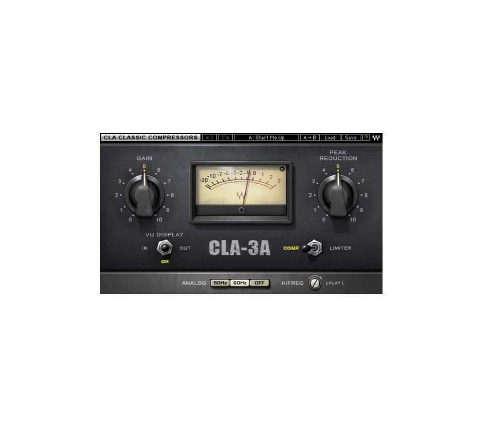
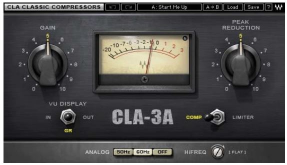
3.1 CLA-3A Interface
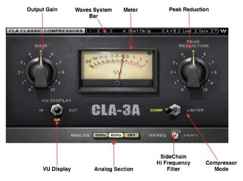
3.2 CLA-3A Controls
Gain controls the output level of the audio path.
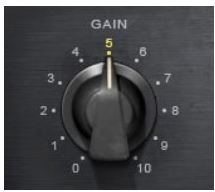 Range: 0 to 10 (in 0.01 steps)Initial Value: 5.50Reset Value: 4.08 (unity gain)
Peak Reduction controls the amount of signal compression.

Range: 0 to10 (in 0.01 steps)Initial Value: 4.00Reset Value: 0
Please note: The scale is not linear and has been adjusted to conform to the exact scaling of the modeled unit. Thus, there may be more compression than expected at certain steps, as with analog gear.
Compressor Mode selects compression or limiting.
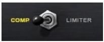 Range: Comp, LimiterDefault: Comp
Hi Freq increases voltage amplifier gain in the peak reduction circuit, for frequencies above1 kHz, leaving lower frequencies unaffected. When set to Flat, the CLA-3A will provide equal reduction to all frequencies. The more you move away from the Flat position, the more sensitive the compressor is to higher frequencies, resulting in heavier compression. This control may also be used as sort of a dresser.
 Range: 0 to 100 (in 0.1 steps)Initial Value: 50.00Reset Value: 100 (flat)
Analog controls analog characteristics caused by noise floor and hum, based on the power supplies of the original units.
 Range: Off, 50Hz, 60HzInitial Value: 60HzReset Value: Off
VU Display toggles between Input, Gain Reduction, and Output monitoring.
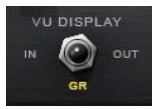
Range In, GR, Out Default GR
3.3 Wave System Toolbar
Use the bar at the top of the plugin to save and load presets, compare settings, undo and redo steps, and resize the plugin. To learn more, click the icon at the upper-right corner of the window and open the Wave System Guide.
Appendix: CLA-3A Controls

References
[xyz-ips snippet=”download-snippet”]