![]() CLA EpicUser Guide
CLA EpicUser Guide
Introduction
Thank you for choosing Waves! In order to get the most out of your new Waves plugin, please take a moment to read this user guide.
To install software and manage your licenses, you need to have a free Waves account. Sign up at www.waves.com. With a Waves account, you can keep track of your products, renew your Waves Update Plan, participate in bonus programs, and keep up to date with important information.We suggest that you become familiar with the Waves Support pages: www.waves.com/support. There are technical articles about installation, troubleshooting, specifications, and more. Plus, you’ll find company contact information and Waves Support news.
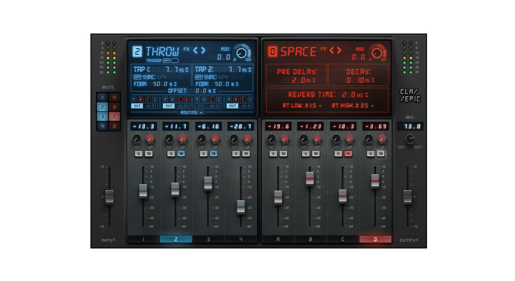
CLA Epic takes tracks and mixes and makes them sound, well, epic. It’s a tool long used by veteran rock music mixer Chris Lord-Alge to create his signature sound. CLA Epic matches four of Chris’s go-to delays with carefully matched reverbs to create sounds that are more impressive and more exciting, with greater depth. Any type of sound, from individual instruments to full mixes, will simply sound better.
CLA Epic’s modules were designed to deliver the sound of Chris’s favorite reverb and delay studio gear, which he uses in various combinations in all of his mixes. Think of CLA Epic as the coupling of a big mid-1980s analog mixing console with a collection of early digital delays and reverbs. Combine up to four very different delays and reverbs and you’ll quickly hear what Epic sounds like.
CLA Epic was designed with legendary mix engineer Chris Lord-Alge (Green Day, Muse, Bruce Springsteen, Keith Urban), who long ago discovered that chaining delays with just the right reverb and then modulating the signal results in Epic tracks.
Quick Start
Epic signal flows from the delays on the left to the reverbs on the right, so it makes sense to start by adjusting at least one delay and then experimenting with the reverbs.
Set Delays
- Click on a delay fader to view its control panel. If you’re familiar with delays, the controls will be quite clear. If not, read the “Controls” section later in this user guide.
- Adjust one or more delays. Before you commit to tweaking the processor that you plan to use, take a quick listen to the other delays. You may find a better starting point.
- Use the fader to set the output level of the delay. Even when a fader is set to zero, the CLA effect is still active.
Route Delay Output
A delay can be sent directly to the output or to any of the reverb inputs.
- Use the A, B, C, and D buttons above each delay fader to route its output to a specific reverb. The Out button routes the delay directly to the plugin output
- When the A, B, C, or D buttons are On, signal processing is in series from the delay to one or more reverbs. When delays A, B, C, or D are not routed to reverb and Out is selected, the delay and reverb are processed in parallel. When the delay is routed to reverb and the output, the processing is both parallel and serial.
- Use the routing faders to adjust the level of each delay send. Each effect has locking mutes and solos. If a delay that is routed to one or more reverbs is muted, the reverbs glow to indicate that they are not receiving signal from the selected delay.Reverb outputs are always routed directly to the plugin’s output.
Adjust Reverbs
- Click on a reverb fader strip to open its control panel. Adjust the reverb as you like.
- Note how the reverb is influenced by the delay or delays that are feeding it. This is where the magic is created.We suggest that you begin by loading a CLA preset from the Load menu. This provides a good starting point for your adjustments and it shows you how best to achieve the CLA sound in different circumstances.
Interface
There are two CLA Epic components: Stereo and Mono-to-Stereo. Their interfaces and functionality are the same, except that the Mono-to-Stereo component has a single mono input meter.
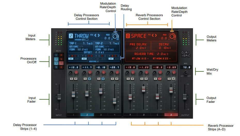
Controls
There are five control sections: input, output, delay processors, reverb processors, and routing. Each delay processor can be assigned to any reverb processor or sent directly to the output mixer. Reverbs are routed directly to the mixer and cannot be sent back to the delay processors.
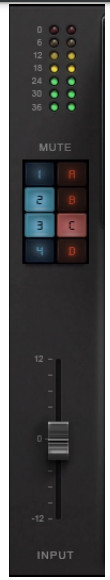 |
The input meter shows the plugin’s input gain, post-fader. |
| The mute panel provides an overview of the mute status of each effect. Any effect can be muted with its own mute button or from the panel. | |
| Input gain is adjusted using the -12 dB to + 12 dB input fader. | |
| Note: if you must adjust the input fader to a very high or very low position in order to attain areasonable gain (as seen on the input meter), you should correct the level sent from the DAW. Thismay be done in the DAW channel or in the plugins that occur earlier than Epic in the signal flow. |
Effect Fader Section
The bottom section is common to all delays and reverbs. Touch a fader to select a processor.
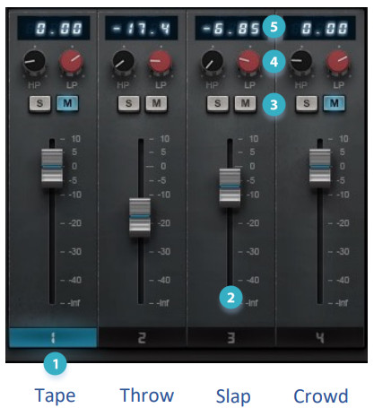
- Effect ID highlights the processor that is currently being controlled.
- Fader adjusts the output gain of the processor (-inf to +10 dB).
- Solo and Mute for each processor. A flashing mute button means that another processor is in solo. A steady mute light indicates that the effect has been muted.
- Hi-pass and Lo-pass filters remove unwanted low and high frequencies at the output of the processor.
- Fader position value shows the position of the fader. Hover over the HP or LP filter control to display its value.
Modulator
The modulator adds motion to the output of the plugin. Used in a subtle manner, it gently adds width to a sound. At more aggressive settings, it creates a distinct warbling effect. The modulation knob controls the two essential aspects of modulation: rate and depth.
RATE is the speed at which the modulator oscillates: the amount of time the effect takes to complete a cycle.DEPTH is the amount of modulation. In other words, depth defines how much the signal moves or changes A single rotary control sets modulation rate and depth for a processor. The outer band is divided into four sections. As you turn the control clockwise, each section yields a greater modulation depth. The modulation rate runs from 0–100 within each section. For example, setting the control marker near the top of the first section will result in low modulation depth with a high rate. When the control marker is in the low part of the highest section, the depth will be high and the rate low.
MODULATOR DISPLAY SETTING
| 1–25 Low depth, rate: 1–100 | 51–75 High-medium depth, rate: 1–100 |
| 26–50 Low-medium depth, rate: 1–100 | 76–100 High depth, rate: 1–100 |
Modulating the taps produces variation in the delay times, which changes the pitch of each tap.
Delay Processors
CLA Epic has four very different delays, each with its own personality. Tape, Throw, and Slap delays are well-known types of processors, whose familiar controls are reflected here. Crowd delay is a bit of a CLA invention—you’ll soon hear how useful it can be.
Tape Delay
The Tape delay is a rich, fat delay effect. It was originally created by taking advantage of the gaps between the record and play heads on analog tape machines to create small, predictable echoes when mixed with the original input. Later, engineers would string between tape machines to create very long delays. It’s thumpy at the beginning and falls off relatively quickly. It has a signature EQ that reflects its tape origins.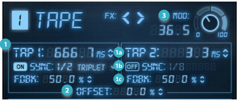
- TAP CONTROLS• DELAY TIME sets Tap delay time manually• SYNC sets the delay time in musical subdivisions• FEEDBACK sets the amount of signal returned to the input
- OFFSET Inversely links Tap 1 and Tap 2 delay time
- MODULATION adjusts depth and speed of modulation
TAP 1 AND TAP 2 DELAY set the length of the tap grid, ranging from 1 ms to 5000 ms. Tap 1 delay is sent to the left channel. Tap 2 goes to the right channel.
SYNC sets the delay time value for each Tap. Epic is always synced with the host. Use the drop-down menu to set musical subdivision. Turn Sync Off to enter delay values that are independent of the host.
OFFSET lets you “pivot” the tap delay settings by up to 20%. If, for example, Tap 1 delay is 100 ms and Tap 2 delay is 200 ms, then increasing Offset to 20% will raise Tap 1 to 120, while lowering Tap 2 to 160. Offset is useful when the tap delays are relatively similar, and the resulting effect feels too monophonic. Pivoting slightly between the two tap values opens up some space.
FEEDBACK controls the amount of output of the delay that is fed back to the input of the processor and is added to the signal. The result is “delays of delays.” Each tap has its own feedback control.
Throw Delay
A Throw delay is similar to a Tape delay, but its tap inputs can be triggered manually or with automation. Use this control when you want to apply a delay to a specific note, word, or sound.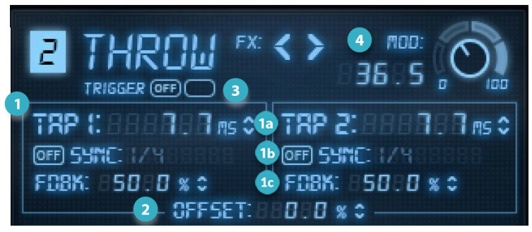
- TAP CONTROLS• DELAY TIME sets Tap delay time manually• SYNC sets the delay time in musical subdivisions• FEEDBACK sets the amount of signal returned to the input
- OFFSET Inversely links Tap 1 and Tap 2 delay time
- TRIGGER ON/OFF Enables manual tap triggering
- MODULATION adjusts depth and speed of modulation
TAP 1 AND TAP 2 DELAY set the length of the tap grid, ranging from 1 ms to 5000 ms. Tap 1 delay is sent to the left channel. Tap 2 goes to the right channel.
SYNC sets the delay time value for each Tap. Epic is always synced with the host. Use the drop-down menu to set musical subdivision. Turn Sync Off to enter delay values that are independent of the host.
OFFSET lets you “pivot” the tap delay settings by up to 20%. If, for example, Tap 1 delay is 100 ms and Tap 2 delay is 200 ms, then increasing the Offset to 20% will raise Tap 1 to 120, while lowering Tap 2 to 160. Offset is useful when the taps are relatively similar, and the resulting effect feels too monophonic. Pivoting slightly between the two tap values opens up some space.
FEEDBACK sets the percent of the tap signal that is returned to the input. The result is “delays of delays.”
TRIGGER lets you manually start and stop the effect. When Trigger is On, clicking the adjacent Trigger button will open the input to the taps— the delay will be fed constantly. Release the Trigger button to close the input and stop the effect. When Trigger is Off, the input signal is always sent to the effect.
Slap Delay
Slap delay is similar to a short reverb, but it doesn’t have a continuous release. A real-world example is shouting in an alleyway between two buildings and hearing one pronounced echo.
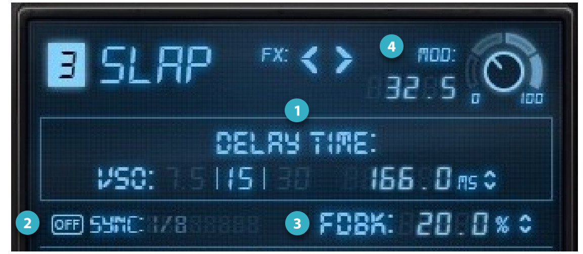
- DELAY TIME: tape emulation (VSO) or manual
- SYNC ON/OFF sets the delay time in musical subdivisions
- FEEDBACK sets the amount of signal returned to the input
- MODULATION adjusts depth and speed of modulation
DELAY TIME sets the delay (in ms) before the onset of the slap. Range: 1 ms to 5000 ms. VSO controls the simulated speed of the tape as it moves between the record and plays heads. This determines the timing of the slap. Delay can be entered at the set speeds (7½ IPS, 15 IPS, and 30 IPS), or manually (in ms).When you select a tape speed (VSO), a corresponding EQ curve is loaded in the background. This speed/EQ curve pair is part of what creates the CLA sound. Adjust the delay manually or turn on Sync to assign musical subdivisions of the host tempo. The EQ curve will not change until a new tape speed is selected.
FEEDBACK controls the percent of the tap signal that is returned to the input. The result is a repeating and diminishing echo.
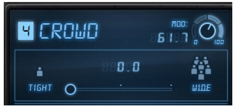
Crowd Delay
The Crowd delay creates a series of increasingly longer delays that diminish overtime to make the source richer and lusher.There is only one control: Tight to Wide. As the control approaches Wide, tap delay time increases. The resulting wide sound is more complex and articulate than a reverb.
Reverb Processors
There are four reverb types, designed to complement the Epic delays.
Plate, Room, and Hall
These are classic reverb effects that have the same controls. Each, however, has its own distinctive EQ curve.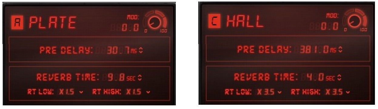
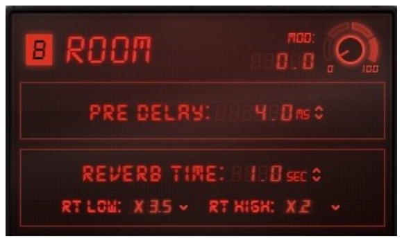 PRE-DELAYPre-delay refers to the amount of time offset there is between the original dry sound and the onset of the reverb tail. Lengthening pre-delay time will retard the beginning of the reverb tail, thus providing a bit more space for a voice or an instrument before the reverb begins. Pre-delay times set too long can result in an unnatural sound. Range: 0 ms to 1000 ms
REVERB TIMEThe Reverberation Time (RT) is the time it takes for the sound pressure to decrease by 60 dB, which is effectively the end of the reverb tail.Range: 0.1 second to 20.0 seconds
RT LOW (LOW-FREQUENCY DAMPING)RT Low controls the decay time of low frequencies in the reverb, relative to the Reverb Time value. Higher settings yield spaces that are warmer and roomier, while lower RT Low settings tend to result in spaces that are more articulate sounding.
RT HIGH (HIGH-FREQUENCY DAMPING)RT Low controls the decay time of high frequencies in the reverb, relative to the Reverb Time value. The higher the setting, the brighter the sound of the Reverb tail.
Space Reverb
The Space Reverb adds a Depth control, which allows you to trim the reverb tail before its defined length.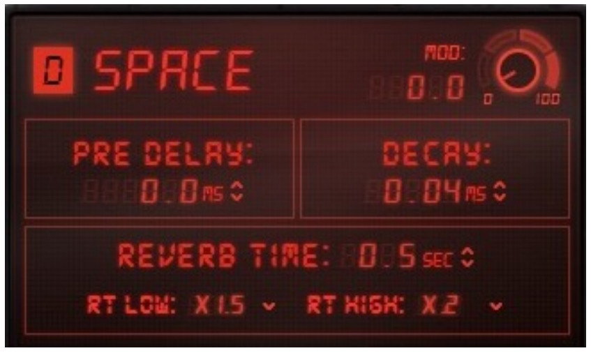
PRE-DELAYPre-delay refers to the amount of time offset there is between the original dry sound (plus the early reflections) and the onset of the reverb tail. Lengthening pre-delay time will retard the beginning of the reverb tail, thus providing a bit more space for a voice or an instrument. Pre-delay times set too long can result in an unnatural sound. Range 0 ms to 1000 ms
DECAYThe Decay control can make the reverb tail behave in a non-linear manner by ending the tail before the Reverb Time setting. At its highest setting (non-linear) the Space reverb behaves like a gated reverb. The Reverb Time must be long enough to be gated (i.e., more than one second). Range: 0.04 to 3.5 (non-linear)
REVERB TIMEThe Reverberation Time (RT) is the time it takes for the sound pressure to decrease by 60 dB, which is effectively the end of the reverb tail. Range: 0.1 second to 20.0 seconds
RT LOW (LOW-FREQUENCY DAMPING)RT Low controls the decay time of low frequencies in the reverb, relative to the Reverb Time value. For example, a “warm” room may have a value slightly above x 1.00; a room with better intelligibility usually has a value below x 1.00.
RT HIGH (HIGH-FREQUENCY DAMPING)RT Low controls the decay time of high frequencies in the reverb, relative to the Reverb Time value. For example, a concert hall might have settings between x 0.25 and x 1.5. The higher the setting, the brighter the sound of the Reverb.
Routing Panel
Each delay output can be routed to any reverb or directly to the plugin output. This makes it easy to create complex delay/reverb combinations.
Routing Panel Main View
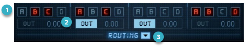
- Delay-to-Reverb sends select
- Direct-to-Output select
- Open the Routing Level Panel
DELAY-TO-REVERB MATRIXEach delay output has five send assignment buttons. This lets you send the output of the delay to any of the four reverbs and the plugin output.In the example above, each delay has its own assignments:
- Tape is sent to Room (B) and Hall (C) reverbs.
- The throw is sent to Plate (A) and Hall (C) reverbs and to the Output.• Slap is sent only to the Output.
- The crowd is sent to Plate (A), Room (B), and Space (D).
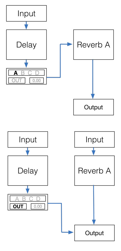
SERIAL PROCESSINGRouting determines whether delay and reverb processing is carried out in series or in parallel. When a delay is sent only to a reverb, that processing is in series. The delay goes straight to the reverb rather than to the plugin output, so reverb processing is directly affected by the delay that precedes it. The delay fader serves as a wet/dry control of the delay signal sent to the reverb input.
PARALLEL PROCESSINGA delay can also be sent directly to the plugin output, rather than to reverb When a delay is sent only to the plugin output, delay processing, and reverb processing are independent of each other, which is parallel processing. The delay fader serves as a wet/dry control of the delay signal sent to the plugin output.
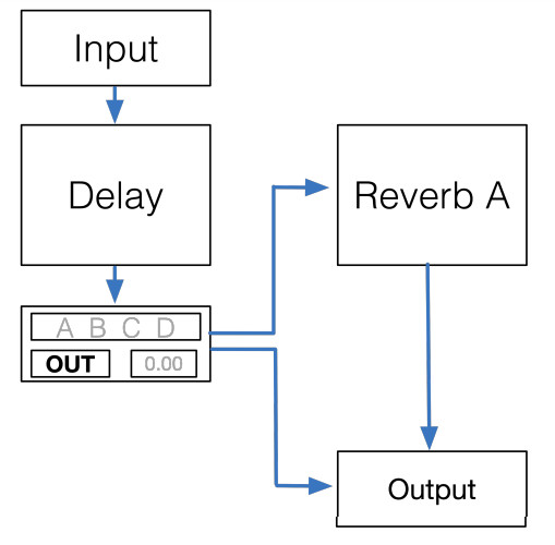 DUAL ROUTINGA delay can be sent to the reverb and the plugin output simultaneously. The delay fader serves as a wet/dry control of the signal sent to the plugin output. The small value box next to the OUT button is used to adjust the level of the signal being sent directly to the plugin output.
If no routing is selected, then the input signal is routed to all delays and all reverb.
Delays can be routed to reverbs and to the plugin output. Reverbs can be routed only to the output; they cannot be routed to the delays, which precede them in the signal flow.
Controlling Delay Send Levels
Click on the Routing arrow to open the Delay sends panel.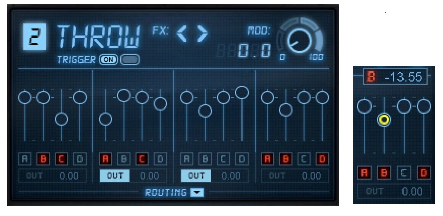
Sends Mute Behavior
When a delay that is patched to one or more reverbs is muted, the mute buttons of the “target” reverbs will flash gray. This indicates that the reverbs are not receiving the expected input,
Output Section
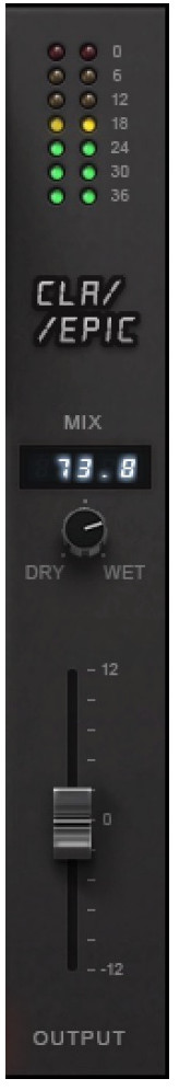
OUTPUT METERSMeter Range: -36 dB to 0 dBContinuous hold clip lights. Click on the meter to clear clip indicators.
WET/DRY MIXControls the mix between the processed path and the wet path. To help achieve Chris’s signature sound, the wet signal is internally down-sampled to 44.1 Hz for processing and then up-sampled to the session sample rate. Range: 0% (dry) to 100% (wet)OUTPUT FADER POSITIONTouch the fader to show its value.
OUTPUT FADERTrims the plugin output level.Range: -12 dB to +12 dB
WaveSystem Toolbar
Use the bar at the top of the plugin to save and load presets, compare settings, undo and redo steps, and resize the plugin. To learn more, click the icon at the upper-right corner of the window and open the WaveSystem Guide.
References
[xyz-ips snippet=”download-snippet”]