![]() WAVESGEQGRAPHIC EQUALIZERUSER GUIDE
WAVESGEQGRAPHIC EQUALIZERUSER GUIDE
Chapter 1 – Introduction
Welcome
Thank you for choosing Waves! In order to get the most out of your new Waves plugin, please take a moment to read this user guide. To install software and manage your licenses, you need to have a free Waves account.Sign up at www.waves.com. With a Waves account, you can keep track of your products, renew your Waves Update Plan, participate in bonus programs, and keep up to date with important information.We suggest that you become familiar with the Waves Support pages: www.waves.com/support. There are technical articles about installation, troubleshooting, specifications,and more. Plus, you’ll find company contact information and Waves Support news.
Product Overview
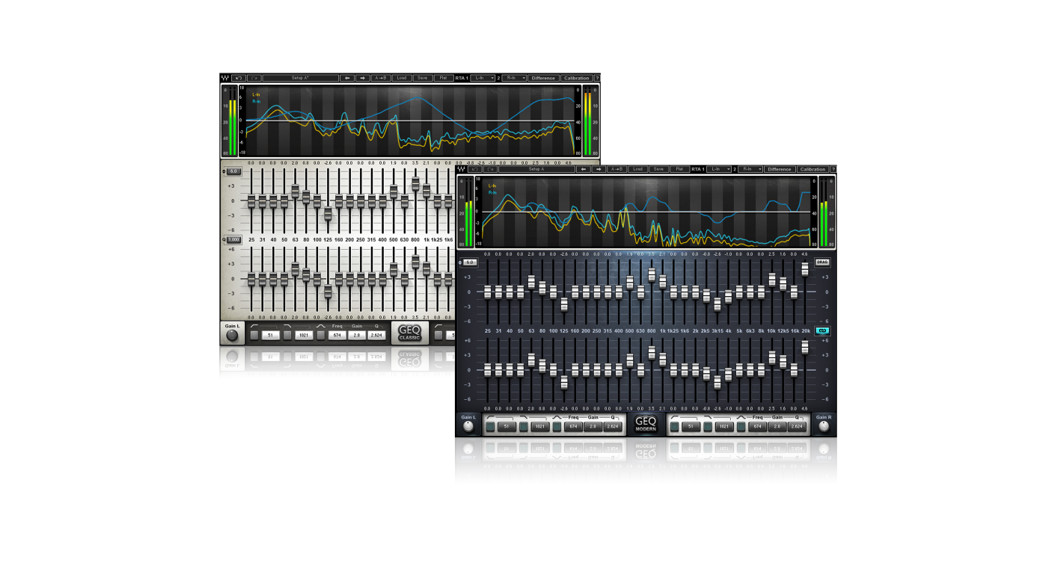
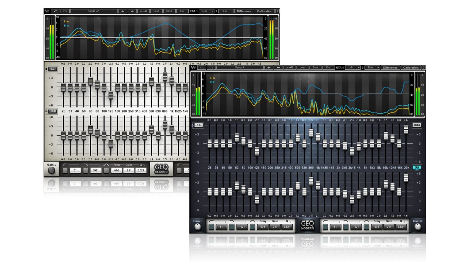
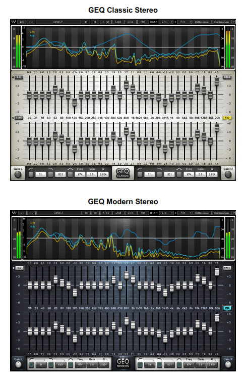
Waves GEQ is a full-featured graphic equalizer with both Classic and Modern mono and stereo components, featuring 30 ISO bands plus high and low pass filters, a high precision floating parametric EQ bell filter, and a real-time analyzer.
GEQ Classic components use traditional proportional Q filters inspired by the renowned DN series 1/3 octave equalizers, which narrow the filter width as you increase a band’s gain; GEQ Modern components utilize special Flat-Top filters which eliminate the artifacts associated with band interaction, and provide perfect plateau and stair-stepped responses. Set band gains one by one, or draw your curve via touch-screen or mouse. Finally, GE Q’s integrated real-time analyzer lets you compare the difference between two sources. Created for live sound but equally useful in the studio as well, GEQ is powerful proof that all equalizers are not created equal.
Concepts and Terminology
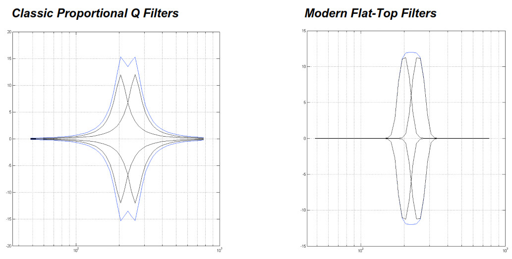
Graphic EQMost graphic equalizers consist of a bank of filters with pre-determined (fixed) cutoff frequencies, typically divided into bands of 1/3 or one octaves each, with frequency cutoffs defined by ISO standards (International Organization for Standardization). It’s common to see them gain controls set as a horizontal array of faders with the lowest frequency on the left and the highest on the right. So if one were to draw a line that plots the gain fader positions at any given time, the resultant line would be a graphical representation of the equalizer’s current frequency response, hence the name “graphic equalizer.”The GEQ offers three bands per octave for a total of 30 bands, similar to the hardware devices commonly used in live sound reinforcement systems. GEQ includes a faders array as well as a parametric graph, plus a real-time analyzer with flexible routing.Proportional QFor its 30 main bands, the GEQ Classic component uses “Proportional Q” filters. The Q value is proportional to the gain adjustment; increasing a band’s gain narrows the filter width.
 Flat-Top FiltersThe GEQ Modern component utilizes special Flat-Top filters which eliminate the artifacts associated with band interaction, and provide perfect plateau and stair-stepped responses. Thus, boosting a set of consecutive bands by 6 dB will result in a 6 dB boost plane, without additional boost due to band interaction.

Band InteractionClose to 0 dB, Proportional Q bells have a fairly wide frequency range. This is not an issue when boosting or cutting frequencies in different ranges; however, when boosting adjacent bands, the two filters will overlap and interact, resulting in unintended gain levels.
Components
WaveShell technology enables us to split Waves processors into smaller plugins, which we call components. Having a choice of components for a particular processor gives youthe flexibility to choose the configuration best suited to your material.GEQ has a total of four components:
- GEQ Classic Mono
- GEQ Classic Stereo
- GEQ Modern Mono
- GEQ Modern Stereo
Chapter 2 – Quick Start Guide
Using the EQ
- Open a mono or stereo GEQ component on a track.
- Select Drag or Draw mode.
- Drag mode: Select individual band faders, move each up or down to set its boost/cut.Draw mode: Select a band fader, move up or down and continuously left or right to draw the EQ curve.
- For further adjustments, use the floating Parametric EQ section to set non-ISO frequency cutoffs.
Setting and Calibrating the Analyzer
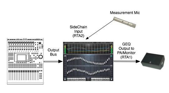
- Open a mono or stereo GEQ component on an output track.
- On the WaveSystem toolbar, go to RTA1 and select a source. (See Section 3.2.)
- On the WaveSystem toolbar, go to RTA2 and select a sidechain input. For example, the sidechain input can receive its signal from a microphone which measures the RTA1 source after passing through the PA system:

- On the WaveSystem toolbar, activate Calibration Mode by clicking Calibration
- Select the RTA Mode: Fast or Slow.
- If required, calculate the delay between the two RTA input sources, and enter the value in milliseconds into the RTA1 Delay field.
- Adjust the RTA1 and RTA2 displayed curve levels using the faders next to the input and output meters. Please note: Adjusting these faders will affect only the analyzer; it will not affect your output.
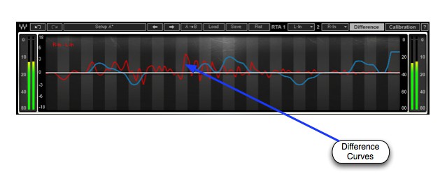
- Press Diff to view the difference in frequency response between RTA1 and RTA2.
- Match the two signals manually using the EQ section of the plugin.
Chapter 3 – Interface and Controls
Interface
Controls
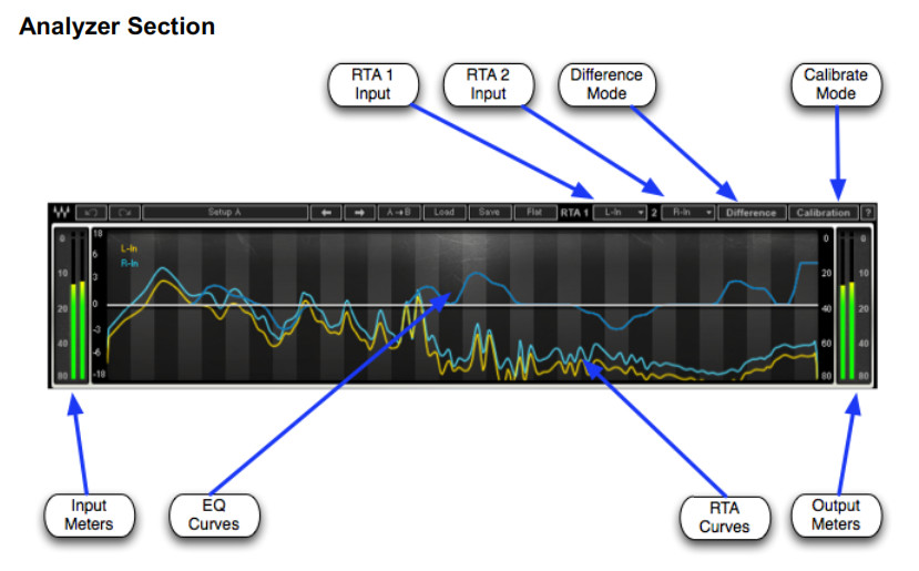
GRAPHIC DISPLAY / ANALYZER shows the EQ curve, RTA1, and RTA2 input RMS frequency responses and the Difference between them.Brown EQ curve on mono components; Left channel EQ curve on stereo components.Blue Right channel EQ curveYellow RTA1 input frequency responseCyan RTA2 input frequency responseRed Difference between RTA1 and RTA2
Frequency Range: 20 – 20,000 HzLevel Range: -80 – 0 dBFSINPUT METER displays input level (peak) in dBFS.Range: -80 – 0 dBFSOUTPUT METER displays output level (peak) in dBFS.Range: -80 – 0 dBFS
RTA1 assigns the first input to the real-time analyzer.RTA2 assigns the second input to the real-time analyzer.Mono Component Range: Off, In, SC-In, OutStereo Component Range: Off, L-In, R-In, LSC-In, RSC-In, L-Out, R-Out, L+RDIFFERENCE mode turns off the real-time analyzer and displays the difference in frequency response between RTA1 and RTA2. This is helpful when you need to:
- Adjust the output signal in relation to the measured post-system response.
- Match the left and right frequency responses.Range: On, Off
Calibration Mode
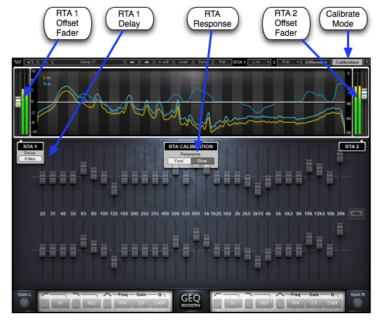
CALIBRATION activates the Calibration mode which calibrates the analyzer.RTA1 & RTA2 FADERS are used to adjust and match the analyzer input levels.RTA CALIBRATION set the response time of the analyzer.Please note: When the Difference is on, the response is Slow, regardless of the RTA Calibration setting.Range: Fast, SlowRTA1 DELAY sets the alignment of RTA1 to RTA2.Range: 0 – 341 milliseconds
Graphic EQ Section
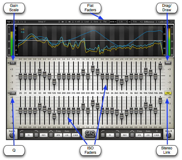
SCALE controls the maximum range of GEQ faders. The scale indicators next to the band faders update according to the selected scale. For example, if the 6 dB scale is selected and 25 Hz is set to +5 dB, changing the scale to 12 dB increases the boost at 25 Hz to +10 dB.Range: 6, 12, 18 dB
Q functions as a multiplier for the proportional Q algorithm. (Classic components only)Range 0.250 – 4.000
ISO FADERS controls the gain of selected frequency centers.Gain Range: -18 to +18 (dependent on Scale settings)Frequency Cutoffs: 25 Hz, 31 Hz, 40 Hz, 50 Hz, 63 Hz, 80 Hz, 100 Hz, 125 Hz, 160 Hz, 200 Hz, 250 Hz, 315 Hz, 400 Hz, 500 Hz, 630 Hz, 800 Hz, 1 kHz, 1.25 kHz, 1.6 kHz, 2 kHz, 2.5 kHz, 3.15 kHz, 4 kHz, 5 kHz, 6.3 kHz, 8 kHz, 10 kHz, 12.5 kHz 16 kHz, 20 kHzDRAG selects the method of setting the band faders.
- Drag mode: Select individual band faders; move each up or down to set its boost/cut.
- Draw mode: Select a band fader; move up or down, left or right, continuously, to draw the EQ curve.
Range: Drag, DrawLINK relatively links left and right channels, including all bands, high and low pass filters, floating Parametric Bell EQ, and Master Gain settings. (Stereo components only)Range: On, OffFLAT snaps all bands to 0 dB.Please note: This does not affect the floating Parametric EQ section.
Floating Parametric EQ Section
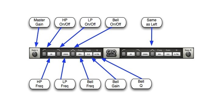
HP activates the high pass filter.Range: On, OffHP FREQUENCY sets the cutoff frequency of the high pass filter.Range: 20 – 990 HzLP activates the low pass filter.Range: On, OffLP FREQUENCY sets the cutoff frequency of the low pass filter.Range: 1000 – 20,000 HzPARAMETRIC BELL activates the floating parametric bell filter.Range: On, OffPARAMETRIC BELL FREQUENCY sets the cutoff frequency of the floating parametricbell filter.Range 20 – 20,000 HzPARAMETRIC BELL GAIN controls the gain of the floating parametric bell filter.Range: +/- 18 dBPARAMETRIC BELL Q determines the width of the floating parametric bell filter.Range: 0.250-50MASTER GAIN controls the output level of the entire plugin.Range: +/- 18 dB
WaveSystem Toolbar
Use the bar at the top of the plugin to save and load presets, compare settings, undo and redo steps, and resize the plugin. To learn more, click the icon at the upper-right corner of the window and open the WaveSystem Guide.
References
[xyz-ips snippet=”download-snippet”]