WAVES Kramer PIE Compressor Plugin User Guide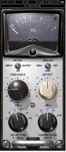
Introduction
Welcome
Thank you for choosing Waves! In order to get the most out of your new Waves plugin, please take a moment to read this user guide.
To install software and manage your licenses, you need to have a free Waves account. Sign up at www.waves.com. With a Waves account you can keep track of your products, renew your Waves Update Plan, participate in bonus programs, and keep up to date with important information.
We suggest that you become familiar with the Waves Support pages: www.waves.com/support. There are technical articles about installation, troubleshooting, specifications, and more. Plus, you’ll find company contact information and Waves Support news.
Product Overview
About the Kramer PIE Compressor
The PIE was modeled on the dynamics processor known as the Pye Compressor, a solid state unit that was manufactured during the 1960s by Pye Telecom. The Cambridge, England-based company originally manufactured military wireless communication devices, later venturing into the television and professional broadcast equipment markets. Pye manufactured a limited number of sound consoles with these compressors built-in, and which were popular enough that the Neve company made a compressor that could fit and replace the Pye compressors in its form factor. While it may well be that the Neve replacements are harder to find than the originals, there is less demand for them than the actual Pye compressors.
As an engineer at London’s Olympic studios during the classic rock era, almost everything Eddie Kramer recorded during that era passed through the Pye compressors.
About the Modeling
Many different elements contribute to the unique sonic behavior of analog gear. Waves painstakingly modeled and incorporated the characteristics of the hardware into the Kramer PIE, in order to fully capture and replicate the sound and performance of the original equipment. The hardware was modeled at reference levels of -18 dBFS = +4 dBu, meaning that a signal of -18 dBFS from the DAW to the hardware unit will display a meter reading of 0 VU (+4 dBu).
These are some of the most important elements of analog behavior:
- Total Harmonic DistortionPerhaps the most important analog behavior is Total Harmonic Distortion or THD, which is defined as the ratio of the sum of the powers of all harmonic components to the power of the fundamental frequency. THD is usually caused by amplification, and changes signal shape and content by adding odd and even harmonics of the fundamental frequencies, which can change the overall tonal balance. THD can also change peak output gain, usually by no more than +/- 0.2-0.3 dB.
- TransformersSome hardware uses transformers to stabilize or change Input/Output loads and signal levels. In earlier days, transformers did not have a flat frequency response, and often introduced low and super-high frequency roll offs. The original channel has transformers which cause high-frequency roll off, so if you encounter loss above 10 kHz, this is due to the modeled transformers.
- HumWaves modeled both 50 Hz power current and 60 Hz power current. If you listen closely, you will hear that there is a difference in hum level between 50 Hz and 60 Hz. Since hum is unique to each region and dependent upon the local electrical conditions, you may find that the modeled hum is different than the hum already present in your studio, and may not be suitable for your particular use.
- NoiseAll analog equipment generates internal noise or a noise floor. In vintage equipment, the noise floor is sometimes quite high and colored. Waves modeled the noise to match the level and color of noise exhibited by the original unit, both with and without signal present.
Components
WaveShell technology enables us to split Waves processors into smaller plug-ins, which we call components. Having a choice of components for a particular processor gives you the flexibility to choose the configuration best suited to your material.
The Kramer PIE Compressor has two component processors:
Kramer PIE Stereo — Two-channel compressor, with one detector for both channel paths
Kramer PIE Mono — One-channel compressor
Quickstart Guide
The Kramer PIE offers 3 main compression controls:
- Use the Threshold control to control the level at which the compressor activates, beginning attenuation. Watch the VU meter needle to determine when attenuation begins, and adjust your settings accordingly.
- Use the Compression Ratio control to set the amount of gain change that will be applied to signal overshooting the threshold.
- Use the Decay Time control to set the speed at which the compressor will return to unity gain when the signal falls below the threshold. Faster decay times will produce louder sound with more harmonic distortion; slower decays will result in a smoother sound with less loudness and distortion.
- Use the Output gain control to set the level that you wish to hear. This will not affect the compression, rather just the output level.
Interface and Controls
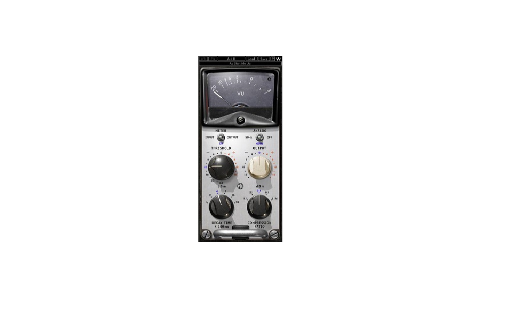
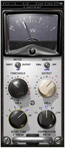
Kramer PIE Interface

Kramer PIE Controls
Threshold sets the gain reference point beyond which compression begins

Range : -24 to +16 dB (in 2 dB steps)Default : +16
Ratio controls the amount of gain reduction for signal above the threshold.
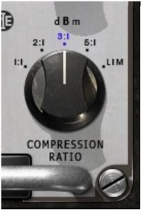
Range : 1:1, 2:1, 3:1, 5:1, LimDefault : 3:1
Decay Time (Release Time) sets the recovery speed of the gain attenuation when the input drops below the threshold.
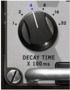
Range : 1, 2, 4, 8, 16, 32 (hundredths of milliseconds)Default : 4
Output sets the output level.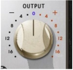
Range : -18 to +18dB.Default : 0
Meter Select toggles between Input, Output, and Gain Reduction metering.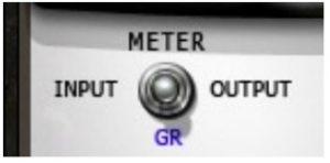
Range : Input, Output, Gain ReductionDefault : Gain Reduction
Analog controls analog characteristics caused by noise floor and hum, based on the power supplies of the original units.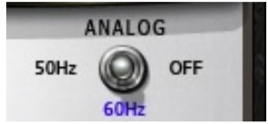
Range : 50 Hz, 60 Hz, OffDefault : 50 Hz
VU Meter displays input or output level in dBVU and gain reduction with smooth analog modeled ballistics. Please note: The PIE Stereo component meter displays the sum of both channels. The same signal fed to both channels will show an increase of 6 dB. If this is problematic, use the VU Calibration function to compensate.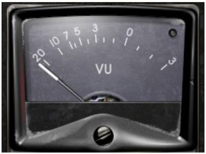
Clip LED lights up when levels exceed 0 dBFS. Click to reset.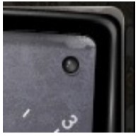
VU Calibrate controls the VU meter headroom calibration.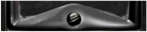
Range24 – 8dBDefault18 dB of headroom (0 dBVU = -18 dBFS)
Please note: The VU Calibration control is represented by the little screw head right below the VU meter display. It does not have a visible label and, for most users, the 18 dB default headroom should be the best choice. However, if you use outboard gear in your studio and your VU meters are calibrated for 14 dB headroom, the PIE allows you to calibrate its VU meter as well.
WaveSystem Toolbar
Use the bar at the top of the plugin to save and load presets, compare settings, undo and redo steps, and resize the plugin. To learn more, click the icon at the upper-right corner of the window and open the WaveSystem Guide.

References
[xyz-ips snippet=”download-snippet”]