![]()
L1 UltramaximizerUser Guide
![]()
Welcome
Thank you for choosing Waves! In order to get the most out of your new Waves plugin, please take a moment to read this user guide.To install software and manage your licenses, you need to have a free Waves account. Sign up at www.waves.com.With a Waves account, you can keep track of your products, renew your Waves Update Plan, participate in bonus programs, and keep up to date with important information.We suggest that you become familiar with the Waves Support pages: www.waves.com/support. There are technical articles about installation, troubleshooting, specifications, and more. Plus, you’ll find company contact information and Waves Support news.
Chapter 1 Introduction
About L1+UltraMaximizerThe Waves L1-Ultramaximizer is a sophisticated audio-processing toolkit that combines an advanced peak limiter, a level maximizer, and a high-performance re-quantizer that’s based on Michael Gerzon’s IDR (Increased Digital Resolution) noise-shaped re-dithering process.UltraMaximizer maximizes both the level of the digital signal and the resolution of the final file, working on “both ends” of the digital word output.
1 IDR™ technology was designed by Michael Gerzon, in collaboration with Waves. Gerzon was a Gold-Medal AES fellow and a world authority in psychoacoustics. He invented the SoundField microphone and was the major contributor to Ambisonics™. The design of IDR is a result of his long-term researches, dating back to 1982, with many of the other leading experts in digital resolution enhancement technologies.
The L1 offers superb re-quantization for all bit depths, including 24-bit, 20-bit, 16-bit, 12-bit, and 8-bit outputs. Its lookahead peak limiter enables the mastering engineer to increase sound file resolution and production master levels with precise control and dithering options.
The Waves IDR™ process brings more choices, greater control, and unmatched compatibility to the mastering environment, whether for a high-resolution CD or low-resolution multimedia. The limiter section of the L1-UltraMaximizer is capable of a very fast, overshoot-free response. Because a typical music signal contains many high-intensity, short-duration peaks, simple normalization of the file may result in a low average signal level.The L1-UltraMaximizer can significantly increase the average signal level of an audio file without introducing audible side effects.UltraMaximizer is designed for mastering, digital editing, multimedia, and any application that requires limiting and/or re-quantization of the digital signal with the highest quality. In order to ensure the maximum possible resolution of a processed signal, it is very highly recommended that the L1 is placed at the end of the processing chain. Failure to observe this will not prevent L1 from working, but you should be aware that the absolute brick wall limiting AND the benefits of IDR re-quantization will be compromised and will need re-limiting to maintain the original level.
What’s NewThis 25 Anniversary edition of L1+UltraMaximizer gives you the same quality sound and flexibility that has set the standard for years. To that we’ve added a few new features.
- A none quantization switch in the IDR section. This turns the quantization process on or off.
- A new Domain setting, True Peak, eliminates inter-sample clipping.
- Automatic Release Control (ARC), which automatically adjusts release time to suit program material.
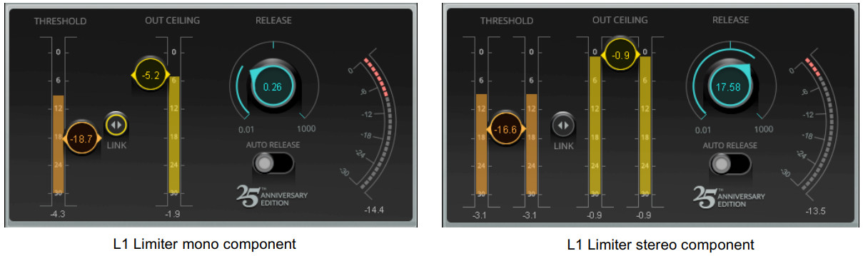
L1 ComponentsOn most host applications and platforms, you can select just the audio processing you need and use only the power necessary to do the job. There are two L1 components:L1 limiter: mono or stereo wideband limiter without IDR.
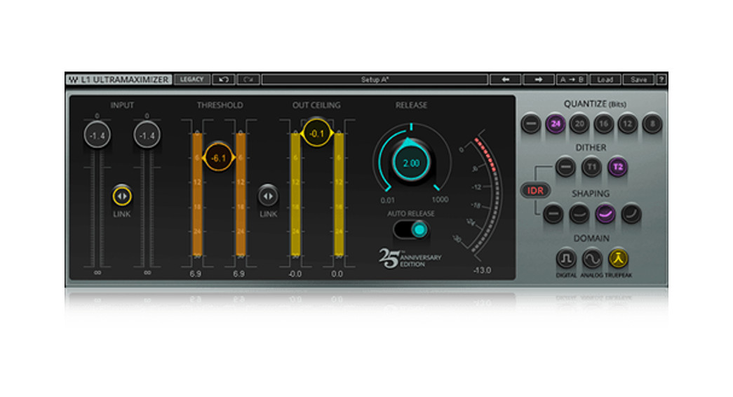
L1+UltraMaximizer (stereo only): the “full” mastering plug-in with limiter and all IDR options.
L1+UltraMaximer stereo component
Interface Options
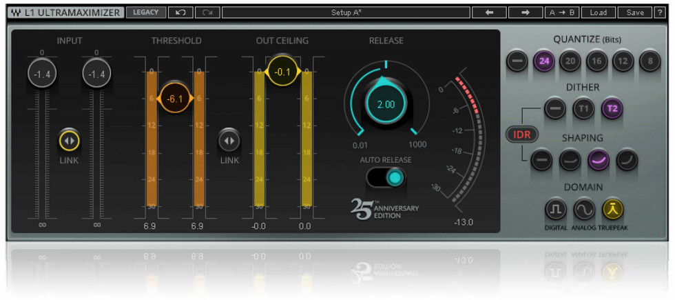
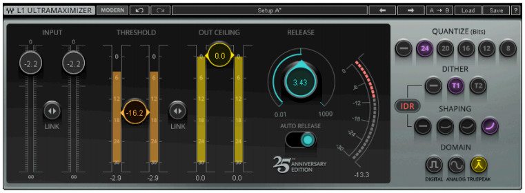
The 25th Anniversary L1 edition provides a new, modern, easy-to-use interface. Its look and functionality are in keeping with other current Waves plugins. We like this new look, but if you prefer you may continue to work with the classic interface. To switch between these two L1 views, click on the Modern/Legacy button on the WaveSystem Toolbar.
L1+UltraMaximizer Modern interface
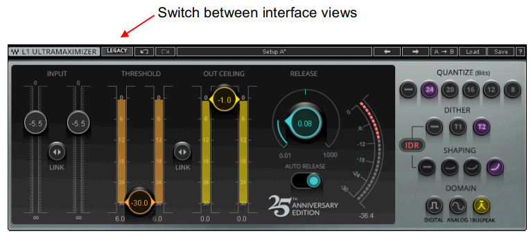
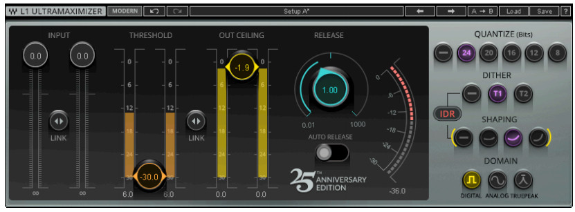
L1+ Legacy interface
Both interfaces offer the same sound quality and workflow.
WaveSystem Toolbar
Use the bar at the top of the plugin to save and load presets, compare settings, undo and redo steps, and resize the plugin. To learn more, click the icon at the upper-right corner of the window and open the WaveSystem Guide.
Chapter 2 Using the L1+UltraMaximizer
L1+UltraMaximizer addresses both level and resolution. As a peak limiter, the L1 component is used to increase the level. It does not quantize, so it can be placed anywhere in the processing chain. But the L1+UltraMaximizer componentquantizes the signal, so it’s particularly important that it is the last process in the path. Depending on which quantization, dither, shaping, and domain choices were made, subsequent processing can cause unwanted artifacts.
Using the Peak Limiter
The Peak Limiter section of the L1 limiter and the L1+UltraMaximizer is the same, except that the L1+ has input faders.
Follow these steps to learn the basics of using the L1 Peak Limiter section:
- Pass audio through the L1 and listen to its output. Set the threshold of the limiter by lowering the Threshold fader.Leave the Out Ceiling setting at its maximum value of 0.0 dB. When using the L1+UltraMaximizer component, you can set the input level using the input fader. When using the L1, adjust the input level in the host DAW.
- When the input signal passes above the threshold, gain reduction is indicated on the meter on the right side. Set the threshold to about 4 dB to 6 dB lower than the peaks in the input meters. You will see 4 dB to 6 dB gain reduction on the gain reduction meter.
- As you reduce the threshold, the output level goes up. Leave the Out Ceiling setting at the maximum value of 0.0 dB. This is your maximum peak output.
- Notice that you have significantly increased the output level. If your threshold is at -12 dB, then you have pushedthe signal up 12 dB (we don’t recommend this!). With the moderate gain reduction, the maximum level of a sound can be significantly increased with minimal audible effect.
- Only the signal above the threshold is limited; all signal below the threshold has a constant gain change that is controlled by the difference between the Threshold and the Out Ceiling. It is this function of the L1 that allows you to maximize the level with the amount of headroom desired.
- Adjust the Release time to suit the application. For most sources, leave the Release time set to 1.0 ms. For mastering set it to between 3 ms and 7 ms. The release time controls how fast the L1 recovers to the constant gain level after a peak is encountered.
- You can select Automatic Release Control, which varies the release based on current content. When Auto The release is On, the release time is adjusted automatically within the range set by the Release setting.
Note: The L1 peak limiter section provides brick wall look-ahead limiting. This, combined with IDR output control, allows for accurate peak control with few audible artifacts. Even though look-ahead processing and True Peak domain settings will effectively prevent inter-sample peaks, we recommend an Output Ceiling setting of between -0.5 dBFS and -0.3 dBFS to leave some headroom for IDR processing and to prevent overshoot.
Using the IDR Section
Increased Digital Resolution dither technology (IDR) is a Waves proprietary noise shaping dither system developed by Michael Gerzon and Waves.It preserves and actually increases the resolution of the digital signal being processed.
You can use IDR throughout subsequent processes, or once at the end of a high-resolution chain. This ensures that the final signal has the maximum resolution possible. IDR is of particular benefit when data is deliberately re-quantized.
L1 features double-precision resolution for more precise calculations.By combining L1’s peak limiting with IDR processing, optimum results may be achieved during final file preparation, mastering and quantization, or re-quantization.Therefore, L1 can maximize the audio level, then increase the perceived resolution of the resulting file.
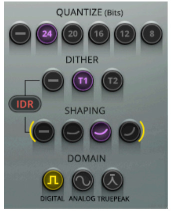
There are three sets of controls in this section:Quantizing Set bit depth for the output signalIDR Select the type of dither and noise shapingDomain Choose a means of controlling the output based on its intended use
Note: Using IDR is by no means a one size fits all process. It all depends on what you start with, what the intended use of the sound file is, and what how the sound will move from digital to analog. The following steps are a good place to start. Additional Useful Material, the last chapter of this user guide, provides extensive background notes that relate to the IDR process and the essentials of quantization, dither, and noise shaping, and analog reproduction of digital audio.We strongly suggest that you refer to this section as you begin to work with IDR.
Basic control of IDRUnder most conditions, work in the sequence described below.
- You should maximize—or at the very least normalize—before you begin dithering and noise shaping a file. This is why the L1 includes both advanced peak controlling and IDR together: one step maximizes both.
- Select Quantize level for the desired output (24-bit, 20-bit, 16-bit, 12-bit, 8- bit, or no IDR).
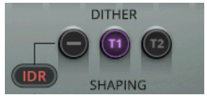
- Select Dither (Type1, Type2, none).
- Select the Type of noise shaping (None, Moderate, Normal, Ultra).
Note: At each step, listen carefully. The differences may be small. To understand how each of these processes works, it’s important to read the following sections: Dither, Noise Shaping, and Domain.
Dither
Dither is a low-level noise applied to a digital audio signal, used to randomize quantization error. Dither smooths the least significant bits of a digital audio word. Dither or re-dither is applied only at the end of a mastering process before the sound file is transferred to its distribution medium.In the L1 there are two types of Increased Digital Resolution dither technology: Type1 and Type2.
Type1 gives no nonlinear distortion.Type2 exhibits a lower dither level.
Dither markedly reduces low-level distortion, but it is (by definition) noise. IDR uses several different processes to obtain good results from dithering while maintaining an acceptable noise floor. The combination of Dither and Shaping settings determine how quantization error and noise will be managed.
Type 1This is the “purist” technology. It’s designed for zero nonlinear distortion or modulation noise at low levels. It combines optimal dither noise with psychoacoustic
noise shaping.
When signals are subjected to several stages of higher-resolution processing and re-quantizing back to lower bit depths, the design of resolution enhancement must satisfy different requirements than a technology designed for on-stage use. If applied several times in succession, a digital resolution enhancement technology optimized for one-stage CD mastering can produce unwanted side-effects.Waves Type1 technology, however, is optimized for use at every processing stage, allowing for the effects of cascading and subsequent signal processing. Type 1 is also optimized to cause minimal side effects when used with stereo signals. Type 1 is the recommended choice for use with 20- and 16-bit file processing and other high-quality mastering applications. By combining level maximization (peak controlling) and IDR processing, 16-bit files created from 20-bit or 24-bit masters this manner can have an apparent resolution of 19 bits—an 18 dB improvement.
Type 2
Type 2 uses dither with a similar noise-shaping curve. But the dither is of a unique kind, designed to minimize the amount of noise added. This gives a lower noise level than the IDR Type1 process, but at the expense of some low-level distortion. Type 2 does have some advantages for high quality mastering as well. It may be used for multimedia applications of all 8-bit/44.1 kHz files and many 8-bit/22 kHz files, depending on source material. Type 2 is “black” with no input signal. That is, there is no dither signal if there is no input. See the 8-bit multimedia mastering chapter for more information.
Bottom lineType 1 has zero nonlinear distortion with somewhat greater dither noise.Type 2 is quieter than Type 1, but may exhibit some low-level distortion.
Quantization ErrorIt’s a good idea to train your ear to know what quantization error sounds like. This way you can understand just what dither actually does. Here’s a simple, exaggerated, test that will illustrate what it sounds like and how Waves IDR and noise-shaping works.
- Use a 16 bit, 44.1kHz sound file and select a region to process. Select the +L1 plug-in in your application and set your system so that you can monitor the L1 output.
- Set Dither Type to None, and Shaping to None. Set Quantize to 8-bit so that will be easy to hear the quantization distortion.
- Listen to the output of the L1 (preview or real-time, depending on your host application).
- To more easily hear the quantization error, reduce the input level at least -30dB until you hear the sound becoming distorted in a “fuzzy” way. If necessary (depending on the input level), pull the Out Ceiling level down to about -15 dB. Leave the Threshold at 0.0 dB. This quantization distortion that you are hearing is present to varying degrees in all digital signals at the 1-bit level.Attention! You will have to raise your monitor levels quite a bit to hear the distortion noise, so do not select BYPASS until you reduce your monitor level.
- Select Normal Shaping. You will hear the music cleanly (the nonlinear distortions are gone), and that a steady hiss in the background is now present. Of course, since you have reduced the input level, this hiss will be much more prominent than in actual work and is exaggerated just like the distortion. You can cycle through the Shaping options to listen to the quantization error-removing effects of IDR’s different noise-shaping filters.
- For our example, leave Dither set to None. Audition the noise-shaping settings to familiarize yourself with the distortion-removing properties of IDR. For 16-bit work, the flexibility of the IDR implementation of L1 gives you the choice of dither and noise shaping. Please read the following sections on Type1, Type2, and Noise Shaping. For specific applications, see the appropriate chapter (8-bit, ³16-bit, etc.).
Noise-Shaping
Another way to decrease the perceived amount of noise and increase perceived resolution is to “shape” the frequency content of the noise so it accommodates the sensitivity curves of human hearing. In basic terms, noise-shaping shifts the energy of the noise to the frequency ranges where we hear it least.
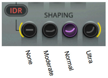
The three options for noise shaping provided in the L1 IDR section push more of the noise energy to higher frequencies (above 15 kHz) where our hearing is least sensitive. This reduces the noise energy of lower frequencies. The three noise-shaping options differ in the amount of this shifting action.Moderate is provided for 8–12 bit files, but also is completely usable for 16-bit files.Normal is the recommended option for use under most conditions for all bit depths.Ultra is a very high-quality setting, suitable only for use at the very last stage of mastering high-resolution files (16-bit and higher) targeted for high-quality digital media. It is theoretically possible that the relatively high amount of high-frequency energy could cause undesirable side effects if the signal is going to be processed or digitally edited again.Therefore, it is best that Ultra is used in the last stage of file preparation. These theoretical side effects might cause clicks at later edit points if Ultra noise shaping had been used, and if played back on poorly designed D/A converters.However, state-of-the-art designs rarely have these troubles. Of course, the effect of noise-shaping is even greater when used with Type1 or Type2 dithering, since noise shaping reduces the audibility of the added dither noise.None applies no noise shaping. Dither produced by Type 1 or Type 2 is unchanged.
Explore the full effects of IDR technology by listening to the same material with both IDR Types and different styles of noise shaping. The most obvious places to examine are notes or reverb during the end of the sound—the “tail.” It is during this time that quantization error is most audible, although it is present on all low-level signals (such as elements that are soft in a mix, etc.). Since the entire issue of dithering is a very subtle one, we recommend you listen to a rather long piece of audio (2–3 minutes) of high quality (20-bits if possible), with a good dynamic range. Jazz and classical recordings are ideal. If you don’t feel you fully understand the trade-offs between IDR and Noise Shaping settings, the option that will generally work well for CD mastering is Type 1 with Normal noise shaping. For minimum noise with 16-bit and greater files, use Type 2 Ultra. For maximum resolution, use Type 1 Ultra.
Domain Options
The Domain section is used to control the maximum output peak levels, based on how the digital audio will be converted to and reproduced in the analog world. L1 offers three Domain options.Digital Peak-limited or normalized signals will not exceed 0 dBFS output. However, it is possible that during digital-analog conversion or reproduction the signal will be raised further, which may result in distortion.Analog Provides a certain amount of inaudible rounding between peaks so that output levels do not distort when transferred to or played on analog systems.True Peak Enables peak limiting on a sub-sample scale. It detects and correspondingly corrects peaks that fall between sampling points.
Chapter 3 L1 Controls and Values
Peak Limiter Section
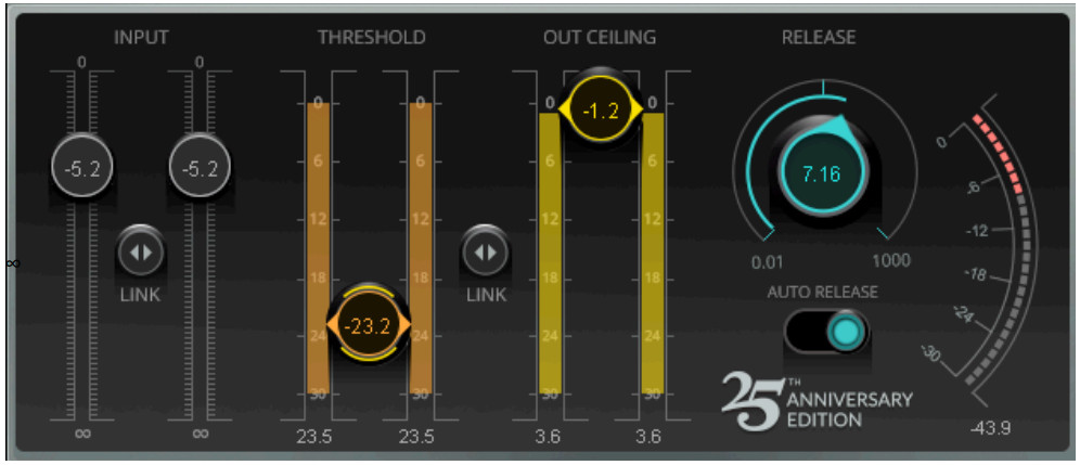
Input FaderControls input level of plugin. Linked or unlinked faders.Range: -infinity – 0 dBFSDefault: 0 dBFS
Input MetersIndependent L/R (stereo component) peak metersRange: -infinity – 0 dBFS
Link ButtonThe Link Button intermittently links the left and right faders of the stereo input. Click+hold on the Link button and slide up or down to move the faders together. Established offsets between the left and right sides will be maintained when the linked faders are moved.
Output CeilingSets the maximum output peak level.Range: -infinity – 0dBFSDefault: 0 dBFS
ReleaseSets the limiter release time. The release Time value is shown on the knob.Range: 0.01ms – 1000 msDefault: 100 ms
Auto ReleaseAuto Release dynamically chooses the optimal release value for a wide-ranging input. It reacts much the way that human hearing expects, and can produce increased RMS level with greater clarity. RMS and peak transients are analyzed and reacted to differently. When Auto Release is On, the release time is adjusted automatically within the range set by the Release setting.Range: On or OffDefault: Off
Gain Reduction MeterRange: -30 dB – 0 dB
IDR Section
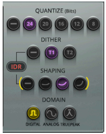
QuantizeThis controls the final bit depth (none, 8-bit, 12-bit, 16-bit, 20-bit, 24-bit) of the L1 output. It is not related to the input bit depth.
16-bitIf you are saving the final output to DAT or CD recorder, then set the Quantize to 16 bit; Waves plugins work at an internal resolution of 24 bits or higher during all processing. The Quantize setting “captures” the best data possible for the selected bit depth.8-bit and 12-bitIf you are saving the final output for low-resolution multimedia sound file work, you should set the output to the appropriate bit depth (8-bit or 12-bit). The file should be sample-rate converted PRIOR TO level maximization and dithering.
20-bitIf you are saving the final output to a 20-bit storage medium, set the Quantize to 20-bit.24-bitThe L1 works at 48-bit resolution and is dithered back to 24-bit when this option is chosen. This is ideal if you have a 24-bit archival medium or intend to have a 24-bit file bounce for later work. In previous versions, the signal was not dithered with this selection. In very old versions of L1, the selection actually indicated “no IDR.”
DitherThis controls the Type of dithering process (Type1, Type2, none).IDR dither Type1 yields lower distortion (greater linearity)IDR dither Type2 yields lower dither level.
Shaping
Select from Moderate, Normal, Ultra, or none. Normal and Ultra are recommended for optimal result with Type1;Moderate and Normal are recommended for optimal results with Type2.Noise shaping may be used without IDR being engaged, although it’s not taking full advantage of the technology. To learn more about IDR processing, read Chapter 4.
Domain
The three Domain options allow you to set the output digital signal based on the subsequent D/A process.Digital When in the Digital Domain position, absolutely no samples will be over the Out Ceiling value. However, during analog conversion, it is possible to have peaks higher than in the digital domain. This is due to very complex digital audio issues involving peaks “between the samples.” Almost all quality-made digital-to-analog converters have at least 3 dB headroom to allow for these peaks; many have at least 12dB headroom.AnalogUse the Analog Domain position when you want absolute control over any peak that occurs in both the analog and digital domains. Some examples (as mentioned previously in this manual) include when:you wish to accommodate poorly designed DACs.the file will undergo further modification, such as ADPCM data reduction.you wish to have a signal that can be broadcast without further peak controlling.In these cases, brick wall limiting is desired in both domains, and you should put L1 in the Analog Domain mode.
True PeakThe True Peak level is a measure of inter-sample peaks that do not register in the sample data but may occur during the reproduction of the digital signal. Now a standard in the broadcasting industry, True Peak limiting oversamples the signal in order to interpolate additional measurement points. With this information, it can provide limiting based on what will actually happen during D-to-A conversion or when converting to a lossy codec.True Peak limiting adds 16 samples of latency to the processing chain.
Chapter 4 Additional Useful Material
L1’s Position in the Signal FlowWe recommend that you use the L1 as the final process after all dynamic and EQ adjustments have been made.Only after these processes are completed should the question of peak level be addressed. Instinctively, it might seem appropriate to normalize the file once all other processing has taken place. But in practice, it may be better to set the peak levels to around 1 dB below clipping using L1.The choice of IDR setting depends on the final use to which the file will be put. Type 1 or 2 with Normal noise shaping is recommended for most work. Type 1 or 2 with Ultra noise shaping is considered best for final mass production of 16-bit and greater masters, and for producing a complete disc master that will undergo no further edits. An example of this would be a production master DAT run off from a hard disk editing system in a single pass, and where no further editing is anticipated (all timing is finalized). However, if the sound file will be subject to editing after mastering, it is recommended to use Normal noise shaping with either Dither Type 1 or Type 2.If you must process or EQ a file that’s previously been processed with L1, you will need to create headroom by lowering the input on later processes, then probably re-limit to restore the average level.The Process of IDR MasteringWaves L1 provides users with three dither options:
- No Dither (none) This is normal truncation and gives a high degree of nonlinear distortion at low levels. This is what most signal processors do.
- IDR Type1 Dither This dither adds a certain amount of noise, causing a 5 dB increase in background noise compared to no dither, but completely eliminates all low-level distortion and signal-dependent modulation effects.The result is a very transparent and clean low-level sound, with very high resolution.
- DR Type 2 Dither This dither adds virtually no audible noise and so is 5 dB quieter than Type 1. It still gives some low-level distortion, however, this distortion is generally much lower than with no dither at all.
There are four noise-shaping options
- None No noise shaping. This results in high audible hiss levels and high distortion levels when used without dither.
- Moderate This typically reduces perceived noise by around 6 dB, and slightly reduces audible distortion when no dither is used.
- Normal This typically reduces perceived noise by around 8.5 dB, and somewhat reduces audible distortion when no dither is used.
- Ultra This gives the greatest perceived noise reduction—typically 10.5 dB.
The noise-shaping options of Waves IDR differ from those in most commercial noise shapers by avoiding shapes of noise that sound “colored” to the ear. While this gives less perceived noise reduction than in some of the most “extreme” shapers on the market, the resulting sound is more pleasant and less colored. The sound file also tolerates several generations of processing.The noise-reduction figures given here apply to sampling rates of 44.1 or 48 kHz. At the lower sampling rates of 22 or 32 kHz, the noise-shaping options are re-optimized for best results at the lower sampling rates and give smaller, but still useful, reductions of perceived noise.
If audibility of noise were the only factor, the choice would almost always be to use Ultra noise shaping. In some situations, however, the Ultra noise-shaping mode may can have disadvantages, and the alternate settings—Normal or Moderate—may prove better.As mentioned previously, it is theoretically possible for any extreme noise shaper to cause trouble with inexpensive DA converters. Therefore, we want to include these small notes below.
When to avoid Ultra noise shaping
- Subsequent digital editing. At the edit points, extreme noise shaping might cause audible clicks. Avoid using Ultra shaping when creating a CD collection of production music or sound effects. These cues would certainly be subject to further digital editing. Use Normal for optimum compatibility.
- Poor Error Correction. When a signal is destined for a carrier medium with poor error correction, or when errors that are not properly corrected occur, the Ultra setting (like all forms of heavy noise shaping and other resolution enhancement technologies) might cause audible background crackles. While these effects generally don’t occur on CD players, they may be noticeable on very cheap products. The amount of such crackles on poor pressings is greatly reduced by Normal noise shaping.
- If a high-gain treble boost is subsequently employed. This can cause the strongly-boosted higher frequencies used by Ultra noise shaping to become so high in a level that they turn out to be unpleasantly or to feed excessive noise energy into loudspeakers. Therefore, Ultra shaping is best avoided in situations where subsequent heavy equalization may be used. A much lower boost of high-frequencies is used with the Normal and Moderate noise shapers. Ultra will not affect Dolby or broadcast encoders.
16-bit and Higher MasteringHere are the basic steps for using L1 in a 16-bit, 44.1 kHz /48 kHz application. These steps also apply to 24-bit and 20- bit mastering.
- All processing, EQ, sample rate conversion, dynamic changes, etc. MUST be done before L1 processing. The L1+UltraMaximizer should be the last processing of the file. Ideally, dithering occurs only once.
- If the left and right channels need to be balanced, adjust the Input levels (separately or together) by using the input faders.
- Using a 16-bit or higher input file, set the Threshold for desired peak limiting. For suggestions on how much limiting to apply for certain applications, see the Specific Applications chapter. In general, set the Threshold to about 4 dB – 6 dB of Gain Reduction in the Attenuation meter.
- Adjust the Output Ceiling up to the maximum peak output you desire. You can take this Output all the way to 0.0 dB without any clipping. For CDs, a recommended setting is -0.3 dB.
- Begin with a Release time of 3–7 ms.
- Set Quantize output for 16-bit (or 24-bit for higher archival or mastering medium if your hardware supports the transfer of 16+ bits).
- Set Dither Type (Type 1 or Type 2). IDR Type 1 is recommended for most high-resolution applications.
- Set Shaping (Moderate, Normal, Ultra, non). Ultra and Normal are recommended for most high-resolution applications.
- Select Digital or Analog Domain mode. Analog domain is recommended for all final production masters, as it gives a little more protection from clipping in poorly-designed DA converters without compromising any L1 processes.For more information see the Digital/Analog Domain paragraph in the IDR Controls chapter.
Suggested Mastering SettingsHere are a few guidelines for using L1. Of course, your preferences will be based on your experiences; the settings here are suggested just for quick reference or as beginning points for your session. The Important IDR Info section contains critical information for you concerning all of the choices in the use of IDR technology. Sample rates would include pulldown, pull-up, and other rates close to those mentioned here.High-resolution mastering (no further digital editing)Setting: Dither Type 1, Ultra, 4 dB to 6 dB gain reduction, default release time.Bit depth: 16-bit, 20-bit, 24-bitSample rates: 48 kHz, 44.1 kHz, 32 kHz.Multimedia and low-resolution masteringSetting: Dither Type none, Moderate/Normal shaping for music, shaping set to none for voice-only; up to 15 dB gain reduction, (this heavy gain reduction may need longer release times, such as 20 ms – 40 ms). Low peak/rms ratio sounds such as synthesizers) should not have very heavy gain reduction with short release times..Bit depth: 8-bit and 12-bit.Sample rates: 22 kHz, 32 kHz, and similar rates.For 11 kHz and belowSet Dither to none and set Shaping to none. Use only the peak limiter with an 8-bit Quantize setting.
IDR Factory PresetsThe Factory Presets (in the Load menu) are relatively self-explanatory. Keep in mind that any combination of dither and noise shaper can be used, but the following settings are particularly recommended for different applications and bit depths:
- General Purpose high-quality use, including material liable to be edited and equalized: Type 1-Normal [24, 20, 16, 12]
- Lowest Noise (CD): Type 2–Ultra [24, 20, 16, 12]
- Low Noise/Highest quality: Type 1–Ultra [24, 20, 16, 12]
- Low Noise while allowing editing/EQ: Type 2–Normal [24, 20, 16, 12, 8; excellent for 8/44.1 files]
- High Quality with the lowest risk of spurious noises on edits or cheap CD players: Type 1–Moderate [24, 20, 16, 12, 8; excellent for 8/44.1 files]
- Low Noise with the lowest risk of spurious noises on edits or cheap CD players: Type 2–Moderate [24, 20, 16, 12, 8; excellent for 8/22kHz files]
- Lowest Noise for Multimedia (ideal for voice): none–none [8; excellent for 8/22 or 8/11 files]
- Lowest Distortion for Multimedia music (good for music or continuous sound): none–Normal [excellent for 8/ 22 files; not for use with 8/11]
Essentials of Digital AudioIn order to make the best use of the L1+UltraMaximizer, it’s important that we explain some of the less obvious implications of digital audio. Once these have been explained, you will understand why Waves thought a product such as L1 was necessary and you will be a in a better position to make use of its powerful features. The operation of the L1 breaks down into two main areas:
- Maximum level of the digital signal through proprietary peak control
- Maximum resolution of the signal through dithering and noise shaping
About Maximum LevelThe maximum level of a digital signal is governed by the highest peak in the file. Simple normalization finds the highest peak, and then raises the entire signal so that this peak is at the maximum value. However, many of these peaks may be of very short duration and can usually be reduced in level by several dBs with minimal audible side effects. Many DAWs, in fact, have tools for redrawing some troublesome peaks by hand. By transparently controlling these peaks, the entirelevel of the file can be raised several decibels more than by simple normalization. This results in a higher average signal level.All limiters require a finite time before full limiting is achieved, so some early transients may not be limited. This is called “overshoot.” The L1+UltraMaximizer avoids overshoot by using a look-ahead technique that allows the system to anticipate and reshape signal peaks with very few audible artifacts. Because there is no possibility of overshoot, L1 can be used with absolute confidence in situations where brick-wall limiting is important.
About maximum resolutionDigital signal processing that alters the original digital data (such as mixing, gain changes, EQ, dynamic processing, etc.) generally increases the number of bits required to represent the signal. Even when processing 16-bit signals, it’s normal to process with 24-bit resolution or more. However, as soon as the resolution is reduced to 16 bits by rounding or truncation (i.e. by removing the bottom eight bits), the resulting rounding error produces an audible distortion at lowsignal levels and a permanent loss of digital resolution. If the audio signal is repeatedly processed and truncated back to16 bits, losses will accumulate, causing a significant loss of fidelity. This is most evident as a loss of the tonal subtleties of low-level sounds within a mix. Human hearing uses this low-level information to construct a mental image of the stereo soundstage, so any compromise in this area manifests itself as a loss of spaciousness and transparency. The Waves IDR prevents this loss of critical low-level detail.The solution is to properly dither and noise shape a signal each time the word length is increased and then reduced (such as nearly every digital signal process requires).Dithering and noise shapingBefore the re-quantization (i.e. reduction of the word length), a precisely controlled amount of noise, called “dither,” is added to the signal. This can convert the low-level nonlinear distortion caused by truncation into a simple steady hiss, thereby removing all traces of low-level non-linearity. The cost of this increased resolution is a slight increase in background noise. Obviously, increased noise levels are not ideal in high-quality audio applications, but fortunately, theperceived level of this dither noise can be greatly reduced by “shaping” the noise in such a way that it falls into an area of the audio spectrum where the human ear is least sensitive.The main point of maximum resolution is simple: to capture the best possible sound quality into a shorter word length (smaller bit depth) from a longer word length (higher resolution).
Digital ClippingThe digital words representing an audio signal have—at each moment—a maximum possible positive value and a minimum possible negative value defined by the bit depth of the file format. Any attempt to force an audio signal beyond these values (by applying excessive gain for example), will result in clipping the audio signal. Clipping distortion generally sounds quite unpleasant and is to be avoided. However, there are other ways in which a signal can become clipped, some of which are far from obvious.
Peak-Normalized SignalsA Normalize process adjusts the peak level of a file so that its peak level reaches but does not exceed digital zero(also called the “clipping point”). This is obviously desirable, as it means that the file is as loud as is possible without the occurrence of clipping. This provides the best signal-to-noise ratio, especially at low bit word lengths.In situations where a higher average sound level is required, L1’s peak limiter allows the typical level of signals to be even further increased by gently pulling down the gain of waveform peaks, without audible nonlinear distortion. L1 can simultaneously rescale the audio data so that the limited peak signals approach—or just reach—digital zero.However, by storing sound files at the maximum possible level, there is a risk that any subsequent processing may take these peak levels too high, resulting in clipping distortion. Peak limiting to 0dB, by whatever means, leaves no margin for any subsequent increase in peak level.Intuitively, you might think that simple gain reduction could be applied without incurring the risk of clipping, and equally that any increase in gain would be sure to cause clipping. This is true. You might also think that applying an EQ boost to any frequency might result in clipping, depending on the peak energy level within the band being equalized. Again, this is true.What is far less obvious is that applying an EQ cut also runs the risk of causing clipping. To prove this would take a lot of math, but the following description should help get the point across.At any instant, the peak level of a signal may be the result of several components at different frequencies and at different phrases relative to each other. Some components will add while others will subtract. But what happens if you filter a frequency that would otherwise be subtracting from the peak level by virtue of its phase? The peak is now higher than it was.For most audio material, this effect will be relatively small—typically increasing peak levels of the order of 0.3 dB. But it is possible that under unfavorable circumstances or with atypical signals, the peak level could increase significantly more than this.An effective peak limiter (like the L1) forces the signal to skim the peak level quite often, so the likelihood of clipping in this way is further increased. In practice, filters attenuating mid- or high-frequency components tend to cause the kind increase in peak level described, but high-pass filters that attenuate the bass can sometimes cause much larger increases of peaks (on the order of several dBs for heavily limited signals). The phase response of certain high- or lowpassfilter types can also increase peak levels by up to 4 dB or thereabouts. Bearing this in mind, it might seem logical to keep the signal peaking a few dBs below digital zero until all processing has been carried out. After that, you can safely normalize the signal. Or can you?A related problem with peak clipping can arise when a normalized sound file or signal is converted to a new sampling rate. The reason is related to the sample-rate conversion process itself. During sample rate reduction, the signal is effectively being filtered and the available audio frequency range is smaller at lower sampling rates. Such filtering can increase peak sound levels in exactly the same way as attenuating equalizers can.Even when increasing the sampling rate, an increase in peak level can occur. This is because the continuous-time audio waveform is represented in the digital domain only by its values at the sampling instants. It is perfectly possible for the peak value of the continuous-time audio waveform to occur at points lying between two sampling instants. Therefore, it is possible for such peak values to be higher than those at any of the sampling instants.When changing the sampling rate, new sampling instants are chosen for the continuous-time audio waveform. These new sampling instants may coincide with an increased peak lying between the original sampling instants. This is particularly likely to occur in signals with a lot of high frequencies since such signal waveforms change more rapidly between the sampling instants.Though artificially contrived signals can be created to really demonstrate this problem, in real life, an attenuation of at least 0.3 dB prior to conversion should provide adequate protection against clipping. You might expect designers of sample-rate converters to consider these possibilities by building in a small amount of attenuation; the cheap ones generally do not. But can you safely normalize a file that you know is at the final sample rate? Unfortunately, not, because many compact disc players (and some other digital consumer equipment) use oversampling digital-to-analog converters (DACs) to produce the analog signal fed to the amplifier. Such oversampling converters involve a sampling rate conversion process which can (and does!) cause audible peak clipping. Once again, some designers appear to have overlooked this problem, although not as widely as they did in earlier DAC designs.
L1 UltraMaximizer / User Guide
References
[xyz-ips snippet=”download-snippet”]