L3-LL Multimaximizer™User Manual
![]()
L3-LL User Manual
![]() Superior Sound Tools
Superior Sound Tools
Chapter 1 – Introduction
1.1 WelcomeThank you for choosing Waves! In order to get the most out of your new Waves plugin, please take a moment to read this user guide.
To install software and manage your licenses, you need to have a free Waves account. Sign up at www.waves.com. With a Waves account, you can keep track of your products, renew your Waves Update Plan, participate in bonus programs, and keep up to date with important information.We suggest that you become familiar with the Waves Support pages: www.waves.com/support. There are technical articles about installation, troubleshooting, specifications, and more. Plus, you’ll find company contact information and Waves Support news.
1.2 Product Overview.
The Waves L3-LL Multimaximizer is a Low Latency 5-band auto-summing peak limiter, the fifth processor in Waves’ acclaimed L-Series of Ultramaximizers and Multimaximizers. With the L3 Multimaximizer, Waves revolutionized the world of mastering. For the first time, producers and engineers could shape their final mixes with unprecedented precision. Now, Waves is proud to present the L3- LL, a multi-band peak limiter that lets you maximize your mix, track by track, instrument by instrument.
Powered by the Waves PLMixer™ Peak Limiting Mixer engine, the L3-LL offers Gain, Priority, and Release controls arranged in a 5 band interface. The L3-LL features a phase-compensated crossover network that splits the signal into 5 adjustable frequency bands while maintaining minimal phase distortion.
The L3-LL uses the same Profiles presets as its predecessor the L3, offering a wide variety of sonic flavors ranging from analog warm to digital cool. Release Characters affect the behavior of the L3-LL’s ARC™ Automatic Release Control across the split-band spectrum.
The L3-LL offers two different plug-in interfaces to control the same essential algorithm.
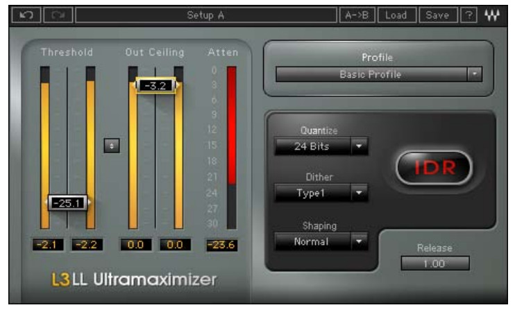
- The L3-LL Ultramaximizer maintains the general control surface of its predecessors the L1 and L2. It adds a Profile selection that controls different internal settings of the multiband engine.
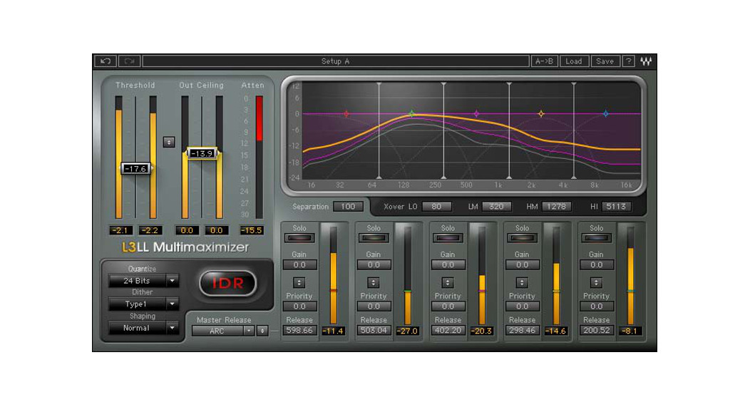
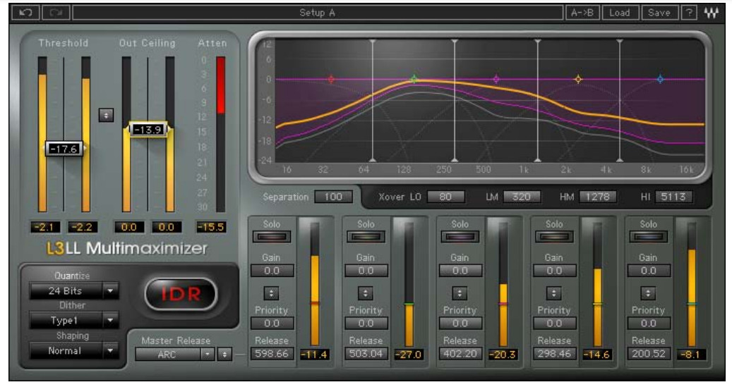
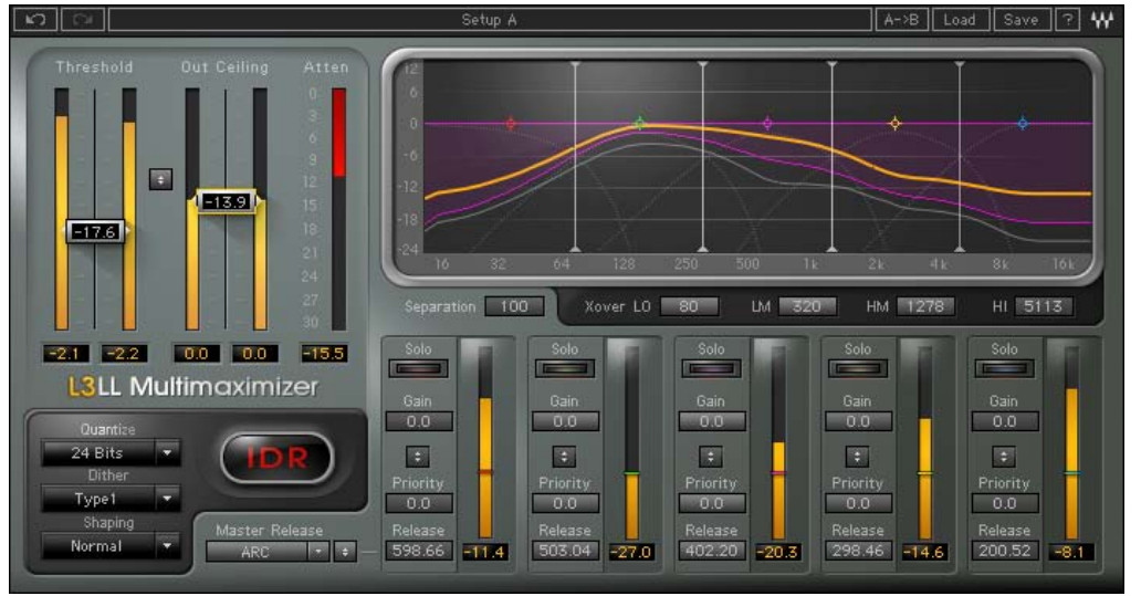
- The L3-LL Multimaximizer allows full parametric control over Gain, Priority, and Release factors for each frequency band, for equalization and fine-tuning. In fact, the L3-LL offers much more than just limiting; it can be used as a fully self-contained mastering chain.
Finally, the L3-LL features Waves IDR™ Increased Digital Resolution double-precision bit quantization and 9th -order noise shaping, for enhanced audio resolution at any setting.
1.3 Concepts and Terminology
The Peak Limiting Mixer™Traditional multiband limiters consist of a given number of limiters operating independently of each other, each set to a particular frequency range. The key to the L3-LL’s power is its patent-pending PLMixer™ Peak Limiting Mixer engine, which uses a single peak limiter to control all of its bands.
Dividing the audio spectrum into 5 bands using phase-compensated crossover filters, the PLMixer™ uses psychoacoustic criteria to intelligently decide how much attenuation to apply to each band, using all available headroom. The PLMixer™ incorporates superimposed Gain and Priority control that allow the user to set gain and priority (relative limiting) across the audio spectrum, functioning like an EQ before the L3-LL’s limiting section. The result is that inter-modulation distortion is minimized and overall loudness is maximized while retaining the simplicity of a single master threshold control.
Unlike traditional multiband limiters, the PLMixer™ does not require a wide-band peak limiter to catch overshoots generated by individual band adjustments; it automatically controls the gain relationship between bands while maintaining brick-wall limiting.
Gain and Priority The L3-LL’s Gain curve and Priority control make for a very powerful mastering tool, enabling both equalization and multiband limiting. The 5-band phase-compensated crossover engine is controlled by 4 frequency cutoff controls.
SeparationThe L3-LL phase-compensated crossover allows control over the amount of Separation between its 5 bands. Separation is similar to a filter cutoff slope (or Q) between the bands’ sidechain being fed to the PLMixer™. At low Separation settings, crossover slopes between bands are moderate, creating more overlap between the bands. At higher Separation settings, the crossover slopes are steeper, resulting in less overlap between the bands.
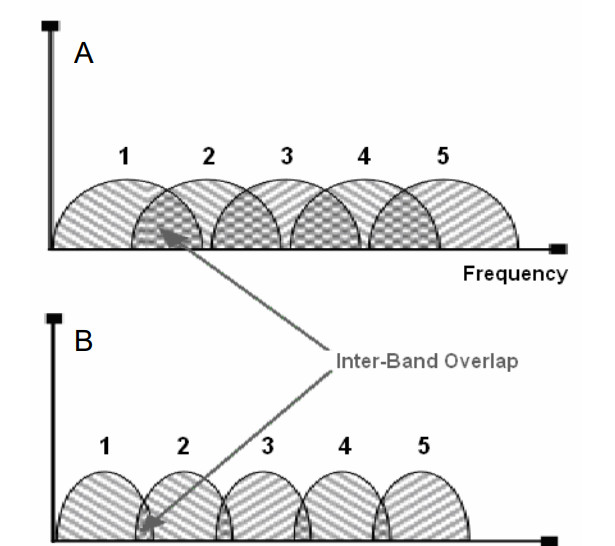
A. Frequency bands’ Side-Chain at low Separation value
B. Frequency bands’ Side-Chain at high Separation value
L3-LL Release BehaviorThe L3-LL offers a wide range of sound qualities which are controlled using the release settings across its frequency bands.
Like its predecessor the L3, the L3-LL’s band release times are determined by Waves ARC™ Auto Release Control, which dynamically chooses the optimal release value for a wide range of inputs. The ARC™ system, like the human ear, analyzes and reacts to RMS and peak transients differently, resulting in increased RMS levels with greater clarity.
While ARC™ is always engaged, the L3-LL Multimaximizer allows independent release controls for each frequency band along with a global Master Release preset control. For example, a Master Release preset could consist of relatively fast release values for the low-frequency bands, with gradually slower release values for the higher frequencies. Accordingly, this character would apply more attenuation to the higher frequency range.
The L3-LL Ultramaximizer has Profiles that contain per band settings for Priority, Release, and Separation, together with a global release control that proportionately shortens or lengthens each band’s release values.
We highly suggest that you experiment with the various Release parameters in order to discover the wide range of sonic flavors the L3-LL can achieve.
1.4 Components
WaveShell technology enables us to split Waves processors into smaller plug-ins, which we call components. Having a choice of components for a particular processor gives you the flexibility to choose a configuration suitable for your material.
The L3-LL has two component processors:L3-LL Multimaximizer Stereo – A stereo channel processor with individual band control.L3-LL Multimaximizer Mono – A mono channel processor with individual band control.L3-LL Ultramaximizer Stereo – A stereo channel processor with global band control.L3-LL Ultramaximizer Mono – A mono channel processor with global band control.
Chapter 2 – Quickstart Guide
We recommend reading this manual to get the most out of the L3-LL. However, for a quick start to your audio, follow these steps:aster located between the Input and Output meters, he Attenuation meter. drag tions. setting up the L3-LL on
- Insert the L3-LL Multimaximizer into your project, preferably as the last processor on the m buss with no subsequent gain adjustment.
- Play your audio, selecting a loop with a high RMS level.
- Select the Threshold/Out Ceiling Link control, and drag downward while watching t
- Once the Attenuation meter registers gain reduction, listen carefully and continue to down until you hear degradation, distortion, or a reduction in level. da
- At this point, stop, and drag upward until the output sound is free of such degra
- Set the Out Ceiling control to -0.2dBfs.
- Set the IDR Quantize factor to match your designated medium.
- Process your audio.
Chapter 3 – Controls and Interface
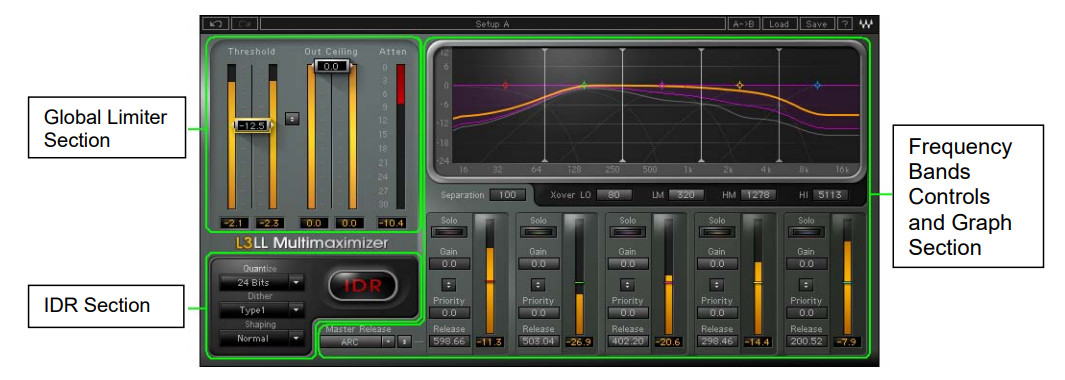
3.1 Global Limiter Section
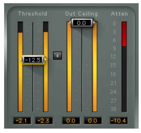 This section consists of controls that globally affect all of the L3-LL’s bands.
Threshold/Input Meter– Range -30dB to 0dB– Default 0dB
The threshold is probably the most important control of the L3-LL, as it sets the global limiting threshold as a reference threshold for the 5 bands. Once set, any signal that goes above the threshold is limited, and gain is automatically made up by the same factor; i.e., if the Threshold is set to -6dB, then automatic makeup gain will accordingly be 6dB.
The Threshold fader is located on the Input Meter, allowing easy adjustment with reference to input energy. Below the Input Meter, you will find Waves standard peak indicators. Click the peak indicator field to reset.
Out Ceiling/Output Meter– Range -30dB to 0dB– Default 0dB
The Out Ceiling fader sets the maximum output level, scaling the output signal to reach the out ceiling value but not exceed it.
The Out Ceiling fader is located on the Output Meter. Below the Output Meter are Waves standard peak indicators. Click the peak indicator field to reset.
Threshold/Out Ceiling Link
The ![]() button lets you adjust the Threshold and the Out Ceiling faders simultaneously, allowing threshold setting changes while monitoring the limiter effect without its makeup gain action.
button lets you adjust the Threshold and the Out Ceiling faders simultaneously, allowing threshold setting changes while monitoring the limiter effect without its makeup gain action.
Attenuation Meter– Range -30dB to 0dB
The Attenuation Meter displays the overall (wideband) attenuation.
Ultramaximizer Profiles
-Range
- Basic Profile
- Extreme Analog
- Semi Separated
- WideBand ARC
- WideBand Manual
- Cosy & Warm
- Loud & Proud
- Lean & Mean
- Low Level Loudness
– DefaultBasic Profile
The Profiles drop-down menu contains factory settings for the L3-LL Ultramaximizer internal frequency bands controls. Each Profile contains per band Priority, Release, and Separation settings, otherwise only available in the L3-Multimaximizer.
Ultramaximizer Release

– Range x0.1 to x10.0– Default x1.0
The Release value is a multiplier for the L3-LLUltramximizer’s internal release time constants, as the selected Profile. It proportionately shortens or length t by hens each band’s release values; lower values result in shorter release times; higher values result in longer release times.
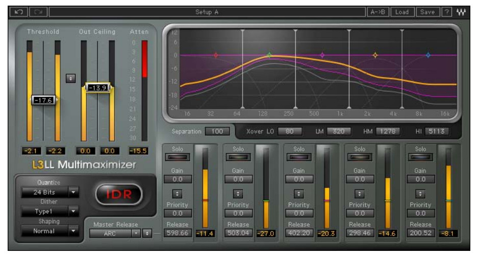
3.2 Graph Display and Controls Section
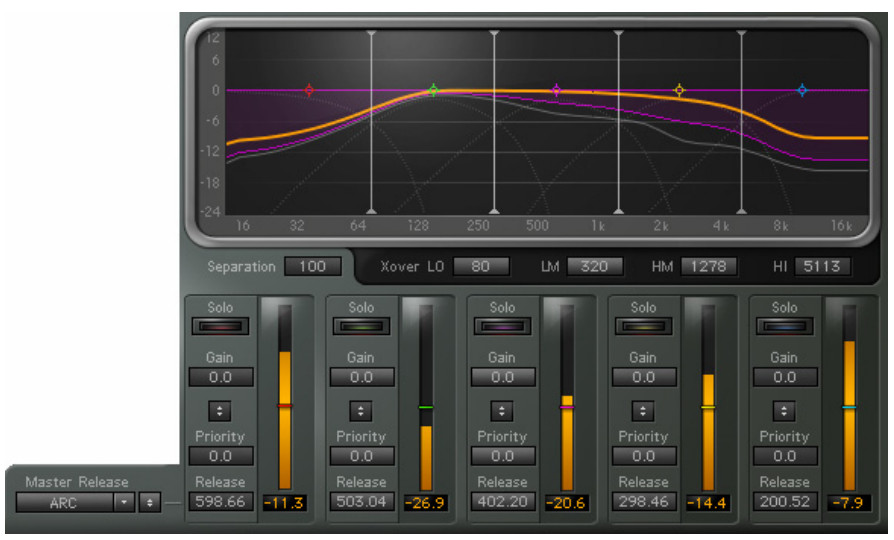
This section consists of the main display and controls for Separation, Xover, Solo, Gain, Priority, Release, and Master Release.
Gain and Priority can be adjusted independently, or together, using the Link control. All parameter settings can be controlled by direct numerical entry into value windows, or by using the graphic display band markers.
To use these controls effectively, you need some understanding of the L3-LL’s internal logic. Like a wideband limiter, the L3-LL applies attenuation only when the threshold is exceeded; unlike a wideband limiter, it does not apply the same amount of attenuation over the whole spectrum. Rather, it applies more attenuation to bands that contain signals with higher peaks. This creates less inter-modulation distortion and retains more detail from the input signal.
Raising a band’s Gain against the limiter’s threshold results in more limiting being applied to that band. Priority allows you to control the amount of limiting applied to each band. Higher Priority results in less limiting (in relation to other bands), while lower Priority results in more limiting. Typically, Gain and Priority controls are adjusted together using the Link control, so that the Priority creates the necessary headroom for Gain to take place. However, it’s important to note that controlling the Gain and Priority separately can actually lead to very interesting and widely diverse sonic results.
Main Display
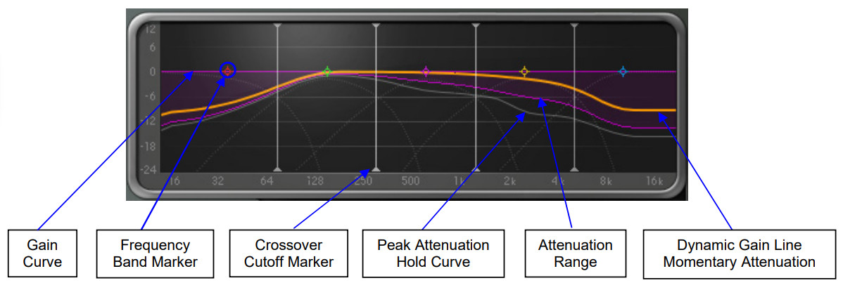
The Gain/Frequency graph displays the peak attenuation across the frequency range.
- The top purple line is the applied Gain curve.
- The orange line is the Dynamic Gain line and shows Gain changes as they happen.
- The semi-transparent purple shade displays a smoothed trail of the Dynamic Gain line.
- The lower gray line is the Dynamic Gain peak hold which displays the maximum attenuation across the frequency spectrum.
The graph also includes 5 markers which, when moved left or right, adjust the bands’ width, and when moved up or down, adjust the linked Gain and Priority.The graph also has 4 line markers that display and allow adjustment of the crossover frequencies.
- Click-vertical drag the band markers changes to gain and priority.
- Click-horizontal drag the band markers change frequency bandwidth.
- Control-click (PC)/Command-click (Mac) and drag constrain movement to the X or Y axis — vertical drag will lock frequency but allow gain change, and horizontal drag will lock gain but allow frequency change.
- Alt-click (PC)/Option-click (Mac) and horizontal drag allow Q adjustment and disables the vertical axis while held.
- Double click on any band marker to toggle in or out.
- Shift-click to select multiple band markers for simultaneous control; shift-click again on any marker you wish to de-select.
Band Controls
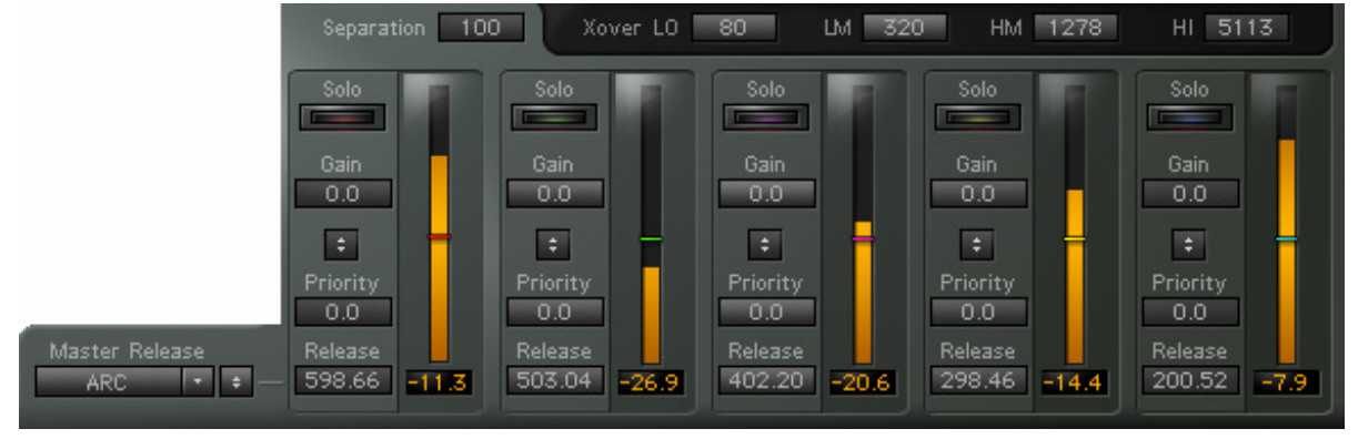
The Band Controls section features controls over the Crossover network which splits the input into Frequency Bands. Each Band has controls for Solo, Gain, Priority, Release, and a Meter displaying the input level.
Separation– Range 0 to 100– Default 100
Separation is similar to a filter cutoff slope (or Q) between the bands’ sidechain being fed to the PLMixerTM. At low Separation settings, crossover slopes between bands are moderate, creating more overlap between the bands. At higher Separation settings, the crossover slopes are steeper, resulting in less overlap between the bands.
Crossover (Xover) ControlsJust below the graph are the Crossover frequency adjustment controls. There are 4 Crossovers in the L3-LL. Each sets the cutoff frequencies for the corresponding High Pass and Low Pass filters.
Each of the four Crossovers has a unique range of frequencies, as follows:
LOW Range: 20Hz to 350Hz. Default to 80Hz.LOW MID Range: 150Hz to 300Hz. Default to 320Hz.HI MID Range: 1000Hz to 5000Hz. Default to 1278Hz.HI Range: 3kHz to 11kHz. Default to 5113Hz.
Per Band SoloSolo the frequency band to adjust the frequency bandwidth. Solo outputs the signal post the crossovers and pre the dynamic process.
Gain– Range -12dB to +12dB– Default 0dB
Gain controls the overall gain of each frequency band. To boost the gain of a given range without over limiting it, raise both Priority and Gain.
Gain/Priority Link
The ![]() button allows simultaneous control of Gain and Priority, retaining a constant offset between them.
button allows simultaneous control of Gain and Priority, retaining a constant offset between them.
Priority– Range -12dB to +12dB– Default 0dB
Priority adjusts the relative limiting, or relative attenuation distribution, across the bands. Raising Priority applies less attenuation to the respective bands (in relation to other bands) while maintaining the same overall limiting; lowering Priority results in more attenuation applied to the respective bands. It’s important to remember that Priority settings are RELATIVE between bands. This means that if all bands are set to the same non-zero priority, it has the same effect as setting all priorities to 0.
Priority Indicators– Range -12dB to +12dB– Default 0dB
The ![]() displays the applied priority for the frequency band.
displays the applied priority for the frequency band.
Per Band Release– Range 0.1 to 2500.
The per band Release sets the reference Release time for each band. This reference be further adjusted by the Master Release Behavior type. release time can
Master Release Link
The  button allows relative release adjustment for all bands.
Master Release– Range ARC, Aggressive, Warm, Scaled, Manual– Default ARC
Waves ARC TM Auto Release Control technology optimizes the actual release time in context with the program. In the L3-LL all Release behavior types use a certain amount of ARC, where some are more adaptive and others less, or the amount of ARC is scaled across the bands in different ways.
ARC — This is the nominal default release behavior type. It is a good overall setting for most material.Warm — Applies more ARC processing to low-frequency bands, less on high frequencies.Scaled — Applies more ARC processing to high-frequency bands, less on low frequencies..Aggressive — Delivers most overall loudness on transient-rich material.Manual — Applies minimal ARC processing. Each band’s release time will correspond to its Release setting.
3.3 IDR™ Section
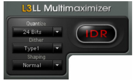
Quantize– Range 24, 22, 20, 18, 16 bit– Default 24
The Quantize control sets the target bit depth of the L3-LL output. Quantize is always active, so the output of the L3-LL will be quantized to a maximum of 24-bits even if you are in a floating-point environment.
Dither– Range Type 1, Type 2, None– Default Type 1
Type 1 is “purist” dithering, designed for no modulation noise at low levels. IDR™ Type 1 is optimized for use at every processing stage, allowing for the effects of cascading and subsequent signal processing. Type 1 is also optimized to generate minimal side effects when used with stereo signals.
Type 2 is designed to minimize the amount of added noise. It delivers a lower noise level than Type 1 at the expense of some low-level distortion. Type2 is “auto-muting” with no input signal is present.
Shaping– Range Normal, Moderate, Ultra, None– Default Normal
The Shaping control selects the type of noise shaping filter that will be applied to the dither and/or quantization noise. Noise shaping transfers the noise energy toward the higher, less audible range of the frequency spectrum. Selecting None leaves the noise unfiltered.
IDR Active Indicator

Whenever Dither or Noise Shaping are engaged, the IDR status indicator will be colored red to indicate activity in the IDR section. When both Type and Shaping are set to None, the IDR logo will turn gray to indicate that IDR is disengaged. The output is still rounded according to the Quantize bit depth chosen.
3.4 WaveSystem ToolbarUse the bar at the top of the plugin to save and load presets, compare settings, undo and redo steps, and resize the plugin. To learn more, click the icon at the upper-right corner of the window and open the WaveSystem Guide.
Appendix A – Controls List
| Control | Range | Default |
| Threshold/Input Meter | -30dB to 0dB | 0dB |
| Out Ceiling/Output Meter | -30dB to 0dB | 0dB |
| Attenuation Meter | -30dB to 0dB | |
| Master Release | ARC, Aggressive, Warm, Scaled, Manual | ARC |
| Release | 0.1ms to 2500ms | 598ms, 503ms, 402ms, 298ms, 200ms |
| Priority | -12dB to +12dB | 0dB |
| Gain | -12dB to +12dB | 0dB |
| Xover | LO = 20Hz to 350Hz LM = 150Hz to 3000Hz HM = 1000Hz to 5000Hz HI = 3000Hz to 1100Hz | LO = 80Hz LM = 320Hz HM = 1278Hz HI = 5113Hz |
| Separation | 0 to 100 | 100 |
| Quantize | 24, 22, 20, 18, 16 bit | 24bit |
| Dither | Type 1, Type 2, None | Type 1 |
| Shaping | Normal, Moderate, Ultra, None | Normal |
| Ultramaximizer Profiles | Basic Profile Extreme Analog Semi Separated WideBand ARC WideBand Manual Warm & Cosy Loud & Proud Lean & Mean Low-Level Loudness | Basic Profile |
| Ultramaximizer Release | x0.1 to x10.0 | x1.0 |
Appendix B – IDR™ In Depth
Dithering and Noise ShapingDithering and Noise Shaping are two independent, complementary techniques that improve the perceived quality of digital audio after it has been re-quantized. Each technique is responsible for the improvement of a different subjective quality of the noise caused by re-quantization.
Dithering alters the character of the quantization noise to more closely resembling analog hiss, rather than digital quantization noise. The main effect of dithering is to reduce or eliminate all correlations between the quantization noise and the original signal, thus minimizing the non-linear distortion effects typical of digital quantization noise. The dithering process replaces the non-linear distortion sound with steadier, less displeasing analog-hiss type noise.
Noise Shaping psycho-acoustically optimizes the distribution of overall noise energy across the spectrum, by taking into account the frequency ranges to which the ear is most sensitive. Noise Shaping decreases noise level in the 1-6 kHz range, a range to which the ear is sensitive while increasing noise level in the frequency range above 15 kHz to which the ear is less sensitive.
In short, dithering and noise shaping work by modifying the character and frequency content of noise, making it less displeasing to our ears.Here’s how Dithering and Noise Shaping help maintain 3 more bits of detail: Our brains are capable of perceiving details that are lower than the noise floor. Since quantization noise is correlated to the signal, it effectively masks the signal. Dithering breaks this correlation by inserting random signals, allowing our brain to distinguish signal from noise and thus perceive low-level details. Noise shaping adds even more detail by shifting noise to a less audible range, away from the desired signal.
IDR™ Dither Options
Type 1 is a wide-band dither. Type1 adds a certain amount of noise, causing a 5dB increase in background noise. It completely eliminates low-level distortion and signal-dependent modulation effects. The result is a very transparent and clean low-level sound with a high resolution. It most resembles the steady low-level hiss of an excellent quality analog system with no digital quantization noise.
Type1 delivers no nonlinear distortion or modulation noise at low levels and generates minimal side effects when used with stereo signals. It is the recommended choice for high-quality mastering applications. By combining level maximization and IDR Tm processing, 16-bit audio created from 20 or 24-bit masters have an apparent resolution of 19 bits. This is an improvement of more than 18dB. Finally, unlike other dithering engines that are designed for single-stage CD mastering, IDRTM Type 1 is optimized for use at every processing stage, allowing for subsequent signal processing.
Type2Type 2 is a narrow-band dither that adds a minimal amount of noise. It delivers a noise level about 5dB lower than Type 1, while adding some low-level distortion. (The distortion level is lower than when no dithering is applied.)
IDR Noise Shaping OptionsAs explained above, noise shaping shifts the noise to the frequency ranges where we hear it the least. The three Noise Shaping options provided by the IDRTM system differ in the amount of this shifting. IDRTM features a ninth-order Noise Shaping filter for optimal sound quality.
ModerateThis setting typically reduces perceived hiss (or distortion, if dither is not used) by around 6dB. The added high-frequency noise is about 9dB at a 44.1 kHz sampling rate.
Here are some recommended IDR™ settings:
- For CD-mastering, Type 1 dithering with Normal noise shaping
- For minimum noise, Type2 dithering with Ultra noise shaping
- For maximum resolution, Type1 dithering with Ultra noise shaping
References
[xyz-ips snippet=”download-snippet”]