WAVES L360 UltraMaximizer Software Audio Processor User Guide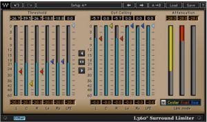
Introduction and Overview
Thank you for choosing Waves! In order to get the most out of your new Waves plugin, please take a moment to read this user guide. To install software and manage your licenses, you need to have a free Waves account. Sign up at www.waves.com. With a Waves account you can keep track of your products, renew your Waves Update Plan, participate in bonus programs, and keep up to date with important information.
We suggest that you become familiar with the Waves Support pages: www.waves.com/support. There are technical articles about installation, troubleshooting, specifications, and more. Plus, you’ll find company contact information and Waves Support news.
Introducing Waves L360°, a Surround Peak Limiter and Level Maximizer for 5 or 5.1 channels . This tool is based on the legacy of its Mono and Stereo predecessors – Waves L1 and L2 UltraMaximizers. It provides Brick Wall Peak Limiting and the Waves IDR 360° Increased Digital Resolution plug-in with Dithering and Noise Shaping for multi-channel digital audio.
L360° supports operation at sample rates up to 96kHz.
BRIEF OVERVIEW
L360°’s Peak Limiter has a look-ahead mechanism to anticipate upcoming peaks and start pre-attenuating to achieve absolute brickwall peak limiting with maximum transparency. It also incorporates Waves ARC – Auto Release Control. This technology sets the optimum program sensitive release time for the applied gain attenuation.
The L360° allows linked dynamics processing for preserving the cross channel balance and phantom directions. It allows flexible link modes to fit right in with the preferred grouping scheme that you wish to follow, or the one you think sounds best. This is done on a single 5 or 5.1 Insert without the need to split to multiple stereo and mono groups. You get all the options on the same multichannel insert.
HOW DOES L360° WORK?
The level maximization is gained by specifying a peak threshold and adding the gain of the threshold to the output. The threshold, being a point that’s not to be exceeded, creates headroom that is automatically made-up. For example, if the threshold is at –6dB, then no audio will exceed –6dB, creating 6dB of headroom. The output will then be boosted by 6dB to make up for the 6dB headroom,boosting the whole signal by 6dB.
L360°’s 48-bit double-precision process maximizes resolution so that no bits are lost in the Peak Limiting process. The dither eliminates further quantization noise by adding some very low-level rapid noise completely de-correlated from the program. The dither forces quantization noise to become part of this rapid low level noise. As a result, instead of correlated distortion noise we get something that’s more like tape hiss, but at an extremely low level.
WHEN TO USE L360°.
L360° is recommended for use in the last step of processing a 5.1 surround mix. The best place to insert L360° is just after the final output master fader, preferably with no gain stage after it.
Classic use for L360° would be when Mastering ready-mixed 5.1 audio to its designated format before it is transferred or encoded to its target medium, whether it’s a movie soundtrack, or multi-channel music designated to play back on common Home Theater systems or any 5.1 Surround Sound system.
L360° can also be useful when you have low amplitude 5.1 material which needs to be boosted in the mix. This will work better than normalizing, because the original peak value will not serve as a denominator. You will specify the peak value with the ceiling control providing optimal gain adjustment control. Multiple runs of dithering will boost dither noise further. That’s the reason why, when applied last, this noise is extremely low in level but it is sufficient to mask preexisting quantization noise and eliminate new quantization noise effectively.
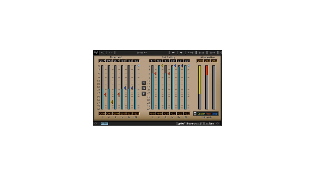
L360° PLUG-IN COMPONENTS.
The L360° UltraMaximizer consists of components for 5 or 5.1 (6) Channel Inserts. When working on a surround mix in a DAW environment, the L360° should be listed in the insert menus of any 5 or 5.1 tracks, auxiliary inputs and master fader tracks.
LINKED FUNCTION OF L360°.
L360° supports flexible and versatile linked functionality. Parameter linking is easily carried out by using global threshold and ceiling controls and Dynamic process linking is subject to a user-selected Link Mode where certain channels are linked to a common sidechain.
Parameter linking is important for the general settings. In this case, the user can use a master threshold or master ceiling control to specify the same threshold or ceiling value to all audio channels assuring a common general makeup or level maximization value. For example, specifying a common –6dB threshold and a 0dB ceiling to all channels will result in a general uniform 6dB boost.
Another type of link can be described as linked dynamics processing. In this case, we link several channels to a common process sidechain. All of the channels linked to a common sidechain will get the same gain attenuation when the level of any of them exceeds the specified threshold. This type of link is critical for the preservation of the cross channel balance and direction of phantom images. For example in a stereo image if we apply different attenuation to the Left and Right channels, then the Stereo image symmetry is distorted. The L360° offers up to 3 sidechains, which are equal to 3 stereo limiters. The Dynamics process link is user selected in the Link Mode control right under the 3 attenuation meters and a straightforward color code helps you keep track of which channels are linked to which sidechain.
For a detailed description of the dynamic process link modes, see Chapter 3 – Link Modes in L360°.
WAVESYSTEM TOOLBAR
Use the bar at the top of the plugin to save and load presets, compare settings, undo and redo steps, and resize the plugin. To learn more, click the icon at the upper-right corner of the window and open the WaveSystem Guide.
Using L-360°
L-360° has two main sections –
- Threshold: Sets the point above which no peaks shall pass. For example, if you set the threshold to –6dB and you have a passage where the peak is at –3dB, the L360° will attenuate the signal by 3dB and the signal passing through will not exceed the threshold. In other words the 3dB peak will be limited to reach only –6dB.
- Ceiling: Sets the output’s peak value so that the peak limiter threshold will reach this value in the output. In relation to the above example, if the ceiling is 0dB (or full scale), the output will be 6dB louder than the input.
When using the Threshold control, the most audible effect is the increase in gain. Indeed, the gain increase is important, but it is far more audible than the more subtle effect of the dynamics process and the gain attenuation. To be able to hear the sound characteristics at the same general level we recommend moving the Ceiling along with the Threshold. If the Ceiling or output peak value is equivalent to the Threshold, then the gain increase is eliminated, allowing us to hear only the effect of the limiting on the audio material. After you achieve the desired sound, adjust the ceiling back to the desired peak output value and gain level.
BASIC OPERATION
The following section will guide you through the basic operation routine that will always give you good, professional results. Expert sound engineers can further improve these results, but any engineer can get good results by following the instructions supplied here.First, insert L360° on the desired 5 or 6(5.1) channel track.
Grab (click and drag) the Global Limiter control, the middle one between the Threshold and Ceiling sections. ![]()
Begin to drag it downward while you listen carefully and watch the attenuation meters. Once you see activity in the attenuation meter, peak limiting is happening.
At this point, it is important to listen carefully, because from this point on, further lowering of the threshold will introduce its effect on the sound. At some point, some audible compression and then distortion will be heard in the channels that undergo the most extreme attenuation. You are looking for the point where you start hearing loss of transparency. At this point you should release the Global Limiter control.
The next step is to grab (click and drag) the Global Ceiling control that’s just below the Global Limiter control and take it up to your desired peak output value. To use the complete 24bit+ headroom, take it all the way to 0dB, and your peaks will reach the full digital scale. At this point you will clearly hear the increase in level with good transparency. Since most surround material will undergo some encoding or other stage that may be sensitive to full scale signal, we recommend to set the ceiling at -0.2.
For further indication that you are at good limiting settings, reset the attenuation peak-hold numeric indicators above the attenuation meters. Play the mix through and listen carefully. After playing the whole mix through, check the attenuation peak hold. If the maximum attenuation value is under 6dB, then you can’t go wrong.
The only possible compromise is that you may have some more juice to squeeze. This will require more advanced operation, utilizing Link Modes and making offsets in the Threshold and Ceiling of separately linked groups. It is good to audition the process on the more intense passages in the program. If the program has serious dynamic contrasts then in most cases you can write automation to adjust for best overall results.
If you know that your surround mix is destined to undergo lossy compression such as perceptual coding à la MPEG 1 layer 3 audio (MP3), AAC, Dolby Digital (AC3), or DTS, you may want to leave some more headroom and set the ceiling to as low as –1dB. Even when encoding with lossless compression, such as Meridian Lossless Packing (MLP), providing a hot output signal may prove too hot for stereo compatibility. Some playback units are fit to handle this and some encoders have settings that can control it. Otherwise, you may want to meter the Left total and Right total signals to see if you are in the clear. Use M360° Mixdown to meter your stereo compatible image or to print your dedicated Stereo compatible version. Taking responsibility over the Stereo version rather then depending on the consumer playback system to do the right thing will allow you to more freely maximize your 5.1 image.
Waves’ Ultramaximizers have been used many times to win the loudness wars (perceived level) for Radio, TV and Commercial ads. This has reached the most extreme extent. Today, Pop titles are heavily “crushed” by choice. In this type of level maximizing, only relative source transparency is maintained. The trick here is to have a flat equalized source and just go down further with the Threshold controls for as long as it sounds good enough in your judgement. This is the correct tool to use and it is sure to make your master as hot as it can get.
Link Modes in L360°.
When we apply dynamics to a Stereo mix, we use linked processes. The detector works on a L+R linked sidechain and applies the same gain attenuation to both channels preserving their relative level and intended Stereo Image.
In Surround there are different approaches in the perception of the sound stage. It may be regarded as a complete 360° sound field, while in other cases, channels may be divided into sub-stages.
An example typical to Film post production is to use the center speaker for direct dialog, the front L&R for general soundtrack, the back channels for sound effects and ambience. The LFE channel’s acronym stands for Low Frequency Effects. The LFE in today’s Home Theater electronics is typically played by a Subwoofer speaker, which is generally used for reproduction of all Low frequencies in the program redirected from the other channels by a Bass Management system.
L360° offers 5 Link Modes that let you use up to 3 separate sidechains. The following section will describe the different link modes and the sound stage disciplines they represent.ALL LINKEDIn this mode all channels are linked. As result you get uniform attenuation preserving the whole surround image of the material, preserving even the balance between the 5 main channels and the LFE channel. This link mode may be preferred when re-mastering existing surround material, especially if preservation of the complete mix balance is a defined goal.
5 LINKED | SUBIn this mode a separate sidechain is dedicated to the LFE or Subwoofer channel.In this mode the sound stage is divided to the directional or main sound field consisting of the 5 channels, and the Non-directional LFE channel. This will fully preserve the direction of the surround image phantoms but it won’t introduce attenuation in conjunction to high peaks in the LFE channel. For example, if you have a soundtrack that introduces an earth shattering Kaboom, you wouldn’t necessarily want your whole 5 channel directional sound stage to duck its level. Surround music production is a good application for this link mode.
FRONT | REAR | SUB
This mode uses all 3 sidechains. One sidechain for the front stage linking the Left, Center and right channels, detecting and applying the same attenuation to all 3. Another sidechain for the rear stage linking the Rear Left and Right channels Ls and Rs. The last sidechain goes to the Non-directional Subwoofer or LFE channel. This mode can be useful in film soundtrack mastering when any ambience and FX in the rear stage shouldn’t necessarily duck in conjunction to Music or dialog events.
CENTER | QUAD | SUB
This mode uses all 3 sidechains. One for the Center channel independently: we can consider this as the dialog sound stage. Another for the quad stage linking Left, Right, Left surround, Right surround to a common detection and attenuation fully preserving quadraphonic Phantom images. The last sidechain goes to the Non-directional Subwoofer or LFE channel. This mode is again useful in film soundtrack production where it is more critical to preserve the spatial sound stage and leave maximal focus to dialog.
CENTER | FRONT LR | REAR (LFE IS BYPASSED)This mode uses all 3 sidechains and leaves the Sub woofer or LFE channel idle of processing. This mode makes the maximal split to different possible sound stages. One is for the Center channel independently. We can consider this as the dialog sound stage. Another is for the front Left and Right channels or the front stereo stage. The last sidechain goes to the rear Left and Right channels. The Subwoofer channel, or LFE, is also independent and is actually passed through the L360° without being affected. We derived this link mode from the track grouping routines of some surround mixing professionals setups, again in the field of film soundtrack postproduction.
While we present some examples, it is you, the user, who has to choose the correct link mode for the material you are working with. The default “All Linked (5ch)” and “All Linked | Sub”, are good places to start. Then you can easily toggle between link modes to hear their sound. When applying moderate limiting, the difference will usually be a subtle nuance. With more extreme settings, the selection of the most appropriate link mode is critical for image preservation.
LINK MODES, SIDECHAINS AND COLOR CODES.
L360° has up to 3 sidechains. This is equivalent in process power to 3 stereo limiters. Each sidechain can detect energy and apply gain attenuation to any number of channels linked to it. To make it easier to know which channels are linked to which sidechains, we created a color code that will help you associate a certain channel with its sidechain and attenuation meter at a glimpse.
In the Attenuation section there are 3 attenuation meters – Yellow | Red | Blue. Directly under the Attenuation meter is the Link Mode Selector control. The selected link mode will show beneath the attenuation meters listing the Groups that are linked in their group color under the related attenuation meter. This meter also shows the attenuation for a certain group in its color. The Threshold and Ceiling arrow controls will get their group’s team colors. So if you are setting the threshold with a red arrow control, look for the red attenuation. Controls with the same color will move together linked in both control and process.
L360° Controls and Displays
Peak Limiter Section
THRESHOLD CONTROLS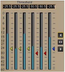 The Threshold is the point of reference for the operation of the L360° Peak Limiter. Whenever the level of a certain channel exceeds the specified threshold, gain attenuation will be applied, reducing the excessive signal peak to the threshold.
The Threshold controls are represented by little arrows next to a channel’s input meter. Some channels will be grouped or linked to a common sidechain. The Threshold controls will get a color per the sidechain they are linked to, in conjunction with the selected Link Mode. Channels that are linked and have the same color, will move together, It is not possible to define separate threshold values to linked channels.
Range: 0 to –48dB, default 0dB.
A Global Threshold control ![]() is located between the Threshold and Ceiling sections. It is the top one of the three global controls, showing an arrow directed toward the threshold section. This control will move all the threshold controls at once, preserving any offsets between the different linked groups. The range and value of this control is subject to the actual Threshold controls. The highest and lowest threshold values set boundaries for the control of the Global Threshold, so if you have a threshold at 0dB and another at –48dB, the Global Threshold control will not make any adjustment.
is located between the Threshold and Ceiling sections. It is the top one of the three global controls, showing an arrow directed toward the threshold section. This control will move all the threshold controls at once, preserving any offsets between the different linked groups. The range and value of this control is subject to the actual Threshold controls. The highest and lowest threshold values set boundaries for the control of the Global Threshold, so if you have a threshold at 0dB and another at –48dB, the Global Threshold control will not make any adjustment.
CEILING CONTROLS
In the Output or Ceiling section each channel has a meter and beside the meter an arrow control that sets and indicates the Ceiling, or maximum peak value, for that channel and other channels linked to the same sidechain. The Ceiling controls behave exactly as the Threshold controls.
Range: 0 to –48dB, default 0dB.
A Global Ceiling control ![]() is located between the Threshold and Ceiling sections. It is the bottom one of the three global controls and it shows an arrow pointing toward the Ceiling section. This control will move all the Ceiling controls simultaneously preserving any existing offsets and bounded by the highest and lowest threshold values.
is located between the Threshold and Ceiling sections. It is the bottom one of the three global controls and it shows an arrow pointing toward the Ceiling section. This control will move all the Ceiling controls simultaneously preserving any existing offsets and bounded by the highest and lowest threshold values.
GLOBAL LIMITER CONTROL![]() The Global Limiter control is located between the Input/Threshold and Output/Ceiling sections. It is the middle one between the Global Threshold and Global Ceiling controls and it shows two arrows pointing sideways to the Threshold and Ceiling sections.
The Global Limiter control is located between the Input/Threshold and Output/Ceiling sections. It is the middle one between the Global Threshold and Global Ceiling controls and it shows two arrows pointing sideways to the Threshold and Ceiling sections.
This control will move all Threshold controls and all Ceiling controls, simultaneously preserving all current offsets with the highest and lowestThreshold or Ceiling values bounding its effective range.
Because this control moves both Threshold and Ceiling, it is quite useful for beginning the limiting operation without hearing the increase in level but just the manipulation of the sound. In this guide’s “Using L360° – Basic Operation” section, most of the setting is done with just this one control, then boosting gain with the Global Ceiling control.
LINK MODE SELECTOR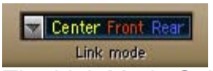 The Link Mode Selector allows the selection of one of five available link modes. It is located directly under the Attenuation meters section. A Link Mode defines which channels are linked to which side chain. Selecting a certain Link Mode will also affect the colors of the Threshold and Ceiling controls that will change to the appropriate group color of the related sidechain. To better understand LinkModes, read section 3: “Link Modes in L360°”.
DITHER![]() On/Off – default on.The Dither adds low level random noise and forces any quantization error noise to become part of the dither noise. It is used to get the highest perceived resolution when taking the 48-bit double-precision process back to 24-bit.
On/Off – default on.The Dither adds low level random noise and forces any quantization error noise to become part of the dither noise. It is used to get the highest perceived resolution when taking the 48-bit double-precision process back to 24-bit.
INPUT METERS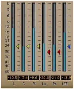 The input meters are the ones in the Threshold section. The Threshold arrow controls were placed beside the meter for easy adjustment of the threshold value in conjunction with the energy in the related channel. Below the Input Meters are peak indicators that show the peak energy and can be reset by clicking on them. Input meters show 0 to –60dBfs.
OUTPUT METERSThe Output meters are the meters in the Ceiling section. The Ceiling Arrow controls were placed next to the output meter for easy adjustment of the output peak value for the relating channel. Below the Output Meters are peak indicators that show the peak energy for the related channel and can be reset by clicking on them. Output meters show 0 to –60dBFS.
ATTENUATION METERS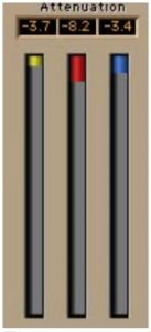 The 3 attenuation meters show the gain attenuated for each of the 3 possible sidechains according to the selected Link Mode. Attenuation will show only for active sidechains whenever the level in one or more of the channels linked to it exceeds the specified Threshold. Above the Attenuation meters there are numeric peak attenuation indicators. These will show the maximum attenuation applied to a certain group until reset by clicking on them. The attenuation meters measure down to 30dB of gain reduction.
References
[xyz-ips snippet=”download-snippet”]