![]()
![]() WAVES/ABBEY ROADEMI TG12345USER GUIDE
WAVES/ABBEY ROADEMI TG12345USER GUIDE
Chapter 1 – Introduction
1.1 WelcomeThank you for choosing Waves! In order to get the most out of your new Waves plugin, please take a moment to read this user guide.
To install software and manage your licenses, you need to have a free Waves account. Sign up at www.waves.com. With a Waves account, you can keep track of your products, renew your Waves Update Plan, participate in bonus programs, and keep up to date with important information.
We suggest that you become familiar with the Waves Support pages: www.waves.com/support There are technical articles about installation, troubleshooting, specifications, and more. Plus, you’ll find company contact information and Waves Support news.
1.2 The Original EMI TG12345 ConsoleIn 1968, the introduction of 8-track recording and increasing sonic experimentation by the Beatles and other groundbreaking artists meant that the capabilities of Abbey Road Studios’ REDD .37 and REDD .51 consoles were being stretched to the max. This called for a new desk.
The year before, EMI had already laid out ideas for a solid-state mixer to replace the valve REDD desks. Throughout 1967, meetings had taken place between the Abbey Road staff and the engineers at EMI Central Research Laboratories in order to design a comprehensive mixing console that would be able to handle the needs of the latest music recordings.
The resulting console, TG12345, was designed to meet the most demanding recording requirements of its time. It was substantially bigger than the old REDD desks, with 24 mic inputs and 8 outputs, 4 echo sends, 2 CUE/foldbacks, and, for the first time ever, a compressor/limiter on every channel, in addition to EQ. The compressor was based on the valve Fairchild and Altec devices used at Abbey Road during the ’60s but ended up with a completely unique sound all its own. The desk was also modular in design, with twelve microphones ‘cassettes’, or channel strips, that could easily be replaced when faulty. Each cassette contained two input channels that could be used either separately or as a stereo pair.
All in all, the desk had no less than 479 knobs and controls as well as 37 meters. Since it was larger than other consoles (a staggering 79.5’’ in width), engineers sitting at the center of the desk were unable to reach all the controls.
For several months in the summer and fall of 1968, the new desk was placed in the studios’ ‘experimental room’ for testing. Abbey Road’s engineers ran ‘clone’ sessions to compare TG12345 and REDD, with two sets of mics placed in the room: one going to the REDD .51, the other to the TG. The results were superb: TG12345 proved to have a cleaner, brighter and punchier sound than its predecessor, with unprecedented top-end sheen and sparkle.
On the weekend of November 23, 1968, TG12345 MK I was installed in the control room of Abbey Road’s Studio Two and connected to the 3M 8-track tape machine. It was first used in a recording session with the Shadows. In mid-1969, the very last Beatles album, Abbey Road, was made on the TG12345.
The TG12345 went through several revisions during the 1970s. TG12345 MK II replaced the treble filter with the same presence filter that existed on the main and group cassettes of MK I. The ergonomics of the dynamics section also underwent changes. MK III and MK IV added new utility options, but the sound processors (dynamics and filters) remained unchanged.
1.3 The EMI TG12345 PluginThe TG12345 plugin is a channel strip with a three-band EQ. Its treble filters deliver a fixed bell filter at 5K for boost and a fixed shelf filter at 10K for a cut. The bass filters are fixed shelf filters at 50 Hz. We have also added a bell filter for presence boost/cut, ranging from 500 Hz to 10 kHz. In the original TG12345 MK I desk, the presence filter was part of the group cassette. We have added it to the TG12345 channel strip for a better user experience.
The TG12345 has a Dynamics section with a limiter/compressor (7:1 and 2:1, respectively) that has a fixed attack time and six options for release time.
The plugin offers three routing options, allowing users to determine where to place the EQ (Bass + Treble), Presence, and Dynamics sections within the signal flow:
- EQ>>Dyn>>Pres – EQ first, then Dynamics, then Presence.
- Dyn>>EQ>>Pres – Dynamics first, then EQ, then Presence.
- EQ>>Pres>>Dyn – EQ first, then Presence, then Dynamics.
The default setting is EQ>>Pres>>Dyn. Together, these three options run the gamut of the routing options offered by the different versions (MK I-IV) of the original TG12345 desk.
The TG12345 has a unique spread control, which is an MS matrix-type process. This control can decrease and increase the level of the sides without touching the level of the mid.Waves have also added several features, not in the original console: (1) a high-pass filter on the sidechain that helps preserve low frequencies during compression, (2) a mix control that gives you control over the balance of the compressed and non-compressed signals, just as in parallel compression, (3) drive, (4) noise.
1.4 Concepts and Terminology
VCAA VCA, or voltage-controlled amplifier, is an amplifier that varies its gain depending on a control voltage, such that the input voltage determines the output voltage. The TG12345 includes a VCAbased compressor. However, whereas most VCA-based compressors only attenuate the signal (voltage in > voltage out), the TG12345’s compressor also amplifies it (upwards compression) at very low levels (below 1.5 V).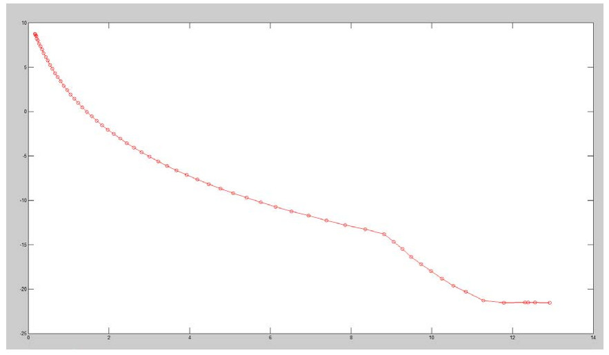 In the graph above, the Y-axis represents the amount of amplification or attenuation in dB, while the X-axis represents the input to the VCA in volts (0 dBfs = 13.875 V). As the graph shows, signals below 1.5 V are boosted while signals above 1.5 V are attenuated. The VCA input is triggered by the feedback signal through the sidechain.
Feedback CompressionThe signal entering the compressor is sent to the VCA. The output of the VCA has then split: one copy goes to the output, while the other is fed back to the VCA via a sidechain circuit. See the image below: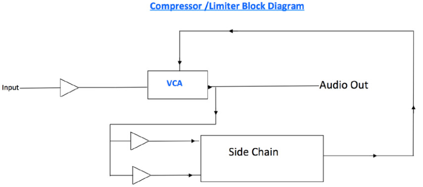 Sidechain High Pass (SC-HP)As explained in the Feedback Compression section above, the input signal is fed to back to the VCA. Generally, the more energy you have in the sidechain, the more compression you get; but if you apply a high-pass filter to remove low energy from the signal, the result is less energy when low-frequency energy is present, hence less compression. In the case of a bass guitar, for example, the abundance of low energy entails lots of compressions; but if a high-pass filter is applied on the sidechain, the VCA will identify less energy on the low bass notes than there is in the actual input signal and will therefore attenuate the signal less, allowing more low frequency.
Sidechain VoltageThe sidechain section of the TG12345 converts the signal from AC to DC, with the VCA controlled via the DC current. The higher the DC current, the more compression you get. The sidechain voltage can range from a couple of mV to 15 V. The amount of compression for each volt is represented in the VCA graph above.
TG12345 CassettesThe original TG12345 desk included three main sections, or three types of “cassettes” (technically there were six types of cassettes, but only three were significant sound-wise; the other three were utility cassettes):
- Microphone Cassette: This section had the mic preamp, an EQ (treble + bass) section, a dynamics section, sends + returns, a spread, a pan pot, and faders. Each cassette was actually a stereo channel, with the option of summing the signal to mono. In TG12345 MK II, the treble EQ was replaced with a presence EQ and the spreader was removed.
- Group Cassette: There were two group cassettes, each containing two subgroups. Any of the microphone cassettes could be routed to a group cassette, and multiple channels routed from the mic cassette to the group cassette could be controlled through the group channel. The group cassette had another dynamics section as well as a presence control (in the TG12345 MK II, this presence control replaced the treble EQ).
- Main Cassette: The TG12345 had five main cassettes: four feeding the tape machine (each was a stereo cassette, for a total of eight tracks), and one for the aux stereo outputs. Each main cassette had another presence EQ section to adjust the final output to the tape.
If you review the routing on the TG12345 plugin, you will see that you can achieve any signal flow within the console using two instances of the plugin. A signal flow simulating a mic-cassette-to group-cassette flow on the TG12345 MK I can be achieved using just one instance (EQ>Dyn>Pres).
1.5 Components
WaveShell technology enables us to split Waves processors into smaller plugins, which we call components. Having a choice of components for a particular processor gives you the flexibility to choose the configuration best suited to your material. TG12345 includes the following components:
- TG12345 Mono
- TG12345 Stereo
1.6 WaveSystem Toolbar
Use the bar at the top of the plugin to save and load presets, compare settings, undo and redo steps, and resize the plugin. To learn more, click the icon at the upper-right corner of the window and open the WaveSystem Guide.
Chapter 2 – Interface and Controls
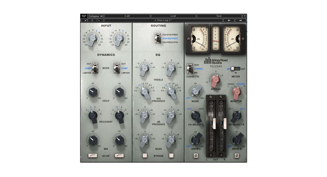
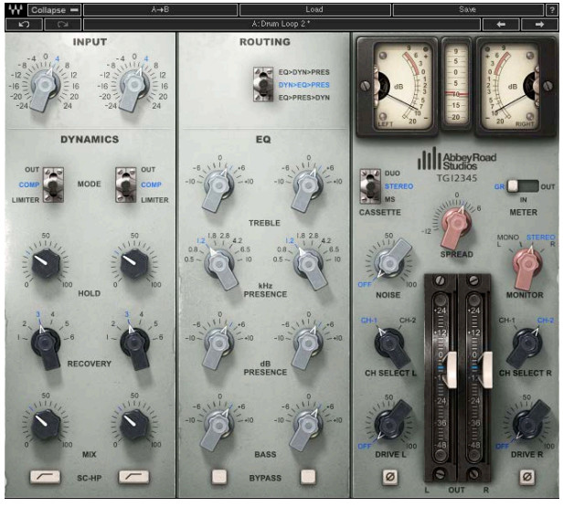
2.1 Interface 2.2 Controls
 2.2 Controls
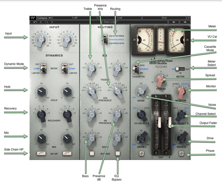
InputIncreases or decreases the gain of the signal.Range: -24 dB to 24 dBDefault: 0 dB
RoutingAllows you to order the signal flow — EQ (Treble + Bass), Presence, Dynamics — in one ofthree ways:
- EQ>Dyn>Pres – EQ first, then Dynamics, then Presence
- Dyn>EQ>Pres – Dynamics first, then EQ, then Presence
- EQ>Pres>Dyn – EQ first, then Presence, then Dynamics
Default: EQ>Pres>DynDynamicsModeAllows you to choose between three dynamic modes:
- Out – In this mode, the Dynamics section is bypassed.
- Compressor – Compressor mode (2:1), with attack fixed to 1 ms.
- Limiter – Limiter mode (7:1) with attack fixed to 1 ms.Default: Out
HoldSets a constant DC voltage for the sidechain that feeds the VCA (for more information on VCA, see the Concepts and Terminology section on p. 5 above). This constant voltage causes a fixed amount of attenuation throughout the signal. When the input voltage that reaches the sidechain is greater than the voltage set by the Hold control, the plugin’s simulated diode is breached, and VCA is triggered by a changing DC voltage, causing the gain change to vary according to the VCA characteristics. When the input voltage is lower than the voltage set by the Hold control, the amount of attenuation is once again constant. This control is the only way for you to narrow the VCA’s gain change range.
The way to use the Hold control is this: set the meter to GR, change the Hold level until you get the overall amount of compression you want, then make up for the gain loss using the output faders. Many compressors operate by linking the hold control to the output faders (the threshold), but the TG12345 is unique in keeping them separate.Range: 0–100Default: 0
RecoverySets the release time, with six states for each dynamic mode.Range: 100 ms, 250 ms, 500 ms, 1 sec, 2 sec, 5 sec.Default: 100ms
SC-HPApplies a high-pass filter on the sidechain signal at around 90 Hz, resulting in lesscompression on the low end.Range: On, OffDefault: Off
MixControls the balance between the compressed and uncompressed signal.Range: 0% to 100% (0.1% increments)Default: 100%
EQ
TrebleBoost: Bell filter fixed at 5 kHzCut: Shelf fixed at 10 kHzRange: -10 dB to 10 dBDefault: 0 dB
Presence (kHz)Bell filter controls the center frequency of the presence filter.Range: 500 Hz to 10 kHz (continuous)Default: 1.8 kHz
Presence (dB)Boosts/cuts the presence filter.Range: -10 dB to 10 dBDefault: 0 dB
BassLow shelf filter fixed at 50 Hz.Range: -10 dB to 10 dBDefault: 0 dB
EQ BypassBypass’s the whole EQ sectionRange: On OffDefault: Off
Master SectionPhaseInverts the phase of the signal (one per channel).Range: On/OffDefault: Off
Channel SelectorTwo channels of the original TG12345 desk have been modeled: Channels 1 and 2.
- Mono: Select Channel 1 or 2
- Stereo: Select Channel 1 or 2 for L, R, or both
- L default: Channel 1
- R default: Channel 2
Note: To keep your stereo image as close as possible to your input, select the same channel for both L and R.
DriveControls the amount of drive added to the processed signal.Range: Off to 100Default: Off
NoiseControls the amount of noise and hum added to the processed signal.Range: Off to 100Default: Off
Spread (Stereo Component Only)Controls the balance between the mid and sides by changing the level of the sides only, while the level of the mid remains constant. This feature is available in all cassette modes not just in MS. The spread is very similar to an MS matrix; it is faithful to the plugin’s analorigins, however, in that the encoding and decoding of the matrix do not cancel each other perfectly, giving the spread its distinctive vintage character.Range: -12 dB to 6 dB (0.1 dB increments)Default: 0
Monitor (Stereo Component Only)Selects the source of the monitor output.
- Left – Left output is sent to both sides (in MS Mode this monitors the mid)
- Mono – Left and Right outputs are summed to mono and trimmed down by 6 dB
- Stereo – Stereo mode
- Right – Right output is sent to both sides (in MS Mode, this monitors the sides)Default: Stereo
OutputTwo faders (one per channel) that control output gain after processing.Range: -48 dB to 24 dBDefault: 0 dB
MeteringVU MeterDisplays input, output, and gain reduction levels, depending on your selection.Range IN/OUT: -20 VU to 3 VURange GR: -20 VU to 9 VU
Peak MeterDisplays signal peak output level.Range IN/OUT: -20 dBfs to 0 dBfsRange GR: -20 dBfs to 9 dBfs
VU Meter – Headroom Calibration ControlThe meter’s headroom calibration default is set to 18 dB headroom. The meter can be adjusted using the little screw underneath to provide a headroom of 8 to 24 dB (or -8 to -24 dB), where X dBfs = 0 VU.Range: 8 dB to 24 dB / -8 dB to -24 dBDefault: 18 dB
Meter I/OThe meter I/O lets you select from three monitoring modes:GR: Shows the total amount of gain reduction/increase.IN: Shows the input signal level post-input control, so that any change in the input is reflected in the meter.OUT: Shows the output level of the plugin post-output control, so that any change in the output is reflected in the meter.Please note: Some constant amplification factors are not reflected in the GR meter because they are fixed and not signal-dependent. This is why what you see on the GR meter will not necessarily reflect what you are hearing.Range: GR / IN / OUTDefault: IN
Clip IndicatorIndicates peak clipping.
Waves / Abbey Road TG12345User Guide
References
[xyz-ips snippet=”download-snippet”]