
OVERVIEW
Stepper Motor HAT is designed for Raspberry Pi, can drives two stepper motors andsupport up to 1/32 micro stepping
FEATURES
- Raspberry Pi connectivity, compatible with Raspberry Pi Zero/Zero W/Zero WH/2B/ 3B/3B+
- Onboard dual DRV8825 motor controller IC with built-in micro stepping indexer, drives two stepper motors, easy to use
- 6 available micro stepping modes, configured with the DIP switches: full-step, half step, 1/4-step, 1/8-step, 1/16-step, and 1/32-step
- Adjustable motor drive current via potentiometer, maximum 2.5A current output
- Protection features: Overcurrent Protection (OCP), Thermal Shutdown (TSD), VM Under voltage Lockout (UVLO)
- Integrates 5V regulator, allows providing power to Raspberry Pi
- Onboard multi connector options for stepper motors in different specifications
- Comes with development resources and manual (examples in BCM2835, wiringPi, and python)
SPECIFICATIONS
- Motor controller: DRV8825
- Motor drive voltage: 8.2V~28V
- Motor drive current: 2.5A
- Logic voltage: 3.3V
- Dimension: 65mm × 56mm
- Mounting hole size: 3.0mm
HARDWARE
PINOUT

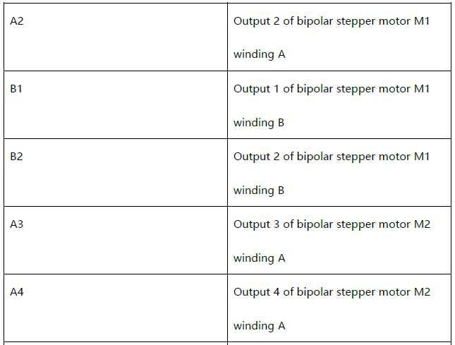
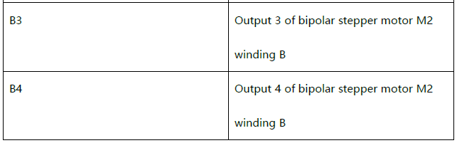
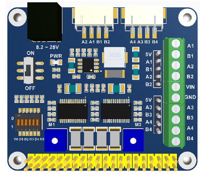
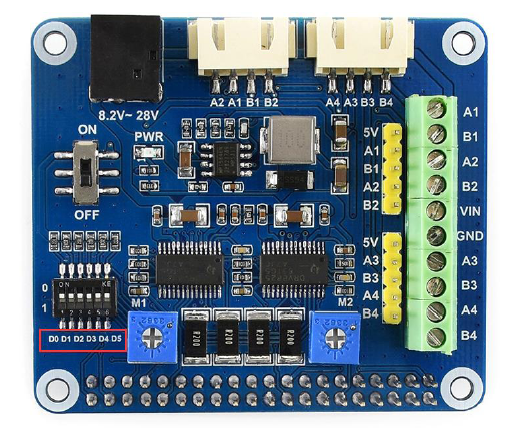
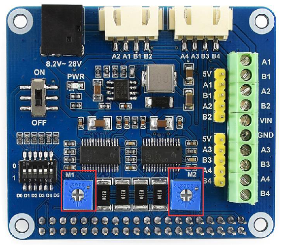
A1、A2、B1、B2: Control pins of stepper motor M1;A3、A4、B3、B4: Control pins of stepper motor M2;Power switch: Control power supply for Raspberry Pi;Switch D0-D5: Control subdivision format;D0-D2: Control stepper motor 1;D3-D5: Control stepper motor 2;Potentiometers: Control output current
POWER
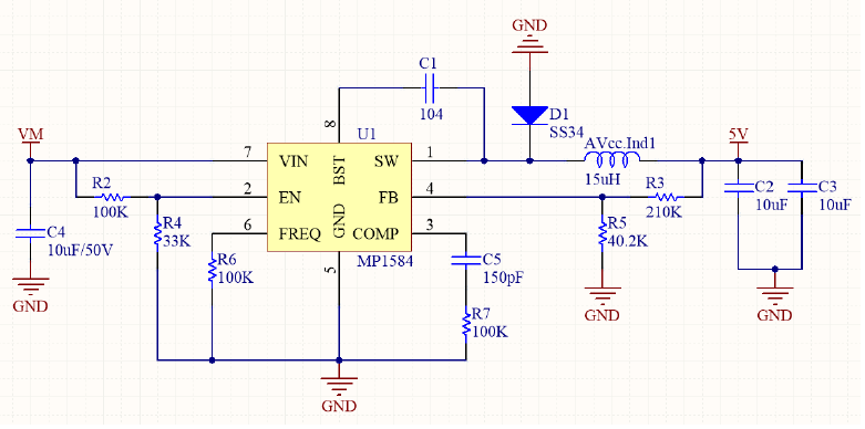
MP1584 regular supports wide 4.5V to 28V input, and up to 2A current output. Eventhought that MP1584 support low to 4.5V input, however, VM also supply power formotor controller, which require at least 8.2V. So, the recommend input voltage is8.2~28v.
MOTOR DRIVER
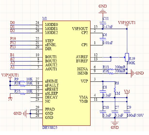
The DRV8825 is e has two H-bridge and a microstepping indexer, and is intended to drive a bipolar stepper motor. It supports up to 1/32 microstepping. Internal shutdown functions are provided for overcurrent, short circuit, under voltage lockout and over temperature.
VM:Voltage input, range: 8.2V~45V, consider of regular, the actual input range is:8.2V~28V
nSLEEP: Should keep High, otherwise chip will enter sleep mode, and module cannotwork properly.nENBL: Enable pin. Low: H-bridge is enabled and rise edge of STEP is sampled; High:H-bridge is disabled, output is high impedance. Note that you should disable it ifyou don’t use it, otherwise the chip and motor will keep heating!STEP: Step clock inputDIR: Direction controlMODE0, MODE1, MODE2: Mcirostepping input
PIN 12/PIN 13: Adjust output current R13/R16: Sample resistors, they are 0.2ΩAccording to datasheet Page11: Ichop = V(xREF)/(5*R(ISENSE)) and resistor is 0.2Ω, then we can get that output current is proportional to voltage of potentiometer.I = Vref
So, if you need to increase the output current, you can adjust potentiometers on board.
8.3.2 Current Regulation
The current through the motor windings is regulated by a fixed-frequency PWM current regulation. or current chopping. When an H-bridge is enabled, current rises through the winding at a rate dependent on the DC voltage and includance of the winding. Once the current hits the current chopping threshold, the bridge disables the current until the beginning of the next PWM cycle.
In stepping motors current regulation is used to vary the current in the too windings In a semi-sinusoidal fashion to provide smooth moton.
The PWM chopping current is set by a comparator which compares the voltage across a current sense resistor connected to the xISEN pins, multiplied by a factor of 5, with a reference voltage.
The reference voltage is input from the uVREF pins.
The full-soale (100%) chopping current is calculated in Equation 1.
ICHOP = VxREF /5 x RISENS
Example: If a 0.25-0 sense resistor Is used and the VIREPy pin Is 1.5 V, the Mil-scale (100%) chopping current will be 2.5V/(5x 0.25 fl) = 2A.
H-BRIDGE
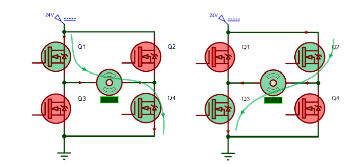
H-bridge is a popular motor control circuit. It is named because it looks like character “H”. It consists of four transistors/MOSFET, motor is connected on the center, you should through two transistors in diagonal line to drive motor.When Q1 and Q4 is accessed, current flow from positive pole->Q1 to Q4->negative pole, then motor moves forward.When Q2 and Q4 is accessed, current flow from positive pole->Q2 to Q4->negative pole, then motor moves backward.If it is two H-bridge, there will be two set of output lines, for example, stepper motor has four wires which is two H-bridge.
PROTOCOL OF MOTOR

According to Ampère’s circuital law, when current of coil A flow from left to right, stator generates magnetic field, internal side is North pole which will adopt rotator of motor. When the currents of four coils based on certain rule, they will generate a rotate magnetic field and drive the rotator rotate. If every motor has four rotators, it has four statuses:Status 1: coil A left in right out(current), coil C right in left out, motor rotate 0 degree;Status 2: coil B top in bottom out, coil D bottom in top out, motor rotate 90 degree against status 1.Status 3: coil A right in left out, coil C left in right out, motor rotate 90 degree against status 2;Status 4: coil B bottom in top out, coil D top in left out, motor rotate 90 degree against status 3;Motor turn from previous status to next status, we call it step. Motor rotate in a circle every four steps, and its step angle is 90 degree.Most of motors have more than four stators. For example, 42 motor, 57 motors all have 50 stators with step angle 1.8 degree.
28BYJ-48 is four phase and eight steps, Speed Variation Ratio is 1/64 and its step angle is 5.625/64 degree.
MICROSTEPPING
We have said that motor rotate because of flowing current.According to its working principle, we can control currents in coils to make them rise or fall regularly. It generates several stable intermediate-current statuses, related vector directions of resultant magnetic fields also have several intermediate statuses. To change the vector direction, motor can rotate in smaller angle and rotate more smoothly.
Microstepping is to divide each full step into smaller steps to help smooth out the motor’s rotation, especially at slow speeds. For example, if microstepping the motor we described above to 1/2, status 1 should be done with two steps.
DRV8825
DRV88250 control stepper motor rotating according to pulses given by MCU.How many pulses do motors require to rotate a circle without microstepping?42 motor: 360/1.8 = 20028BYJ-48 motor: 360 / 5.625 * 64 = 4096As we test, with 200 pulses, 42 motor can rotate a circle. However, with 4096 pulses, 28BYJ-48 rotate two circles. That is because 28BYJ-48 is four-phase motor require 2048 pulses for a circle actually.
DEMO CODES
PREPARATIONDOWNLOADINGVisit Waveshare Wiki and search for “Stepper Motor HAT”, open and download demo code from wiki.

1. Install wiringPi
1.1 Open Terminal (Ctrl+T), clone wiringPi git clone git://git.drogon.net/wiringPi
1.2 Install it
cd wiringPi./build
2. Install BCM2835
2.1 Download the latest bcm2835 libraryhttp://www.airspayce.com/mikem/bcm2835/index.html2.2 Copy the zip you download to Raspberry Pi without extracting2.3 Open Terminal, extract and install
#下载最新的函数库bcm2835-1.xx.tar.gztar zxvf /boot/bcm2835-1.xx.tar.gzcd bcm2835-1.xx./configuremakesudo make checksudo make install
3. Install python library
sudo apt-get install python-rpi.gpio
SETTING
MICROSTEPPINGStepper motor HAT support up to 1/32 microstepping. Support both software and hardware configuring.
Software configuringIn the demo codes, you can configure the microstepping by SOFTWARD/softward which you can refer to Code Analysis .
Hardware configuringTo use hardware configuration, you need to modify the functionDrv8825_SetMicroStep(HARDWARE, “”) in sample codes, then set the DIP switches (D0~D5).
D0, D1, D2 are used to control motor M1 (MODW0, MODE1, MODE2), D3, D4, D5 are used to control motor M2 (MODE0, MDOE1, MODE2). Their relationship are as below:
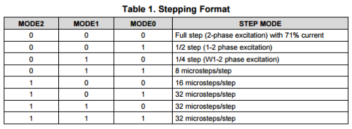
For more details, please refer to datasheet page13【Note】Sample codes uses full step setting, for which all switches are set to 0 by default.
CURRENT SETTINGThe maximum output current of DRV8856 is 2.5A, you can adjust current by adjustingthe potentiometer The maximum output current of DRV8856 is 2.5A, you can adjust current by adjusting the potentiometer
Generally, working current of stepper motor is less than 2.5A, in this case, we need to adjust the current outputted.
For more details about the current required, please refer to datasheet page12.The R(isense) on board is 200mR, so we can get that I(chop) = V(xref). V(xref) is voltage of potentiometer, Ichop is output current. Reduce voltage by clockwise and anticlockwise to increase the voltage.The factory setting is compatible with most of stepper motor. However, there are some motor whose minimum phase current is much larger, in this case, we need to adjust the potentiometer for properly working.
【Note】Chip may be damaged if motor works in abnormal states for long time.Do not turn the potentiometer anticlockwise to maximum, otherwise, the chip will be damaged after long time using.
RUNNING DEMO CODE
BCM2835cd bcm2835sudo ./motor
WIRINGPIcd wiringpisudo ./motor
PYTHONcd pythonsudo python test.py
CODE ANALYSIS
We provide Raspberry Pi demo codes on wiki.BCM2835
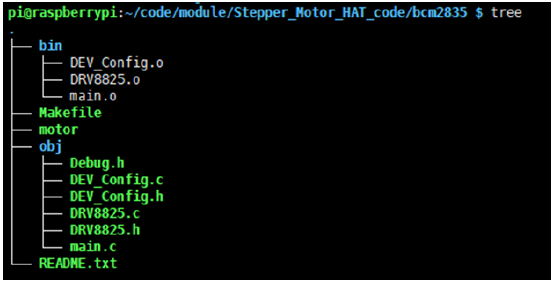
FILES
- bin: .o files which are generated by makfile
- Makefile: Code compilation
- motor: Executable file, you can execute command sudo ./motor to run the code
- Obj/: folders to save function files
Debug.h: Debug header file, you can set USE_DEBUG to 1 to print debug information;Deconflict(h): Define pins and interface of Raspberry Pi.DRV8825.c(h): Driver code of DRV8825main.c: Main functionREADME.txt: Description
CODES
- Initializing BCM2835 and setting pinsif(DEV_ModuleInit())exit(0);
- Choose MotorDRV8825_SelectMotor(MOTOR1);#Parameter: choose motor; MOTOR1, MOTOR2
- Setting MicrosteppingDRV8825_SetMicroStep(HARDWARD, “fullstep”);#Parameter 1: set control type; HARDWARE, SOFTWARD#Parameter 2: set microstepping; “fullstep”, “halfstep”, “1/4step”, “1/8step”,“1/16step”, “1/32step”
- StepsDRV8825_TurnStep(BACKWARD, 200, 2);#Parameter 1: control direction; FORWARD, BACKWARD#Parameter 2: steps#Parameter 2: delay for every step (ms)
- Stop rotatingDRV8825_Stop();
- Exception Handlingsignal(SIGINT, Handler);
If you use CTRL+C to stop the code, DRV8825 chip may doesn’t be disabled, so this function is used to handle such case. Ctrl+C generates signal SIGINT, Handler() function is executed when the signal generated.The Handler() work with these statements:
DRV8825_SelectMotor(MOTOR1);DRV8825_Stop();DRV8825_SelectMotor(MOTOR2);DRV8825_Stop();
WIRINGPI
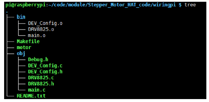
FILESSimilar to BCM2835, differences are:DEV_Config.c(h): Library called is differentMakefile: linking library is different
PYTHON
FILES
 DRV8825.py is driver code of DRV8825, which is used to control stepper motor.test.py: test codeCODEStest.py:
- Instantiate DRV8825 library
Motor1 = DRV8825(dir_pin=13, step_pin=19, enable_pin=12, mode_pins=(16,17, 20))
2. Set microsteppingMotor1.SetMicroStep(‘softward’,’fullstep’)#Parameter 1: control type, ‘software’, ‘hardware’#Parameter 2: microstepping, ‘fullstep’,’halfstep’, ‘1/4step’,‘1/8step’, ‘1/16step’, ‘1/32step’
3. stepsMotor1.TurnStep(Dir=’forward’, steps=200, stepdelay = 0.005)#Parameter 1: control direction, ‘forward’、’backward’#Param3ter 2: steps#Parameter 3: delay (ms)
4. StopMotor1.Stop()#Must be used to disable chip
FAQ
- Why the motor and chips on modules get serious hot?Energy efficiency of stepper motor is very low, has only 20%~30% useful work, others become heat. So, stepper motor will get very hot after running for long time. Do not touch!!! By the way, check if you use function DRV8825_Stop() to disable chip
- The module could be used to drive motors whose working current is less than1.5A without heat sink. Normally, it supports up to 2.5A.
- Why doesn’t motor work and only shake left and right?Motor shake when lack-phase, try to connect motor with Dupont lines if both interfaces of module cannot work properly.
- Why do motor desynchronize?The phase current is based on torsion of stepper motor. You can adjust the blue potentiometer if motor desynchronize.
- Why do motor sound “si si” when stopping?It is normal.
- How to switch control type?You can change the setting on codes, “Hardware” or “Software”.It default use hardware control. If you want to change to software control, you need to weld resistors on the backside of PCB and turn all switches to 1.
[xyz-ips snippet=”download-snippet”]