
![]()
Submersible Sump Pump System
Please read and save these instructions. Read carefully before attempting to assemble, install, operate or maintain the product described. Protect yourself and others by observing all safety information. Failure to comply with instructions could result in personal injury and/or property damage! Retain instructions for future reference.
Operating Instructions and Parts Manual WSS30Vn
| SPECIFICATIONS | ACSPECIFICATIONS | DCSPECIFICATIONS |
| POWER SUPPLYREQUIREMENTS | 120 V, 60 Hz | 12 V, DC* |
| MOTOR | Single Phase, Dielectric Oil Filled | Permanent Magnet DC |
| POWER | 1/2 HP | 100 Watts |
| CIRCUITREQUIREMENTS | 15 A (minimum) | 15 A (minimum) |
| DIMENSIONS | 11 ½ in. high x 9 ¾ in. base | 11 ½ in. high x 9 ¾ in. base |
| ON LEVEL | Approximately 9 in. | 10-12 in. |
| OFF LEVEL | Approximately 4 in. | N/A |
| CONSTRUCTION | AC | DC |
| MOTORHOUSING | Coated Steel | |
| VOLUTE | Cast Iron | |
| IMPELLER | Glass Reinforced Thermoplastic | |
| SHAFT | Steel | Stainless Steel |
| DISCHARGE | 1-1/2 in. NPT |
| PERFORMANCE GAL/HR | |||||
| Model | HP | Discharge Head (Lift Distance) | |||
| 0 ft | 5 ft | 10 ft | 15 ft | ||
| WSS30Vn AC | ½ | 5100 | 4500 | 3840 | 3060 |
| WSS30Vn DC | 12 V | 2700 | 2100 | 1500 | 660 |
* Battery not included. A Wayne WSB1275 75 Amp Hour Battery is recommended
Intended for Indoor Use Only
© 2020, WAYNE/Scott Fetzer Company www.waynepumps.com 670006W-001 H 02/20
Operating Instructions and Parts Manual
SYSTEM DESCRIPTION
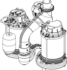
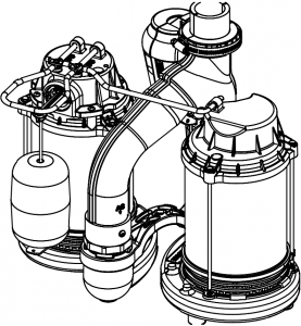
This product is fully assembled and pre-plumbed 1/2 HP primary & 12 Volt backup sump system. The pumps are designed for use in residential basements to remove groundwater and prevent flooding. The pumps are designed for clear water only. LED indicator lights inform the howeowner of the charge status of the battery. Wayne recommends the WSB1275, 75 Amp Hour maintenance free battery (sold seperately), to complete the system. Designed for 15 in. diameter or larger sump basins. This system is intended for indoor use only.
Installation of this system outdoors, unprotected from the weather, may cause hazardous conditions and will void warranty. If using outdoors, protect pump from direct weather elements such as sun, rain, sleet, snow, and extreme temperature changes. Water inside the pump may freeze, limiting its performance and damaging the pump and pipes.
UNPACKING
Inspect this unit before it is used. Occasionally, products are damaged during shipment. If the pump or components are damaged, return the unit to the place of purchase for replacement, or call Customer Support (800-237-0987).
SAFETY SIGNAL WORDS
This manual contains information that is very important to know and understand. This information is provided for SAFETY and to PREVENT EQUIPMENT PROBLEMS. To help recognize this information, observe the following symbols.
![]() DANGER Danger indicates an imminently hazardous situation which, if NOT avoided, WILL result in death or serious injury.
DANGER Danger indicates an imminently hazardous situation which, if NOT avoided, WILL result in death or serious injury.
![]() WARNING Warning indicates a potentially hazardous situation which, if NOT avoided, COULD result in death or serious injury.
WARNING Warning indicates a potentially hazardous situation which, if NOT avoided, COULD result in death or serious injury.
![]() CAUTION Caution indicates a potentially hazardous situation which, if NOT avoided, MAY result in minor or moderate injury.
CAUTION Caution indicates a potentially hazardous situation which, if NOT avoided, MAY result in minor or moderate injury.
NOTICE Notice indicates important information, that if NOT followed, MAY cause damage to equipment.
IMPORTANT SAFETY INFORMATION
RISK OF ELECTRIC SHOCK. TO REDUCE THIS RISK, OBSERVE THE FOLLOWING WARNINGS:

MAKE SURE THERE IS A PROPERLY GROUNDED RECEPTACLE AVAILABLE. The AC pump & transformer are supplied with a grounding conductor and grounding-type attachment plug. To reduce the risk of electric shock, be certain that it is connected only to a properly grounded, grounding-type receptacle.
FOR ADDED SAFETY the receptacle must be protected with a ground fault circuit interrupter (GFCI). All wiring must be performed by a qualified licensed electrician and comply with the National Electric Code and all applicable local codes and ordinances.
NEVER REMOVE THE GROUND PRONG from the plug or bypass the grounding wires.
NOTICE
THIS SYSTEM IS NOT DESIGNED TO HANDLE SALT WATER, BRINE, LAUNDRY DISCHARGE, WATER SOFTENER, SEWAGE, GREY WATER, OR ANY OTHER APPLICATION WHICH MAY CONTAIN CAUSTIC CHEMICALS AND/OR FOREIGN MATERIALS. PUMP AND/OR PROPERTY DAMAGE COULD OCCUR IF USED IN THESE APPLICATIONS AND WILL VOID WARRANTY
DO NOT REMOVE POWER SUPPLY CORD and strain relief or connect conduit directly to the pump.
MAKE SURE THE POWER SUPPLY HAS A FUSE OR CIRCUIT BREAKER rated to handle the current (amps) noted on the pump nameplate or cord tag.
Operating Instructions and Parts Manual WSS30Vn
IMPORTANT SAFETY INFORMATION (CONT’D)
ALWAYS DISCONNECT THE PUMP from power supply before installing, servicing or making any adjustments.
DO NOT WALK on the floor when water is present until all power is turned off. If the electric panel is in the basement, call an electrician.
NEVER HANDLE A PUMP or motor with wet hands or when standing on a wet or damp floor while the pump is plugged into the power supply.
RISK OF ELECTRIC SHOCK. This system has not been investigated for use in swimming pool and marine areas.
DO NOT USE TO PUMP FLAMMABLE OR EXPLOSIVE FLUIDS such as gasoline, fuel oil, kerosene, etc. Do not use in a flammable and/ or explosive atmosphere. System should only be used to pump clear water. Personal injury and/or property damage could result and void warranty.
PUMPS ARE NOT DESIGNED TO TRANSFER WATER INTENDED FOR DRINKING. Do not use the pumps for moving water that will be used for portable/drinking water. Pumps should only be used in applications for which it is designed.
 WARNING
DO NOT USE AN EXTENSION CORD OR SURGE PROTECTOR. Extension cords and/or surge protectors could present a safety hazard if not sized properly, become damaged or the connection falls into the sump. If receptacle is not within reach of the pump’s power cord, contact a qualified licensed electrician to install a new receptacle.
TO REDUCE THE RISK OF HAZARDS THAT CAN CAUSE INJURY OR PROPERTY DAMAGE, OBSERVE THE FOLLOWING WARNINGS:
IT IS THE INSTALLER’S RESPONSIBILITY TO MAKE SURE THE PUMPS AUTOMATIC SWITCHES ARE ABLE TO OPERATE WITHOUT ANY OBSTRUCTIONS WITHIN THE BASIN. It is recommended that the installer test and observe the operation for several cycles after installation.
IT IS REQUIRED TO USE RIGID PIPING AND FITTINGS to secure the system in the basin and reduce pump movement. Pump movement can prevent the switch from operating correctly. Do not use flexible hose.
DO NOT INSTALL OR OPERATE THE PUMPS IF THEY HAVE BEEN DAMAGED IN ANY WAY.
DO NOT LIFT OR CARRY THE SYSTEM BY THE POWER CORDS.
Operating Instructions and Parts Manual
IMPORTANT SAFETY INFORMATION (CONT’D)
DO NOT USE THIS SYSTEM IN MUD, SAND, CEMENT, OIL CHEMICALS, GREY WATER, OR ANY OTHER WATER THAT IS NOT CLEAR GROUND WATER.
DO NOT USE SUMP PUMPS TO HANDLE RAW SEWAGE.
WARNING
This product can expose you to chemicals, including DEHP, which is known to the State of California to cause cancer, birth defects and reproductive harm. For more information, go to www.P65Warnings.ca.gov.
WARNING
VERTICAL FLOAT SWITCH This float is not adjustable. Any modifications or alterations will void the warranty and/or cause premature failure of the pump, which could lead to property damage.
BATTERY INFORMATION
The system is designed to operate most efficiently with an AGM battery. A WAYNE WSB1275 is recommended. The over size battery case (included) will accommodate a 12 Volt AGM battery (up to a group 27-frame size).
NOTICE Be certain that the area around the battery is well ventilated. Before servicing the battery, blow away gasses by waving a piece of cardboard near the batteries.
![]() DANGER Dangerous hydrogen gas can be released from the battery while charging. Sparks can ignite the gas in an enclosed space. Wear safely goggles when connecting battery. Battery connections should be made in a well ventilated area.
DANGER Dangerous hydrogen gas can be released from the battery while charging. Sparks can ignite the gas in an enclosed space. Wear safely goggles when connecting battery. Battery connections should be made in a well ventilated area.
![]() DANGER Working in the vicinity of a lead acid battery can be dangerous. Before making the connections or servicing the batteries, read and follow instructions on all applicable instruction manuals. To reduce the risk of battery explosion, follow the instructions in this manual and those published by the battery manufacturer, as well as those of any other equipment used in the surrounding area.
DANGER Working in the vicinity of a lead acid battery can be dangerous. Before making the connections or servicing the batteries, read and follow instructions on all applicable instruction manuals. To reduce the risk of battery explosion, follow the instructions in this manual and those published by the battery manufacturer, as well as those of any other equipment used in the surrounding area.
NOTICE An assistant should be present or close enough to come to your aid in the event of an emergency. Have a reliable source of fresh water and soap nearby in case battery acid contacts skin or eyes.
NOTICE Wear eye and clothing protection when working around lead acid batteries. Avoid touching your eyes when working around lead acid batteries.
![]() WARNING If battery acid contacts your eye(s), flush with cold running water for 10 minutes and seek immediate medical attention. If acid contacts your skin or clothing, wash immediately with soap and water.
WARNING If battery acid contacts your eye(s), flush with cold running water for 10 minutes and seek immediate medical attention. If acid contacts your skin or clothing, wash immediately with soap and water.
![]() WARNING Never smoke or allow a spark or flame in the vicinity of the battery.
WARNING Never smoke or allow a spark or flame in the vicinity of the battery.
![]() WARNING Avoid dropping metal tools on the battery posts because they may spark or short-circuit the system or battery, causing an explosion.
WARNING Avoid dropping metal tools on the battery posts because they may spark or short-circuit the system or battery, causing an explosion.
Operating Instructions and Parts Manual WSS30Vn
INSTALLATION
NOTICE INSTALLATION OF THIS UNIT MAY TAKE SEVERAL HOURS. BEFORE DISABLING YOUR MAIN PUMP, HAVE READY AN APPROPRIATE MEANS OF EVACUATING THE SUMP.
1. Turn power to main pump off.2. Pump must be installed using 1-1/4 in. or 1-1/2 in. rigid PVC piping. Do not use flexible hose.
Figure 1: Submersible Sump System
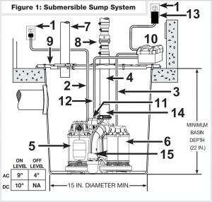
1. GFCI GROUNDED OUTLETS 9. GASKET/BASIN LID2. AC PUMP POWER CORD 10. BATTERY BOX CONTROLLER3. DC PUMP POWER CORD 11. DC FLOAT SWITCH4. DISCHARGE PIPE 12. DC FLOAT SWITCH CORD5. AC PUMP (Primary) 13. TRANSFORMER6. DC PUMP (Secondary) 14. 11/2″ PVC SCHEDULE 40 COUPLING7. VENT PIPE 15. DIVERTER VALVE8. REMOVABLE CHECK VALVE
NOTICE THIS INSTALLATION MUST BE IN ACCORDANCE WITH THE NATIONAL ELECTRIC CODE AND ALL APPLICABLE LOCAL CODES AND ORDINANCES.
3. Use a basin (purchased seperately) or pit that is large enough to accommodate the system. The minimum requirements for the sump system are shown in Figure 1.4. Clean the basin/pit of all debris.5. If using a basin, place the system directly on the bottom of the basin.To prevent damage set the system on a solid, level surface. Do not place units directly on clay, earth, gravel or sand. A brick or blocks can be installed under the pumps to provide a solid base.6. Position system so the float switch is away from the inlet so float switch is clear from incoming water. Verify the float has at least 1 in. clearance to the side wall of the basin and is free to move throughout its travel.7. Install discharge plumbing according to local, regional and state codes. Rigid PVC pipe is required. Do not use flexible hose in a permanent application. A 1-1/2 PVC schedule 40 coupling is required on diverter valve discharge. Do not use schedule 20 couplings or drainage fittings.8. Install removable check valve (8) (Wayne Part Number: 57028-001) positioned just above the basin to allow easy removal of the system for cleaning and service. Note: A check valve is required to prevent back-flow.9. Install a gate valve or ball valve if required by local, regional or state code.10. Connect pump power supply cord to a ground fault circuit interrupter (GFCI) outlet (1).
Operating Instructions and Parts Manual
AC PUMP CHECK
- Fill the basin/pit with water. The pump will start when the water level has reached the float switch-on level.
- The pump will stop when the water level has reached the switch-off level.
- Verify the switch is operating without any obstruction from the pump, piping and basin.
- Fill the basin/pit with water again. While the system is draining the basin/pit, verify the discharge pipe is carrying the water to a point at least 3 ft. away from the foundation. If the discharge line is exposed to freezing temperatures, the pipe must be positioned in a downward slope away from the foundation so any remaining water will drain away and not freeze.
CONTROL BOX INSTALLATION
1. Place battery in box, attach red cable to positive battery post and black cable to negative battery post.
![]() CAUTION If cables are reversed, damage to the control box or battery will result, and void warranty.2. Plug the float, pump system, and transformer into the appropriate connectors. The connections are all unique and cannot be interchanged.3. Put lid on box, and place the battery within six feet of the sump and a 115 VAC separately fused outlet. The outlet must be protected by a ground fault circuit interrupter (GFCI) The area must also be clean, dry and well ventilated.
CAUTION If cables are reversed, damage to the control box or battery will result, and void warranty.2. Plug the float, pump system, and transformer into the appropriate connectors. The connections are all unique and cannot be interchanged.3. Put lid on box, and place the battery within six feet of the sump and a 115 VAC separately fused outlet. The outlet must be protected by a ground fault circuit interrupter (GFCI) The area must also be clean, dry and well ventilated.
![]() CAUTION Do not allow battery box to get wet, or expose it to moisture. Electronics will be damaged and void warranty.
CAUTION Do not allow battery box to get wet, or expose it to moisture. Electronics will be damaged and void warranty.
BACK UP PUMP CHECK
- Test system operation by filling the sump with water while the main pump is unplugged. If the pump operates properly, plug the transformer into the GFCI protected outlet to begin charging the battery.
- Protect electrical cord from sharp objects, hot surfaces, oil and chemicals. Avoid kinking the cord.
- Secure power supply cord to discharge pipe using cable or zip ties to prevent possible switch entanglement.
Operating Instructions and Parts Manual WSS30Vn
OPERATION
![]() DANGER Always disconnect the power source before attempting to install, service, relocate or maintain the pump. Never touch sump pump motor, water or discharge piping when pump is connected to electrical power. Never handle a pump or pump motor with wet hands or when standing on wet or damp surface or in water. Fatal electric shock could occur.
DANGER Always disconnect the power source before attempting to install, service, relocate or maintain the pump. Never touch sump pump motor, water or discharge piping when pump is connected to electrical power. Never handle a pump or pump motor with wet hands or when standing on wet or damp surface or in water. Fatal electric shock could occur.
![]() DANGER Risk of electrical shock! Use a gfci receptacle to reduce the risk of fatal electric shock. Cutting the cord will void the warranty and make the pump inoperable.
DANGER Risk of electrical shock! Use a gfci receptacle to reduce the risk of fatal electric shock. Cutting the cord will void the warranty and make the pump inoperable.
- After installation, the backup pump will start when the water level rises above the backup float switch.
- The control box has a DC charger designed to shorten the recharging time of your battery, and to prevent overcharging. In addition, the control box has a time delay which keeps the pump from repeated, short cycles when it shuts off. The time delay feature will allow the pump to run 20-25 seconds after the switch reaches the off position.
- The control box contains multi-colored indicator lights. When AC power is present, the lights will indicate the charging state, and not reflect actual battery voltage, particularly with a defective battery. In order for the indicator light to provide an accurate reading, steps “a” through “d” must be followed.
![]() DANGER Risk of electrical shock! Unplug main ac pump and the transformer.
DANGER Risk of electrical shock! Unplug main ac pump and the transformer.
a. After main pump and transformer are unplugged, a power off alert tone will sound for 30 seconds.
![]()
b. Press and release the self test button to activate the back up pump.c. When the pump stops, read the charge indicator lights:Green: Indicates the battery is fully charged.Yellow: Indicates battery partially charged, still operable.Red: Battery is completely discharged or defective.Red blinking: Battery discharged below level where pumping can occur. Motor is locked out by controller until battery is sufficiently charged to run pump.d. Plug in transformer and main AC pump.
When main AC power is out, and when pump has been running, the lights will indicate battery status.
4. A chirping sound from the control box will accompany the red light, indicating that the battery may require attention or replacement. Voltage is only an indicator of battery condition and may not reflect the true condition of the battery. See maintenance for instruction on assessing battery condition.
5. A single thirty (30) second tone will sound when power to the system is interrupted and the power failure light will illuminate. The unit will reset and the light will go out automatically when power is restored.
6. A three (3) second tone will sound every time the pump starts. 
![]() CAUTION Secure the basin cover and gasket to the basin to prevent debris from falling into the basin, prevent personal injury, and to contain gases and/ or odors.
CAUTION Secure the basin cover and gasket to the basin to prevent debris from falling into the basin, prevent personal injury, and to contain gases and/ or odors.
Operating Instructions and Parts Manual
TROUBLESHOOTING WARNINGS
WARNING
LET PUMP COOL FOR A MINIMUM OF 2 HOURS BEFORE ATTEMPTING TO SERVICE. Submersible pumps contain oil that become pressurized and hot under normal operating conditions.
- Submersible pump models have permanently lubricated bearings and require no additional lubrication.
- Submersible pump contains dielectric oil for cooling. Dielectric oil can be harmful to the environment. Follow state environmental laws when disposing of pump.
- The AC pump motor is equipped with automatic resetting thermal protector and may restart unexpectedly. Protector tripping is an indication of motor overloading as a result of operating the pump at low heads, excessively high or low voltage, inadequate wiring, incorrect motor conditions, or at the end of its life.
AC ROUTINE SUMP MAINTENANCE
The pump system should be inspected 3-4 times per year for movement or buildup of debris on the switch or float. Reposition system if it has moved. Remove any debris that could interfere with the operation of the switches. Lack of proper routine maintenance will void warranty.
- Make sure the system is plugged in to a working ground fault circuit interrupter (GFCI) outlet and the cord is in good shape. In damp areas, GFCI breakers may trip, effectively shutting off the sump pump. Check in on your sump pump and reset the GFCI if necessary. Replace pump if GFCI continues to trip.
- Ensure the system is upright. Vibrations during operation can cause it to fall or tilt onto one side. This can jam the float so it can’t activate the pump.
- Pour a bucket of water into the pit to make sure the AC pump starts automatically and the water drains quickly once the pump is on. If the pump doesn’t start, have it serviced or replaced.
- Check the inlet screen and clear away any small stones or debris.
Operating Instructions and Parts Manual WSS30Vn
AC TROUBLESHOOTING CHART
| Symptoms | PossibleCause(s) | SuggestedRemedies |
| Pump will not start or run | 1. Water level too low
2. Blown fuse or tripped circuit breaker 3. Low supply voltage 4. Motor 5. Switch 6. Inlet screen clogged 7. Switch obstruction |
1. Water must be at the appropriate level to activate switch
2. If blown, determine cause and then either replace with proper sized fuse or reset breaker 3. Contact an electrician 4. Replace pump 5. Replace unit if switch is broken 6. Remove debris 7. Remove obstruction to ensure free motion of switch |
| Pump starts and stops too often | 1. Back-flow of water from discharge pipe
2. Switch 3. Check valve not functioning properly or leaking |
1. Install check valve
2. Replace unit if switch is broken 3. Remove and examine check valve for proper installation and free operation. Replace check valve if necessary. |
| Pump shuts off and turns on independently of switch (trips thermal overload protection) | 1. Excessive water temperature
2. Switch 3. Switch obstruction 4. Obstruction in discharge pipe 5. Low supply voltage |
1. Pump should not be used for hot water
2. Replace pump 3. Remove obstruction to ensure free motion of switch 4. Remove obstruction in discharge piping 5. Contact an electrician. |
| Pump operates noisily or vibrates excessively | 1. Worn bearings
2. Impeller broken 3. Piping attachments to building structure too rigid or too loose |
1. Replace pump
2. Replace pump 3. Install rubber coupling (available at local hardware stores) to isolate pump vibration from discharge plumbing |
| Pump will not shut off | 1. Switch
2. Switch obstructions 3. Restricted discharge (obstruction in piping) 4. Excessive inflow or pump not properly sized for application |
1. Replace unit if switch is broken
2. Remove obstruction to ensure free motion of switch 3. Remove obstruction from discharge piping 4. Recheck all sizing calculations to determine proper pump size |
| Pump operates but delivers little or no water | 1. Low supply voltage
2. Inlet screen clogged 3. Pump not properly sized for application 4. Check valve stuck closed or installed backwards 5. Shut off valve closed |
1. Contact an electrician
2. Remove debris 3. Recheck all sizing calculations to determine proper pump size 4. Remove and examine check valve for proper installation and free operation 5. Open valve |
| Pump trips GFCI | 1. Bad GFCI
2. Bad pump |
1. Contact and electrician to replace GFCI
2. Replace pump |
Operating Instructions and Parts Manual
DC ROUTINE SUMP MAINTENANCE
NOTICE Once a month, check the battery condition. To check battery condition follow steps Listed below:
- Unplug the transformer.NOTE: An inexpensive hydrometer can be purchased at an automotive parts dealer.
- Inspect the terminals and clamps for corrosion and tightness. Clean and tighten as required.
- Unplug the main pump and fill sump with water until backup pump turns on. Repeat process two times to make sure pump is operating normally.
- If pump operates normally, plug transformer into wall outlet, turn on main pump. If pump fails to operate normally, see Troubleshooting guide and correct problem.
DC TROUBLESHOOTING CHART
| Symptoms | PossibleCause(s) | SuggestedRemedies |
| Pump will not start or run | 1. Connections not secure
2. Low or defective battery 3. Float switch stuck 4. Defective or blown fuse 5. Battery voltage below threshold, motor locked out |
1. Check all connections
2. Check battery and replace as needed 3. Make sure nothing is interfering with operation of switch 4. Pull the transformer from the wall outlet and remove. Check the 20 Amp Automotive Sytle fuse located under the battery box lid protruding from printed circuit board cover 5. Wait for battery to recharge or replace with fresh battery |
| Motor hums but won’t run | 1. Defective battery
2. Locked pump rotor |
1. Check battery and replace if low or defective
2. Check pump inlet for debris |
| Pump runs but pumps very little or no water | 1. Check valve missing or improperly installed
2. Obstruction in discharge pipe 3. Discharge length an/or height exceeds capacity of pump 4. Low or defective battery |
1. Check to make sure check valve installed in discharge and line is functioning properly
2. Check for obstruction and clear if necessary 3. If discharge is too high, a seperate line may be required with a lower discharge height 4. Check battery and replace as needed |
| Pump cycles too frequently | 1. Check valve problem | 1. Check to make sure check valve installed in discharge and line is functioning properly |
Operating Instructions and Parts Manual WSS30Vn


|
REPAIR KITS |
||
|
MODEL: |
ALL MODELS |
|
| REF. NO. | DESCRIPTION | PART NUMBER |
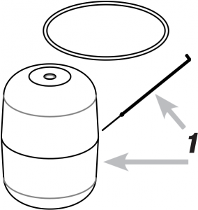
| 1 | FLOAT KIT | 60038-WYN1 |
| 2 | TRANSFORMER | 60194-WYN1 |
| 3 | BACK UP SWITCH | Call for part |
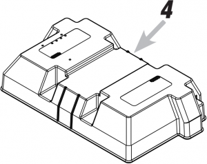
| 4 | LID ASSEMBLY | 60184-WYN1 |
FOR REPLACEMENT PARTS OR CUSTOMER SUPPORT,CALL 1-800-237-0987
ADDRESS PARTS CORRESPONDENCE TO:WAYNE Water Systems 101 Production Drive Harrison, OH 45030 U.S.A.
Please provide following information:– Model number– Serial number on cord tag (not to be removed)– Part description and number as shown in parts list
Thank you for making Wayne Water Systems a key part of your home maintenance program. If properly installed, maintained and operated in accordance with Wayne Water Systems’ written instructions, your pump should provide you with approximately ( * ) years of service.
Product Warranty ( * ) Expected Life
1 32 33 65 6
LIMITED WARRANTY
For three years for WSS30Vn from the date of purchase, from an authorized dealer, Wayne Water Systems will repair or replace, at its option for the original purchaser, any part or parts of its Sump Pumps or Water Pumps (“Product”) found upon examination by Wayne Water Systems to be defective in materials or workmanship. Please call Wayne Water Systems (800-237-0987) for warranty instructions. Be prepared to provide the model number and the serial number when exercising this warranty. All transportation charges on Products or parts submitted for repair or replacement must be paid by purchaser. This Limited Warranty is not transferable. This Limited Warranty does not cover Products which have been damaged as a result of accident, abuse, misuse, neglect, improper installation, improper maintenance, or failure to operate in accordance with WAYNE’s written instructions.
This Limited Warranty does not cover Products which have been damaged as a result of accident, abuse, misuse, neglect, improper installation, improper maintenance, or failure to operate in accordance with Wayne Water Systems’ written instructions.
THIS WARRANTY IS IN LIEU OF ANY AND ALL OTHER WARRANTIES, OBLIGATIONS OR AGREEMENTS, EXPRESSED OR IMPLIED, INCLUDING ANY IMPLIED WARRANTY OF MERCHANTABILITY OR FITNESS FOR ANY PARTICULAR PURPOSE, AND ANY RIGHTS OR REMEDIES AGAINST ANY PERSON OR ENTITY UNDER THE UNIFORM COMMERCIAL CODE OR OTHERWISE WITH RESPECT TO THE SALE OF THE PRODUCT. THE REMEDIES AND OBLIGATIONS STATED IN THIS WARRANTY ARE THE SOLE AND EXCLUSIVE REMEDIES OF AND OBLIGATIONS TO THE OWNER FOR ANY AND ALL MATTERS ARISING WITH RESPECT TO OR IN ANY WAY CONNECTED WITH THE PRODUCT, REGARDLESS OF THE SOURCE OR PROVIDER OF SUCH GOODS. IN NO EVENT, WHETHER AS A RESULT OF BREACH OF CONTRACT, WARRANTY TORT (INCLUDING NEGLIGENCE) OR OTHERWISE, SHALL WAYNE WATER SYSTEMS OR ANY AFFILIATE BE LIABLE FOR ANY SPECIAL, INCIDENTAL OR CONSEQUENTIAL DAMAGES.
You MUST retain your purchase receipt along with this form. In the event you need to exercise a warranty claim, you MUST send a copy of the purchase receipt along with the material or correspondence. Please call Wayne Water Systems (800-237-0987) for return authorization and instructions.
DO NOT MAIL THIS FORM TO Wayne Water Systems. Use this form only to maintain your records.
MODEL NO._____________________ SERIAL NO._________________________ INSTALLATION DATE __________________________
ATTACH YOUR RECEIPT HERE
References
[xyz-ips snippet=”download-snippet”]