
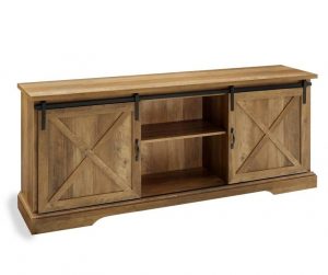
Walker Edison B48SXDEB Assembly Instructions Manual
![]()
Please visit our website for the most current instructions, assembly tips, report damage, or request parts. www.walkeredison.com
General Assembly Guidelines
- Ensure that all parts and hardware are available before beginning assembly.
- Follow each step carefully to ensure the proper assembly of this product.
- Two people are recommended for ease in the assembly of this product.
- The three main types of hardware used to assemble this product are: wood dowels, screws and bolts.
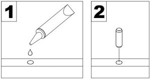
- The provided glue is to secure wood dowels in place. When first inserting dowels, locate the appropriate hole for the dowel, place a small amount of glue in the hole and insert the dowel. Wipe away excess glue immediately.
 In future assembly steps when dowels are necessary to attach assembly parts together, place a small amount of glue on the end of the dowel before attaching parts together. Wipe away excess glue immediately.
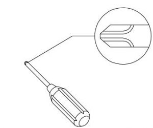
 - A Phillips head screwdriver is required for the assembly of this product.
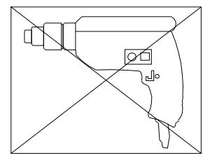
- Power tools should not be used to assemble this product.
- Drill may be needed for securing product to wall.
 In future assembly steps when dowels are necessary to attach assembly parts together, place a small amount of glue on the end of the dowel before attaching parts together. Wipe away excess glue immediately.
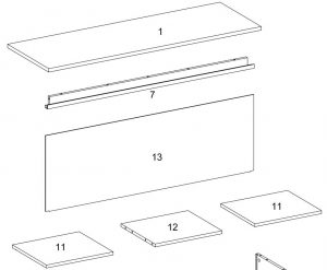
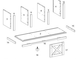
Parts List
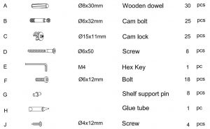
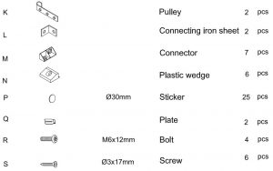
Hardware List
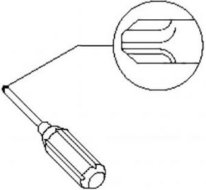 Philips head screwdriver required for assembly (not included)
The hardware quantities listed above are required for proper assembly. Some extra hardware may also have been included.
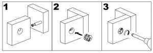
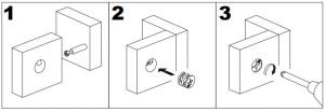
Step 1
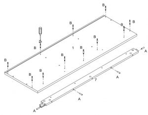
Insert wooden dowel (A) into part (7), then secure cam bolt (B) into part (1) with Philips head screwdriver as per diagram.
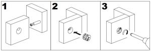
Step 2
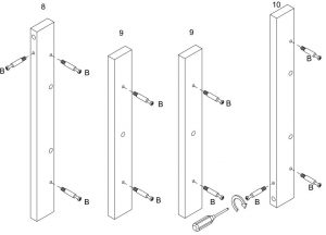
Secure cam bolt (B) into parts (8,9,10) with Philips head screwdriver as per diagram.
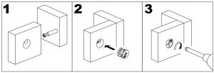
Step 3
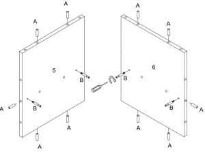
Insert wooden dowel (A) into parts (5,6), then secure cam bolt (B) into parts (5,6) with Philipshead screwdriver as per diagram.
Step 4

Insert wooden dowel (A) into parts (3,4,12) as per diagram.
Step 5
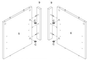
Using cam lock(C) secure part (9) into parts (5,6) with Philips head screwdriver as per diagram.
Step 6

Using cam lock(C) secure part (10) into parts (4) ,part (8) into part (3) with Philips head screwdriver as per diagram.
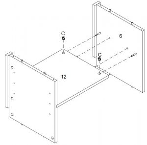
Step 7

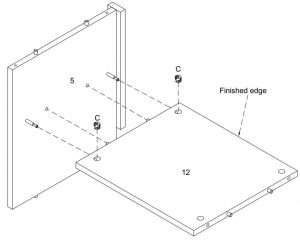
Using cam lock(C) secure part (5) into parts (12) with Philips head screwdriver as per diagram.
Step 8
Using cam lock(C) secure part (6) into parts (12) with Philips head screwdriver as per diagram.
Step 9
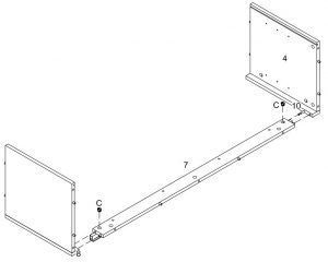
Using cam lock(C) attach parts (8,10) into part (7) with Philips head screwdriver as per diagram.
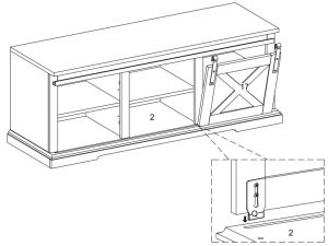
Step 10
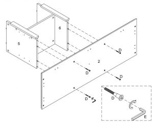
Using screw (D) attach part (2) into parts (5,6) with hex key (E) as per diagram.
Step 11
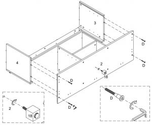
Secure part (18) into part (2),then using screw (D) attach part (2) into parts (3,4) with hex key (E) as per diagram.
Step 12

Using bolt (F) attach connector (M) to parts (14,15,16) with hex key (E) as per diagram.
Step 13

Using bolt (F) attach connector (L) to parts (14,15,16) with hex key (E) as per diagram.
Step 14
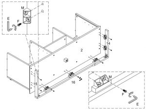
Using bolt (F) attach connector (M) to part (2) with hex key (E) as per diagram.
Step 15

Put part (13) as per diagram.
Step 16

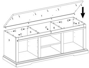
Using cam lock(C) secure part (1) to parts (3,4,5,6,7) with Philips head screwdriver as per diagram.
Step 17
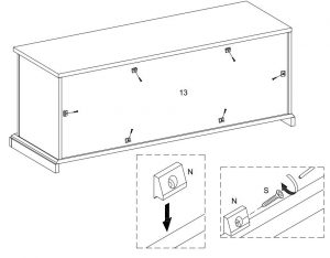
Using screw (S) secure plastic wedge (N) to part (13) with Philips head screwdriver as per diagram.
Step 18

Place sticker (P) cover the holes as per diagram .
Step 19
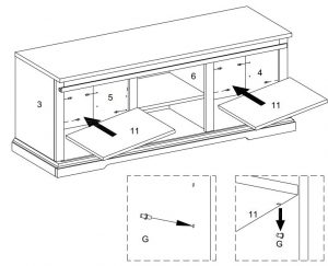
Insert shelf support pin (G) into parts (3,4,5,6) as per diagram. Make sure you place the four shelf support pins (G) in the same level. So the shelf is not titled .Put part (11) into unit as per diagram. Tilt and rest the adjustable shelf(11) onto the shelf support pins .
Step 20
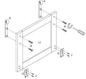
Using bolt (R) secure pulley (K) into part (17) ,then using screw (J) attach plate (Q) into part (17)with Philips head screwdriver as per diagram.
Step 21
Place plate (Q) on door into groove.
Step 22

Hang pulley (K) to part (7), then press down to hold the door.
Step 23

if necessary, adjust the pre-attached Floor Levelers at the bottom to level the unit.
Step 24

Walker Edison B48SXDEB Assembly Instructions Manual – Walker Edison B48SXDEB Assembly Instructions Manual –
Questions about your Manual? Post in the comments!
[xyz-ips snippet=”download-snippet”]