![]()
Series 1 & 2AquaBalance ® CONTROL MODULE QUICK START GUIDE
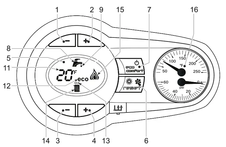
LEGEND
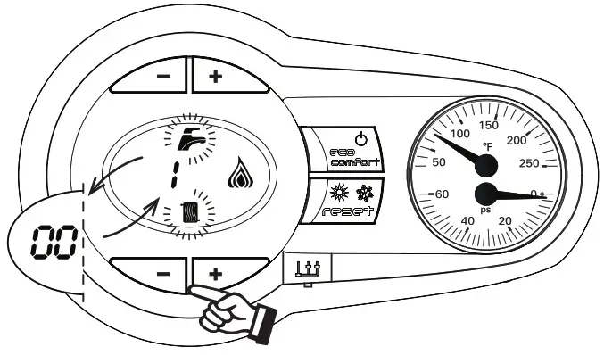
| 1 — Domestic Hot Water temperature setpoint decreasing button2 — Domestic Hot Water temperature setpoint increasing button3 — Central Heating water temperature setpoint decreasing button4 — Central Heating water temperature setpointincreasing button5 — LCD Display6 — Reset / OTC button7 — Economy / Comfort On / Off Power button | 8 — Domestic Hot Water symbol9 — Domestic Hot Water mode operation10 — Multi-function indication (Flashing during heat exchanger protection)11 — Economy symbol12 — Central Heating mode operation13 — Central Heating symbol14 — Burner on and actual load indication(Flashing during flame current supervision)15 — Service tool connection16 — Temperature-Pressure gauge |
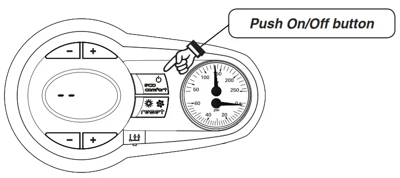
Power On mode
|
System start |
|
| 1 | Push eco /comfort/Power button; to start a boiler |
|
2 |
NOTE: If an A-16 error code is displayed (Central Heating Only boiler) when the unit is powered up, the outdoor sensor is not installed. Install the outdoor sensor and push the reset button to reset the error code. A faulty outdoor sensor will give an “F-39” error code.
The outdoor sensor must be installed unless specifically exempted in the Energy Act statement on page 102 of the AquaBalance boiler manual. |
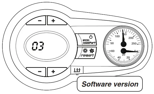
| 3 | 04 “shows on the display” (control software version) |
| 4 | FH “shows on the display” (Blower /inducer operating in purge mode of the combustion chamber and venting for 5 minutes). |
| 5 | With no “call for heat” (current boiler water temperature will be shown in degrees F). |
| 6 | To Change “Central Heating water temperature set-point” (from 68 F to 190 degrees F) use the bottom set of “+” or “–” keys to raise or lower the setpoint temperature. |
| 7 | To change “Domestic water temperature set-point” ( from 104 F to 131 degrees F )NOTE: Ensure that operating temperature is a safe set-point temperature. Use the top set of “+” or “–” keys to raise or lower the setpoint. |
| 8 | To change “Venting material” – see page 7 and boiler manual. |
 |
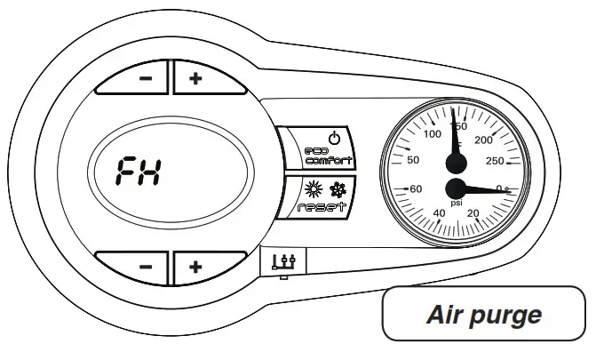 |
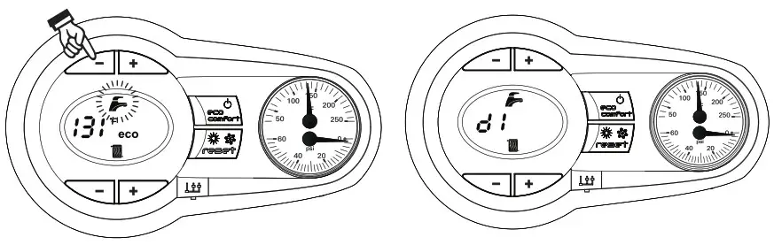
During the first 5 seconds, the display shows the software version of the control module.For the next 300 seconds, the display shows FH that identifies the Air purge function.When the FH disappears, the boiler is ready to function automatically whenever the external controls are calling for heat.
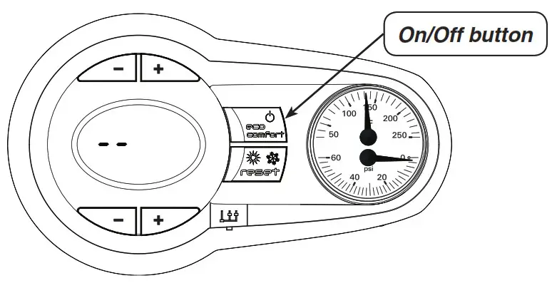 When the boiler is turned off with “eco”/power button, the control module is still powered, heating operation is disabled andthe display is off, however the frost protection will still be active.
To turn boiler on again, press the on/off button (hold for 5 seconds)
The boiler is ready to function automatically whenever the external controls are calling for heat.
Setting Heating Temperature
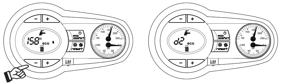
To set the system Heating temperature, use the CH buttons, “-” to reduce water setpoint “+” to increase water setpoint.It can be set from a minimum of 68° F to a maximum of 190° F.
The Central Heating heat demand (generated by the Room Thermostat) is indicated by the flashing of the Hot Air symbol overthe radiator (Items 12 and 13 – pages 1 or 4). The display indicates the actual Central Heating water temperature (Item 10 – pages 1 or 4) and when the required set point temperature is reached “d2” will be displayed.
Setting Domestic Hot Water Temperature
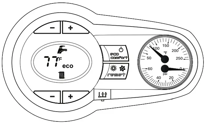
To set the Domestic hot water temperature, use the DHW buttons, “-” to reduce water setpoint “+” to increase water setpoint.It can be set from a minimum of 104° F to a maximum of 131° F.
The Domestic Hot Water heat demand (generated by the DHW flow sensor) is indicated by the flashing of the Hot Water symbol under the tap (Items 8 and 9 – see below). The display indicates the actual Domestic Hot Water temperature (Item 10 –see below) and after Hot set point temperature is reached “d1” will be displayed.
The minimum flow rate to start a DHW call is 0.4 GPM and the flow rate that shuts it off is 0.3 GPM.
Outdoor Reset Control
- When the external outdoor sensor is attached to the boiler, the system can work in Outside Temperature Compensation mode.In OTC mode the temperature of the heating system is controlled according to the external climate conditions, this will insurea high degree of comfort and Energy saving all year round.
- By using the CH buttons (Items 3 and 4) it is possible to set the maximum system water temperature for the installation.
OTC setting
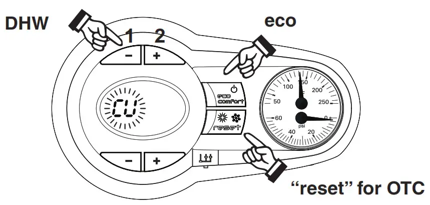
- To enter the OTC – reset mode, press “reset” button for 5 seconds, takes you to Curve menu.
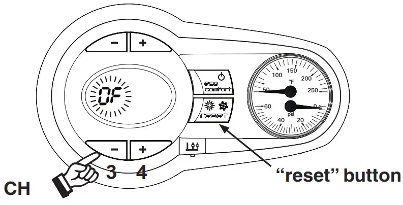
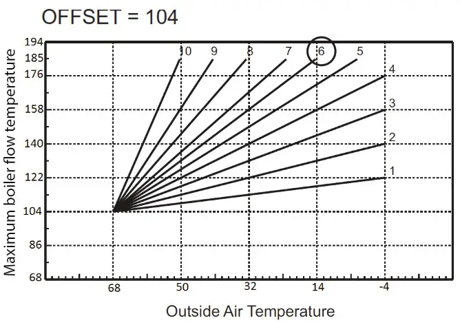
- The display shows “CU” flashing which allows you to adjust the Curve’s value, using the DHW + or – buttons, (items 1 and 2 – above). Select from 1 to 10, in accordance with the charts, Figures 2 or 3, on page 6, or “0”, which means no OTC mode. By pressing the CH push buttons together (Items 3 and 4 – below), the display shows “0F” flashing; to set Offset, use the DHW push buttons (Items 1 and 2 – above). It can be 68 to 104, in accordance with the chart Figure 2 or Figure 3, page 6.

- Switch to OF (Offset mode) by pressing the CH + or – buttons (Items 3 and 4 – above). The display shows “OF” flashing
- The default valve for the Curve is 0, meaning the at no compensation is selected as default.
- The default valve for the Offset is 86.
- To exit the OTC mode, press “reset” button for 5 seconds.
In the case of an outdoor sensor failure, the control will continue to operate the boiler, but without the use of the Compensation Curves, and an error message will flash on the display (Fault 39 – see Troubleshooting section in boiler manual).Upon replacement of the defective sensor the boiler will resume the use of Compensation Curves.
OTC Exempt modeBy pressing the DHW+ and eco buttons together for 10 seconds, it is possible to enter the OTC Exempt menu. The display starts showing the value of the parameter OTC Exempt (See parameter Number 163, page 89 in boiler manual) flashing. By means of the CH – push button it is possible to change value. (Selecting 0 – allows you to Select the Compensation curve for your individual home heating needs). By pressing DHW+ and eco buttons together for 10 seconds, it is possible to leave the OTC Exempt Menu. If no action has been taken, the control automatically leaves this mode after 2 minutes. – 0 = installation non exempt from outside sensor connection; – 1 = installation exempt from outside sensor connection;
Compensation curves – Curve numbers below refer to Figures 1, 2, and 3 – below.
- Curve number 1 is for a high efficiency home with very low heat losses.
- Curve number 6 is for an average home heat losses.
- Curve number 10 is for a home with high heat losses.
Figure 1 Compensation curves reference
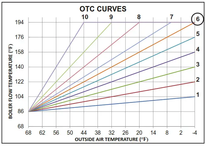
Figure 2 Compensation parallel offset curves – Typical low temperature radiant application such as in-floor tubing.
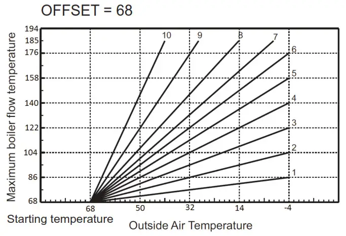
Figure 3 Compensation parallel offset curves – Typical Copper fin tube /cast iron baseboard radiation.
AquaBalance Common Control Prog ramming / Error Codes & Functions Used
- Outdoor sensor A16 (Central Heating Only boiler, should not appear on Combi boilers)• When unit is powered up and no outdoor sensor is connected A16 error code will flash,• Push “reset” button for 1.5 seconds, error code will clear.
- Venting Material Change “b22” (boiler is defaulted for PVC vent material)If other vent material is used, you program that material via the control board.
Control selection for vent material
To insure proper boiler operation, the boiler control programmed default is for PVC venting material. You MUST program theboiler control for any other venting material that you installed other than PVC, in order to improve operational efficiency.Refer to “Control Module Quick Start Guide” page 2, to first power up the boiler.To access the configuration menu:
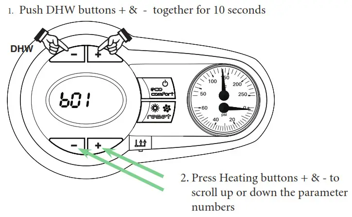
- Press the DHW + and DHW – buttons together for 10 seconds.
- At the end of the ten seconds, the display will show the message “b01”; Use the CH buttons (+ or –) to scroll through parameters. “b01”, then scroll up to “b22”.
 You MUST exit out of ALL of the programming modes when you have finished your vent selection. (see next page)
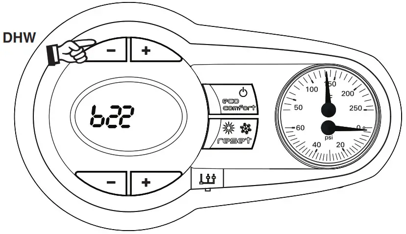
- Press the heating buttons (+ or -) to scroll up the list of parameters in increasing or decreasing order to parameter “b22” Venting Material selection.
- Press the DHW buttons (+ or -) to view or modify the value of a parameter: press the “DHW +” and “DHW -” buttons together for 10 seconds, saves selectionFor example: CPVC, Polypropylene, or AL29-4C stainless steel.PVC solid core, …………………………………… Select: “1” (Default)CPVC only, ………………………………………… Select: “2”Polypropylene and AL29-4C, ………………. Select: “0|
Exiting the “User interface setting” menu. Press the “DHW +” and “DHW -” buttons together for 10 seconds; or switch the power to the unit off and then on again; or wait for automatic exiting which occurs after two (2) minutes
- Boiler “Test Mode” Operation• Used to check combustion parameters when checking Natural Gas fuel combustion and when adjusting combustion parameters for LP fuel conversion.• Pages 63 and 64 in the boiler manual.• If you hear water gurgling, sloshing and / or air in the combustion chamber area (heat exchanger tubing) the boiler needs to be purged of that air to operate properly.• Another indication of air in the heat exchanger would be the boiler will not stay in this test mode on high fire. (this can also happen if the boiler is not piped in the correct size, wrong pump or speed selected (Internal circulator switch set to High) and not piped “primary-secondary” causing flow issues).• The boiler must be completely piped-up with all zones in operation to be able to handle the boiler heating load of maximum fire operation.
Test Mode OperationProceed to put the boiler into operation as follows:
- To operate the boiler in test mode, press the CH “-” and “+” keys together for 5 seconds (See below) to activate the “TEST” mode.
- The boiler lights at the maximum heating 100% rate displayed on the display.
- The high fire (large) flame symbol will be displayed once the boiler has lit.
- Use DHW “-” button to drop firing rate to low fire.
- To exit the “TEST” mode, press the CH keys (Items 3 and 4 – front page or page 5) together for 5 seconds, or leave the boiler to automatically switch off after 15 minutes or stopping DHW flow.
- This TEST procedure is used to check/adjust combustion CO and CO2 per specifications Figure 84, page 63 and Figure 87, page 64 in the AquaBalance boiler manual.
Fuel Conversion to LP Fuel
- With boiler in standby mode, press the DHW + & – buttons together for 10 seconds……….the display will flash “b01”
- Press the DHW + button….. to select ”01” value, which is LP fuel. (Factory default “0” is Natural gas)
- LP fuel conversion steps must be completed per this instruction and the boiler manual.New replacement control boards out of the box are factory programmed for a 120-N-C (combi boiler) and specific parameters MUST be set for any other boiler model that the control board is installed in. (See chart below).
- Press the Heating + button to scroll to parameters b01 to b12 and verify the setting per the “Default Control Board”parameter listed below and make appropriate changes if required. NOTE: specific boiler model has particular operationalparameters per Figure 102 in the appropriate boiler manual or Table 1 for Series 1 or Table 2 for Series 2.
- Press the DHW + or – buttons to “modify the value”.
- Press the DHW + and – buttons together for 10 seconds to exit the programming mode.
Table 1 Default Control Board “Transparent Parameters” for AquaBalance ® Series 1 boilers.
| Boiler Model | “b01” | “b02” | “b04” | “b05” | “b06” | “b10” | “b12” | “P01” | “P02” | “P04” |
| Gas type | Boiler type | Fan Max. Freq. in DHW | Fan Max. Freq. in CH | Fan Min. Freq. in CH | S/W mode selection button | Var. Out Relay | Ignition level | CH Slope (F/min) | CH
Off Time |
|
| WMB-80-N-C | 0=Nat. gas | 3 | 155 | 155 | 40 | 1 | 0 | 80 | 6 | 2 |
| WMB-120-N-C | 0=Nat. gas | 3 | 200 | 200 | 40 | 1 | 0 | 60 | 6 | 2 |
| WMB-155-N-C | 0=Nat. gas | 3 | 205 | 205 | 39 | 1 | 7 | 60 | 6 | 2 |
| WMB-80-N-H | 0=Nat. gas | 2 | 155 | 155 | 40 | 1 | 0 | 80 | 6 | 2 |
| WMB-120-N-H | 0=Nat. gas | 2 | 200 | 200 | 40 | 1 | 0 | 60 | 6 | 2 |
| WMB-155-N-H | 0=Nat. gas | 2 | 205 | 205 | 39 | 1 | 0 | 60 | 6 | 2 |
| WMB-80-LP-C | 1=LPG | 3 | 145 | 145 | 40 | 1 | 0 | 80 | 6 | 2 |
| WMB-120-LP-C | 1=LPG | 3 | 185 | 185 | 40 | 1 | 0 | 60 | 6 | 2 |
| WMB-155-LP-C | 1=LPG | 3 | 200 | 200 | 40 | 1 | 7 | 60 | 6 | 2 |
| WMB-80-LP-H | 1=LPG | 2 | 145 | 145 | 40 | 1 | 0 | 80 | 6 | 2 |
| WMB-120-LP-H | 1=LPG | 2 | 185 | 185 | 40 | 1 | 0 | 60 | 6 | 2 |
| WMB-155-LP-H | 1=LPG | 2 | 200 | 200 | 40 | 1 | 0 | 60 | 6 | 2 |
5. P01 and P02 Control Parameters Fuel
|
Boiler Model |
“b01” | “b02” | “b04” | “b05” | “b06” | “b10” | “b12” | “b22” | “P01” | “P02” | “P04” |
| Gas type | Boiler type | Fan Max. Freq.
in DHW |
Fan Max. Freq.
in CH |
Fan Min. Freq.
in CH |
S/W mode selection button | Var. Out Relay | Vent material | Ignition level | CH Slope (F/min) | CH
Off Time |
|
| AB-80-N-C | 0=Nat. gas | 3 | 155 | 155 | 35 | 1 | 0 | 1 | 80 | 6 | 2 |
| AB-120-N-C | 0=Nat. gas | 3 | 200 | 200 | 40 | 1 | 0 | 1 | 60 | 6 | 2 |
| AB-155-N-C | 0=Nat. gas | 3 | 210 | 210 | 39 | 1 | 7 | 1 | 50 | 6 | 2 |
| AB-80-N-H | 0=Nat. gas | 2 | 155 | 155 | 35 | 1 | 0 | 1 | 80 | 6 | 2 |
| AB-120-N-H | 0=Nat. gas | 2 | 200 | 200 | 40 | 1 | 0 | 1 | 60 | 6 | 2 |
| AB-155-N-H | 0=Nat. gas | 2 | 210 | 210 | 39 | 1 | 0 | 1 | 50 | 6 | 2 |
| AB-80-LP-C | 1=LPG | 3 | 145 | 145 | 35 | 1 | 0 | 1 | 80 | 6 | 2 |
| AB-120-LP-C | 1=LPG | 3 | 185 | 185 | 40 | 1 | 0 | 1 | 60 | 6 | 2 |
| AB-155-LP-C | 1=LPG | 3 | 220 | 220 | 40 | 1 | 7 | 1 | 50 | 6 | 2 |
| AB-80-LP-H | 1=LPG | 2 | 145 | 145 | 35 | 1 | 0 | 1 | 80 | 6 | 2 |
| AB-120-LP-H | 1=LPG | 2 | 185 | 185 | 40 | 1 | 0 | 1 | 60 | 6 | 2 |
| AB-155-LP-H | 1=LPG | 2 | 220 | 220 | 40 | 1 | 0 | 1 | 50 | 6 | 2 |
- P01 parameter (ignition level) as well needs to be changed upon the installation of a new control board. To access the “tS”(Transparent Parameters section) follow the steps below.
- P02 parameter (Central Heating Slope) in some cases is too aggressive depending on particular installations, and can be“user / field adjusted” to 6….a less aggressive temperature ramping to boiler water “set-point”.
- To access the “Transparent Parameters” menu. Press the “reset” button for 20 seconds.
- At the end of 20 seconds the display will show the message “tS”.
- Press the “reset” button for 1 second.
- The display will show the message “P01”.
- Press the Heating buttons to scroll the list of parameters increasing and decreasing order. Press DHW buttons to view ormodify the value of a parameter: the modification will be automatically saved.
- Set the parameter value for “P01” and “P02” to value show in Figure 102 above, according to your boiler model.
- Exiting the “Transparent Parameter” menu. Press the “reset” button for 20 seconds; or wait for automatic exiting which occurs after fifteen (15) minutes.
Boiler Operation “In Safe Mode”
- All boilers have a protection mode, where the controls / sensors look at flue exhaust temperatures to insure that they arewithin correct safe operational values. When they exceed that temperature / value the boiler ramps down the firing rate tolow fire and approximately 130 – 140 degrees central heating boiler water temperature. The boiler will stay in that rangeuntil the call for heat by the T Stat is removed momentarily or the boiler is powered by the plug.
- See the following on how to identify that “safe mode” operation and corrections.
Key Questions to ask …when the boiler “seems to be in a low firing rate” (Will not ramp up to high firing rate)
- Venting length and size, per manual ……did they use LONG sweep elbows ?This is VERY important !
- Piping is critical… AB-155C must be FULL 1 inch NO PEX for primary loop unless the fitting are FULL port size.
- Check CH temperature setting and consider reducing it to 180 or lower. (what is the set point ?)
- Change parameter “P02” to 6 (boiler ramp slope) ……was factory set to 11 degrees (which may be too high on some installs).
- Be sure internal pump switch on the combi is set for high speed.
- Change Max exhaust temperature parameter “b16” to 200 (degrees F).
- Change PVC maximum temperature parameter“b23” to 190 (degrees F). To test that this is the problem…..disconnect the T-stat call for heat for 30 seconds.Then restart call for HEAT by the thermostat.If the boiler now ramps up to set point temperature….refer to above questions and corrections. (this confirms that the boiler was locked into the “safety down firing” mode).
- Using an aggressive boiler ramp of 11 (parameter “P02”) and some piping systems as well as user boiler set point of190 degree F, the boiler shoots past that set point and activates the “Safe Mode” protection.
To test that this is the problem…..disconnect the T-stat call for heat for 30 seconds.Then restart call for HEAT by the thermostat.If the boiler now ramps up to set point temperature….refer to above questions and corrections. (this confirms that the boilerwas locked into the “safety down firing” mode).• Using an aggressive boiler ramp of 11 (parameter “P02”) and some piping systems as well as user boiler set point of190 degree F, the boiler shoots past that set point and activates the “Safe Mode” protection.
What is D1, D2 and D3 ?
| Parameter |
Description |
| D1 | After cycle of Domestic water mode, D1 will be displayed. |
| D2 | When required boiler water set – point is reached D2 will be displayed. |
| D3 | After an attempt for ignition, re-trial ignition delay is in effect (D3 is displayed).• Check for proper fuel supply.• Remove and check ignitor for proper gap, 5/32”, replace if disfigured, check combustion setting Natural gas or LP.• Insure condensate is draining properly.• Insure venting size and length are correct and unobstructed. |
- D1….the boiler is / has finished the call for Domestic Water heating, and is in the transition to either standby mode orcentral heating mode.
- D2….the boiler has reached the required water set point, and the firing has stopped / with a call for Central Heating stillapplied by the T-Stat to the boiler. Pumps will continue to operate and the boiler is monitoring the two internal watersensors (return & discharge) waiting for a water “Delta-T” to return…at that time the boiler will re-fire if need be
- D3….the boiler has made 3 tries for ignition and has failed to ignite. A re-trial ignition cycle / delay is in effect for 3 moretries to ignite.
Common Boiler Error Codes
Best methods to evaluate the A01 error code.
- Reset error code by pushing “reset” button on control module for 1.5 seconds.
- New install, have contractor verify the gas supply is purged.A01….”No burner ignition”Probable causes/solutions
- No gas (new install, gas line not purged)
- Ignition / detection electrode fault
- Faulty gas valve
- Insufficient gas supply pressure (Specs: 3.5 to 11 w.c.)
- Dirty heat exchanger/overdue for cleaning and maintenance.
- Condensate trap blocked (or double trapped) DO NOT loop condensate drain hose.
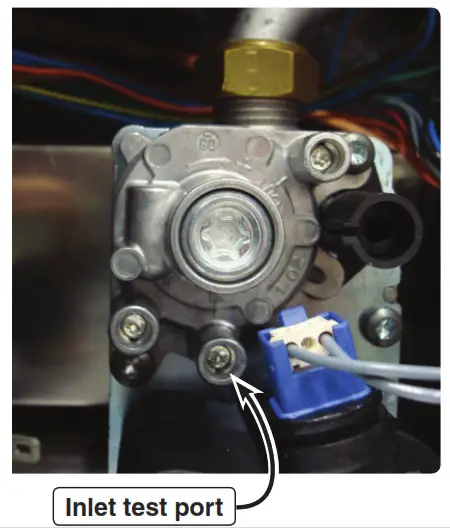
Use a T10 Torx wrench to slightly open the Torx set-screw, slide manometer hose over the set screw housing to read gas pressure while the boiler is firing. Check gas pressure, and securely tighten Torx set screw after testing. (T10 Torx “key” is supplied with the boiler)
To assist in LPG conversion, follow the steps below:Natural gas to LPG conversion
- With boiler fuel supply OFF, follow the installation instructions supplied with the LPG conversion venturi.
- With boiler powered off.
- Install required LPG conversion venturi specific for your boiler model.
- With boiler in “standby mode” no calls for central heating or domestic water heating.
- Insure boiler fuel parameter “b01” is changed to”1” for LPG fuel, Figure 102, pages 10 or 11.
- Adjust gas valve HIGH FIRE screw on right with Allen wrench turn Counter-Clock wise 1-1/8 turns.
- Adjust gas valve LOW FIRE screw on left (remove cover cap with supplied Torx wrench), then turn the screw Counter-Clock wise ¼ turn.
- Replace the gas valve adjustment cover cap and tighten.
- This will adjust your combustion for LPG to be able to run the boiler in the HIGH & LOW fire test mode to further adjust your combustion with your combustion analyzer. See Section 28, “Setting the Air / Gas Ratio”, pages 63-64 in the boiler manual, and follow those instructions.
Checking ignitor gap…… Existing installation:
 report this ad
- Shut off gas supply, remove the ignitor and inspect it for deformities / warped (gap should be 5/32” or the width oftwo nickels which will have a “loose fit”.
- With error code cleared on the control. Carefully drape the ignitor over the plastic control housing being sure that it does not touch anything and restart call for heat / check that the ignitor sparks ? If it does, the control board and ignitor areworking….further investigate gas supply and gas valve.
Existing installation:
- Especially on LP fuel. A warped / deformed ignitor is caused by combustion not properly set per manual for COon “HIGH and LOW fire” as per the manual with combustion analyzer.
- Boiler has “air trapped” within the heat exchanger (listen for gurgling / sloshing noise upon the circulators starting)causing a much higher internal boiler combustion heat condition (where the boiler water is not absorbing the heat ofcombustion) causing the ignitor to overheat. F07….. “High Exhaust Temperature”The exhaust probe detects a higher than normal flue gas temperature of 176 degrees F for PVC vent material.• Check for air in boiler heat exchanger, listen for sloshing / gurgling noises when pump starts. Boiler must be purged ofair entrapped in heat exchanger.• Venting must be checked for proper lengths / long sweep elbows must be installed.• Near boiler system piping not correct size:FULL 1 inch for AB-155C series boilers.• On combi boilers, insure pump selector switch is set to HIGH.• Parameter “P02” (boiler ramp speed) may be too aggressive for particular installation. (“ramp in degrees F per minute”)factory set to 11, set to 6……which is a slower degree rise in boiler water temperature.• Boiler central heating set point set to 190 degrees F, which in some cases (depending on existing heating system pipingand pumps) may be too high, and swing past set point and trip F07 code. Change “user water temp set point” for heating……Set boiler “central heating water” temperature to 175-180 degreesF. F37….”Incorrect system water pressure”• System water pressure to low / code will appear if water pressure is > 8 psi.• Check for system leaking water / water feed valve not refilling system.
Well-McLain 500Blaine Street Michigan City,IN 46360-2388http://www.weil-mclain.cornPart number 550-100-316/0419
[xyz-ips snippet=”download-snippet”]