WEST PENN 8 Button IP Controller
Introduction
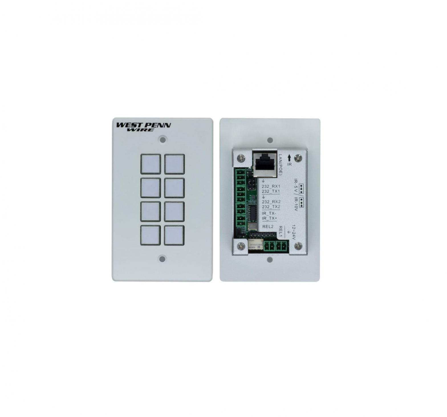
The 8 Button IP Controller (Model: AV-IP-C8-WH) is a versatile wall or table top mounted control panel for West Penn Wire AV over IP devices, select Matrix Switches, and third party products. Each button is programmable. The unit supports one (1) Ethernet port (for TCP/IP and Telnet), two (2) RS-232 ports, one (1) Infrared port, and two (2) Relay ports, for control of end devices. The 8 Button IP Controller can control West Penn Wire products including West Penn Wire’s AV over IP system via the AV-IP-NC811 IP Device Controller, plus TCP/IP, Telnet and RS-232 managed Matrix Switches, as well as third party devices such as projectors and projector screens, displays, AV sources and other similar devices.
The AV-IP-C8-WH supports a web interface, allowing it to be configured and managed via a browser. The web interface allows the unit keys to be programmed individually, supports IR learning and unit configuration.
Panel Description
Front panel view:
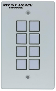
All buttons can be programed to control each TCP/IP, Telnet, RS-232, IR, and Relay controllable end device. Each key supports a removable clear plastic cover, allowing a label to be inserted to reflect the programming of each button.
Rear panel view:
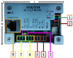
- Power: DC Power Input supporting 12-24VDC ( is recommended)
- Relay #1: An electrically operated switch
- IR output power jumper: jumper left 2 pins for 5V, or right 2 pins for 10V.
- Relay #2: An electrically operated switch
- IR: Infrared radiation digital data output
- Rs232 #2: RS-232 data output
- Rs232 #1: RS-232 data output
- LAN (PoE): LAN port with PoE (PD) power for web interface control
Top panel view:

- IR reader: Learning IR sensor, supporting a frequency of 38KHz
Configuration: Unit Initialization
Before initial use, the user must initialize (factory reset) the AV-IP-C8-WH configuration. To initialize the unit, press and hold the first, third and fifth key as indicated below. Continue to hold these keys while the unit goes through the following illuminated key color sequence, including the lights of these three buttons will turn off, then each of the eight buttons will illuminate (turn on) in red one by one until all are lit, and then they will all flash in green to end the sequence. This sequence is shown below. Note that this restores the factory default settings.

Web Server
The units comes with a factory default IP Address of: 192.168.168.54
To access the unit web server, the user can directly connect a PC LAN port to the AV-IP-C8-WH LAN port with a straight polarity Ethernet cable. After connecting the PC and 8 Button IP Controller, go to the PC network connection section to change the PC’s IP property status to “Static IP” and set the PC IP address to say 192.168.168.178, Subnet Mask to 255.255.255.0 and Default Gateway to 192.168.168.1, as shown below. Once done, open a web browser and enter the IP Address 192.168.168.54 to access to the AV-IP-C8-WH web server.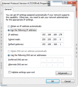
The user must now set the 8 Button IP Controller to the same IP segment as the local area network where the device will be used. To accomplish this go to the Network section via the AV-IP-C8-WH web interface, see below, and set the 8 Button IP Controller IP address accordingly to match the local area network IP Address setting.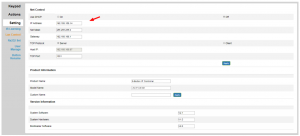
For example if the LAN IP segment is set as 192.168.88.xxx, then set the product IP Address to 192.168.88.1xx. Once the IP Address is set, then the user can access this device in the intended local area network via the AV-IP-C8-WH web interface using the IP Address 192.168.88.1xx (where xx represents the settings selected above).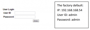
After accessing the 8 Button IP Controller web server, the default user ID is admin, and the password is admin. Login to configure and manage the unit.
After login, go to the Setting Menu to manage LAN, RS-232, IR parameters, User ID and Password, and Button rename.
IR Learning:Please go to the IR Event chapters for further details.
Lan Control / Net Control:Users can set DHCP, IP Address, Subnet Mask, Default Gateway, TCP/IP Server, plus Client and Host IP TCP Port info in the Net Control sub-section, see below.
Lan Control / Version Information:Note that System hardware, boot loader and software version information is listed in the Version information sub-section, see below.
Rs232 Set:
The User can set Rs232_1 and Rs232_2 Baud Rate, Data Bits, Stop bit and Parity settings. The factory default is as shown below.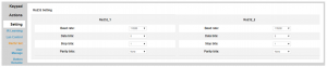
Under the Keypad Menu, the user can click on a virtual keypad to toggle real button functions from within the web interface page. This can be used to test the button programming or to active a button remotely.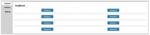
The Actions Menu is where the user programs the button functions. There are 8 buttons to program, where each button supports 2 Modes, 6 Actions, a timer control between each Action, and 11 Events (selection of each Action).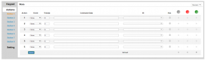
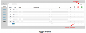
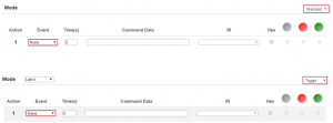
Mode Selection
The 8 Button IP Controller buttons support Standard and Toggle Mode functions.When a button is in Standard Mode, each button press executes the same action.However Toggle Mode supports 2 different actions on the same button, which can be executed alternately with each button press. This is referred to here-in as Release and Latch. The user can also set an Led color (options are off “no color”, red and green) to identify the working mode or command being sent. Toggle Mode is often used as a Turn On and Turn Off function.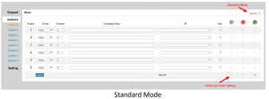
Event Selection
Note: The information here is based on the Standard Mode, but Toggle Mode is supported in the same manner.
The AV-IP-C8-WH supports 11 events as shown below:
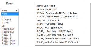
None Event:
Both in Standard and Toggle Mode, the “None” event does nothing, and will clear the Command Data
IR Event:
The User should learned IR codes before using the IR code send function. Go to “Setting \ IR Learning” menu for more details.
How to perform IR Learning:
The system can store 10 IR codes.
|
Input the IR Name, click Learning box, and click Save:
Learning timeout message:
Connect the IR transmitter to the system and select the IR code in the IR pull down menu and click the Submit button.
Example of IR command from pull-down menu: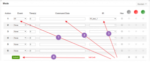
The user can also input the IR code directly into the Command Data area, if known.
Example of IR command entered directly: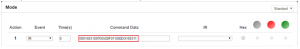
IP_Send Event:
The IP Send Event can send a TCP/IP command or a Telnet command.
Sending a TCP/IP Command:The IP Send Event can send ASCII or HEX character commands to a given IP address. TCP/IP Format: IP address*Port*TCP*Data
Example:To send: 123456789 to IP Address 192.168.168.51The format is: 192.168.168.51*1001*TCP*123456789, ASCII (but do not click on the Hex box), see below.
Sending a Telnet Command:The IP Send Event can send ASCII or HEX character commands to a given IP address. Telnet Format: IP address*Port*Telnet*Data*Login ID*Login Password, where “Login ID” and “Login Password” are optional and should only be used if required by the equipment being controlled. It can take a couple of seconds to send the command, the time that the device log in to the telnet session.
Example:To send: 123456789 to IP Address 192.168.168.51 The format is: 192.168.168.51*23*Telnet*123456789, ASCII (but do not click on the Hex box), see below. In this example “Login ID” and “Login Password” were not used.
IP_Ack Event:The IP Ack Event is used by the 8 Button IP Controller to get feedback from the device being controlled via IP commands, and is used to compare the feedback with predefined data in order to decide whether to continue or stop a given action. If the AV-IP-C8-WH did not get any feedback, it will auto resend data up to 5 more times. If there are many IP_Send events in the system, the IP address and port of the IP_Ack event will relate to the previously sent IP_Send event. Therefore make sure there is a IP_Send event before each IP_Ack event. Note: The IP_Ack is only valid for the TCP/IP command not the Telnet command.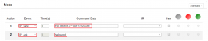
IP Button Trigger Command: >BtnX<cr>
The IP command is a command that allows many 8 Button IP Controllers to work together. It can trigger another 8 Button IP Controller unit to execute a button event.
Command: >BtnX<cr> Where X represents the button number from 1 to 8, and is HEX 0D
For Example: Send IP command “>Btn3” to another AV-IP-C8-WH unit with IP address: 192.168.168.100, in order to trigger IP address 192.168.168.100, Port 1001 of that AV-IP-C8-WH controller Button 3 event.
- Select IP_Send event
- Input 192.168.168.100*1001* 3E 42 74 6E 33 0D , in the Command Data area and click the Hex box (since 3E 42 74 6E 33 0D is the Hex code for: >Btn3)
- Click the Submit Button
The IP_Send event, IP_Ack event, and IP Button Trigger Command are the main commands typically used for IP control. The user can build up flexible IP control applications by making efficient use of them.
LED Event:
LED Event allows the user to setting/change the button LED color. The system supports LED off, LED color Green and LED color Red options. The user can select an LED Event and then select the input button number (within the Command Data area), and then select the LED event color on the far right side.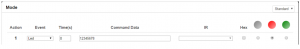
Relay1_NO/Relay2_NO Event:
The 8 Button IP Controller relay port may be connected to a DC power supply or voltage source of up to 24VDC, and to a device which the user wishes to control via this voltage (or to another relay to control higher voltage systems). The contact relay of the AV-IP-C8-WH is normally open (NO). Select event Relay (such as Relay1_NO) and press Submit, as shown below.
Once the command is sent (submitted), the Relay is then closed until it is pressed again, where it will reopen. This function works as a toggle switch (regardless on the mode setting), such that each time the command is sent via the assigned button the relay state changes from open to close or close to open. This is true even for “Standard” mode.

RS232_1/RS232_2 Event:
The user can choose either the Rs232_1 or Rs232_2 port to send RS-232 data. The factory RS-232 setting is: Baud rate 115200, Data bits 8, Stop bits 1, and no-Parity bits.
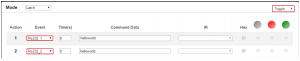
Standard Mode:Select Standard Mode from the pull-down box. When pressing a button in this mode, the AV-IP-C8-WH controller will send the command data through the RS-232 port as shown below.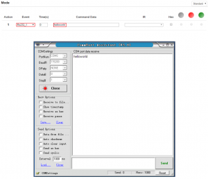
Hex: By pressing the Hex selection box, the user can type Hex data in the Command Data field of the AV-IP-C8-WH Controller, which will then send this Hex data out through the AV-IP-C8-WH RS-232 port.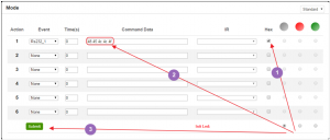

Note: Same operations support Toggle Mode, but Toggle Modes must be selected as shown below.
Rs232_1Ack and Rs232_2Ack Event:Rs232_1Ack and Rs232_2Ack Events are used to allow the AV-IP-C8-WH controller to get feedback from RS-232 devices, and to compare the feedback string with predefined data to decide whether or not the action (operation) should continue or be stopped. If the controller did not receive any feedback, it will auto resend the data up to 5 times. Make sure that there is an Rs232 event before an Rs232_Ack event.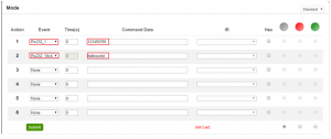
IP pass through RS-232 Command:The IP pass through RS-232 command allows users to send data from IP to RS-232 or vis-versa. This means that the AV-IP-C8-WH controller can function as a control repeater.>CSNumTXMsgWhere “Num” can be: “0” for LAN, “1” for Rs232 port 1, and “2” for Rs232 port 2 “Msg” is: The pass through Data and is 0D in HEX
For Example: to send “Hello” from RS232 to LAN, the Hex code is: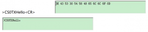
For Example: to send “world” from LAN to RS-232 port 1, the Hex code is: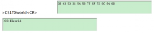
Time(S) Application:
Each button can execute up to 6 events. A time delay between each event can be set. Time(S) is the time delay set between 2 events (in seconds), see below.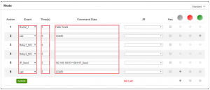
Update Firmware
Connect the AV-IP-C8-WH Controller to a PC with a network cable.
Press and hold the first and the last button (button 1 and 8) on the AV-IP-C8 WH, and while hold these buttons pressed connect the power supply (with power) to the AV-IP-C8-WH. The IP Device Controller will enter boot loader mode and each LED will flash green starting from the first to the last button. Open the Boot Loader software available on the West Penn Wire website under the AV-IP-C8-WH webpage and type the IP address and TCP Port of the AV-IP-C8-WH Controller (default is: IP Address 192.168.168.54 and port 1001), as shown below.
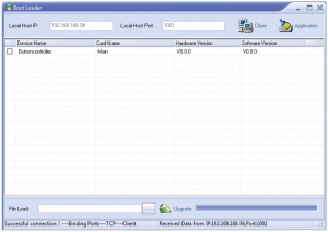
Click the AV-IP-C8-WH Controller and select the new firmware file to upload, and then click Upgrade. Please wait for the upgrade process to complete.
To finalize the upgrade process, restore factory settings by holding the first, third and fifth button at the same time, and the Upgrade will succeed.
Safety Information
 To reduce the risk of electric shock, do not expose this product to rain or moisture
 Do not modify the wall plug. Doing so will void the warranty and safety features
 If the wall plug does not fit into your local power socket, hire and electrician to replace the socket or purchase an adapter.
 This equipment should be installed near the AC outlet and the device should be easily accessible in case power needs to be quickly disconnected.
Warranty
This product has a two (2) year warranty from the date of original purchase.
The warranty will be void if a serial number has been removed from the product.
Upon determination of a legitimate defect covered by this warranty and at West Penn Wire’s sole discretion, the unit will be either repaired or replaced. The user must bear the transport cost to West Penn Wire, and West Penn Wire will bear the return cost of the shipment during the warranty period.
If product is out of warranty then a repair charge will be applicable.The repair cost will be determined on a case-by-case basis. West Penn Wire will repair the faulty out of warranty product after the repair cost has been approved by the Customer and proper financial arrangements are agreed upon. The customer must bear all shipment costs for out of warranty products, including to and from West Penn Wire.

[xyz-ips snippet=”download-snippet”]