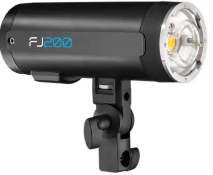
Westcott FJ200 Round Head Pocket Strobe
Included Components & Overview
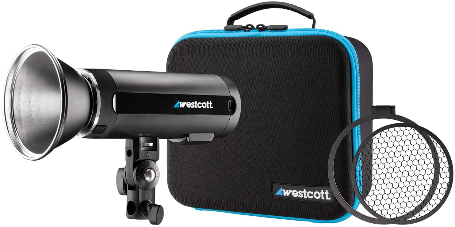
FJ200 Strobe, Lithium Polymer Battery, Battery Charger, Flash Tube Cover, T ilter Bracket, Metal Reflector (5″), 30° Honeycomb Grid, Diffusion and Color Gel Set, Grid & Gel Clip, USB-A to USB-C Cable, Travel Case.
Introduction
This guide covers setup, controls, and basic operation. Visit fjwestcott.com/4740 and scroll to the Support section to download the complete FJ200 User Manual.
Warning
- IMPORTANT: During operation, the flash tube, LED modeling lamp, and select components of the FJ200 Strobe temperatures will increase. Please use caution while using to avoid serious burns or injuries.
- Use only with the Westcott FJ200 Lithium Polymer Battery and/or AC Power Adapter and Cord (sold separatley).
- Do not touch the flash tube, LED modeling lamp, metal reflector, metal snoot, and other metal components and accessories after immediate use to avoid potential injury.
- Never leave unattended around children and/or pets.
- Keep away from fire, water, and moisture.
- Do not submerge in water.
- Avoid drastic temperature changes before, during, or after use.
- Avoid direct skin contact with the flash tube and LED modeling lamp when replacing the flash tube.
- Always remove the FJ200 Lithium Polymer Battery from the FJ200 Strobe during travel/storage to avoid accidental operation which could lead to overheating or permanent damage.
- Do not overtighten tilter bracket tension knobs.
- Ensure the FJ200 is securely mounted before use.
- Only use FJ200 compatible modifiers and accessories and ensure they are securely attached to the FJ200 Strobe before use.
- Do not attempt to modify any Westcott products. Contact Westcott for assistance.
- The maximum operating temperature is 14-104° F (-10-40°C).
Dual-Stage Heat ProtectionThe FJ200 is equipped with a self-monitoring system ensuring safe operation during continued full power use during a short timeframe. The monitoring system provides a staged automatic shutoff scenario:
- Stage 1: Once the strobe reaches an internal operating temperature of 131° F (55°C) the screen will display a red Bulb Icon and the recycle time will increase to 2 seconds in efforts to cool the unit while allowing for further operation.
- Stage 2: Once the strobe reaches an internal operating temperature of 167° F (75°C) the screen will display a red OH icon and the unit will be inoperable for an estimated 10 minutes until an adequate internal temperature has been reached to continue operation.
- Once the unit has cooled, the OH will disappear from the screen and it will then be safe to continue operation.
Getting Started
Charging the FJ200 Lithium Polymer Battery
- Ensure the FJ200 is OFF by long-pressing the Power I Test button until the LCD screen turns off.
- Remove the battery from the FJ200 by sliding the release towards the rear of the FJ200 while gently pulling the battery away from the strobe body.
- Connect the FJ200 Charger Power Cord to the FJ200 Battery Charger and plug the cord into a wall outlet. Wait until the AC Power LED indicator light turns red and the four battery LED indicators to turn green before inserting the battery.
- Align the gold contacts on the bottom of the FJ200 battery with the pins inside the charger. Insert the battery into the charger and gently press down until the battery locks into place.
- The battery is charged and can be safely removed from the charger when all four battery LED indicators are full and stopped blinking.
- Remove the battery from the charger by grasping the sides and pulling away from the charger.
Battery Charger LED Indicator Light Colors:
Solid Red & Solid Green:
- No Battery Inserted: The charger is plugged into a power outlet and ready to charge the FJ200 Battery.
- Battery Inserted: The FJ200 Battery is fully-charged and ready to be removed from the charger.
Solid Red & Blinking Green:
- Battery Inserted: The FJ200 Battery is successfully docked and charging.
Attaching the FJ200 Lithium Polymer Battery
Attach the FJ200 battery into the strobe by aligning the metal contacts on the bottom of the battery to the pins inside the FJ200 battery compartment, slide the battery release on the FJ200 toward the rear of the unit and gently press the battery into the battery compartment until it clicks into place.
DC Power Operation
- Ensure the FJ200 battery has been fully charged and the battery is inserted in the FJ200.
- Turn the strobe ON by pressing and holding the Power I Test button until the start-up screen appears. Release the Power I Test button.
AC Power Operation
AC operation requires the FJ200 AC Adapter (SKU#4749) sold separately.
- Ensure the FJ200 strobe is OFF.
- Remove the battery from FJ200.
- Insert the 2-pin power cord in the FJ200 AC Adapter.
- Align the metal contacts on the bottom of the AC Adapter to the pins inside the battery compartment. Gently press the AC Adapter into the compartment until it clicks into place.
- Plug the 2-prong connector into a standard wall outlet. (Note: Ensure that all electrical components are compatible with the country being used.)
- Turn the strobe ON by pressing and holding the Power I Test button until the start-up screen appears. Release the Power I Test button.
Mounting
Mounting to a Light Stand
- Attach the tilter bracket to the FJ200 by attaching the 1/4″-20 thread located on the tilter bracket’s locking dial to the bottom of the FJ200. (Note: The curved side of the tilter bracket platform equipped with the 1/4″-20 should face forwards.)
- Rotate the tilter bracket’s locking dial clockwise until it’s securely affixed to the base of the FJ200. (Note: Do not overtighten.)
- Rotate the tilter bracket’s tension knob counterclockwise until the light stand receptacle is perpendicular to the strobe body. Retighten by turning the knob clockwise.
- Loosen the tension knob located lower on the tilter bracket.
- Insert the light stand spigot into the FJ200’s 5/8″-16 mm tilter bracket receptacle.
- Tighten the tension knob to secure the strobe to the light stand. (Note: Do not overtighten.)
Attaching & Removing Modifiers
Connecting the FJ200 Metal Reflector & Compatible Modifiers
- Remove the FJ200’s Flash Tube Cover by sliding the adapter release towards the product logo, rotate the flash tube cover counterclockwise and pull away from the FJ200.
- Grasp the FJ200 Metal Reflector (or compatible FJ200 modifier) and align its four square mounting blocks with the openings located on the face of the strobe.
- Insert the reflector or modifier and rotate clockwise until it locks into place.
Removing the FJ200 Metal Reflector & Modifiers
1. Ensure the strobe is turned OFF and has cooled for five minutes.2. With caution grasp the FJ200 Reflector or modifier.3. Slide the strobe’s adapter release away from the modifier.4. Rotate the reflector or modifier counterclockwise until the four square mounting blocks align with the adapter openings and gently pull the modifier away from the strobe to remove.
Attaching an Umbrella-Based Modifier
1. Ensure the strobe is turned OFF and has cooled for five minutes.2. Grasp the umbrella’s shaft and slide into the strobe’s umbrella receptacle located on the tilter bracket.3. Slide the umbrella into the desired position.
Note: Due to the compact design of the FJ200, the removable tilter bracket is not equipped with an umbrella tension screw. When using umbrella based modifiers, avoid tilting the FJ200 at an angle that may cause the modifier to slide out of the bracket, resulting in potential damage to the product, individuals, and/or the surroundings.
Removing an Umbrella Based Modifier
1. Ensure the strobe is turned OFF and has cooled for five minutes.2. Grasp the umbrella’s shaft and gently slide the umbrella out of the FJ200 umbrella receptacle.
Note:
• Never force entry or removal of modifiers and/or umbrellas.• Use caution during the removal of modifiers to not damage the flash tube.• Octagonal and larger umbrella shafts greater than 8mm will not fit into the FJ200 umbrella receptacle.
Updating Firmware
The FJ200 strobe is designed with a USB-C port to allow for firmware updates only (no charging). Future firmware updates could result in performance enhancements, modified menu options and menu layouts. It is strongly suggested that you visit fjwestcott.com/4740 to confirm your strobe has the latest firmware.
Installing the Firmware
- Visit fjwestcott.com/4740 and scroll to the Support section. Find and download the latest firmware ZIP file. (Note: Various browsers may automatically unzip the ZIP file. In this scenario, skip to Step #3.)
- Unzip the file and open the extracted folder.
- IMPORTANT: Read ALL FILES located in the extracted folder (i.e. README, Changelog).
- Ensure the FJ200 is OFF and cooled before removing the battery from the strobe.
- Connect the USB-A to USB-C cable to the FJ200’s USB-C port.
- Common operating systems will present the strobe as an external drive device.
- Locate the .BIN file on your computer and drag the file to the FJ200 (external device). (Note: The file ending in .BIN will be the ONLY filed copied to the FJ200.)
- Once the file has been completely copied to the FJ200, EJECT the FJ200 from the computer.
- Remove the USB-C cable from the FJ200 and reinsert the battery.
- Long press the Power I Test button on the FJ200 to initiate the firmware update and confirm installation was successful by locating the firmware text in the bottom right corner of the screen during the start-up process.
IMPORTANT
- It’s recommended that the firmware update installation process be completed only when the connected computer’s power level is ;,: 50%. Loss of power of any type during this process could render the FJ200 inoperable and require professional repair.
- Removing the USB-A to USB-C cable from the FJ200 without properly ejecting the FJ200 from your computer could render the strobe inoperable and require professional repair.
- Depending on the operating system and the applications running, copying the firmware from your computer to the FJ200 may take a few minutes and/or halt the copying process. Should this happen, close the copy progress window and try again. Further copying issues may require the computer to be restarted.
Warranty
Westcott’s warranty obligations for this product are limited to the following terms.The F.J. Westcott Co. (“Westcott”) warrants this Westcott branded product against defects in materials and workmanship under normal use for a period of ONE (1) YEAR from the date of retail purchase from Westcott or an authorized retailer by the original end-user purchaser (“Warranty Period”). If a defect arises and a valid claim is received within the Warranty Period, at its option and to the extent permitted by law, Westcott will either (1) repair the defect at no charge, using new or refurbished replacement parts, or (2) exchange the product with a product that is new or which has been manufactured from new or serviceable used parts and is at least functionally equivalent to the original product. This Limited Warranty applies only to products manufactured by or for Westcott that can be identified by the Westcott trademark, trade name, or logo affixed to them.
This warranty does not apply to: (a) damage caused by accident, abuse, misuse, flood, fire, earthquake, mold, or other external causes; (b) damage caused by operating the product outside the permitted or intended uses described by Westcott; (c) a product or part that has been modified to alter functionality or capability without the written permission of Westcott; or (d) cosmetic damage, including but not limited to scratches, dents and broken plastic.
Disclaimer: By purchasing, borrowing and/or using this product for any event, both public or private, you, the customer, accepts all responsibility and releases Westcott, and its associates, of any and all liability in the event of manufacturer’s defect, malfunction or misuse of the product which may lead to further injuries or complications unforeseen by the user. Westcott is not responsible for any potential or incurred damage caused by failure to properly mount, hang, or store the product, which includes, but is not limited to damage to cameras, electronics, electrical equipment, buildings, building materials, personal injury, death, or disability, fire damage, or any and all other damage not mentioned previously.
Please contact Westcott Customer Support for a Return Authorization Number “RMA” prior to requesting warranty service. This RMA must be clearly written on the outside of the box to the left of the shipping label. Items sent in without pre-authorization or that do not fall under the limited warranty will be returned at the expense of the sender.Phone: 800-886-1689 / 419-243-7311 (International)Email: [email protected]Shipping: F.J. Westcott Co, 1425-B Holland Rd. Maumee, OH 43537
Register your new gear online at FJWESTCOTT.COM/REGISTER
 report this ad
Visit WESTCOTTU.COM for videos, pro tips, inspiration, and more!Westcott products are made to the company’s traditionally high standards of quality and comply with all applicable government safety regulations and requirements. In an effort to provide the best quality products possible, we periodically make product modifications. Actual products may not be identical to items pictured. Made in China. ©F.J. Westcott Co. All rights reserved. J1220
[xyz-ips snippet=”download-snippet”]