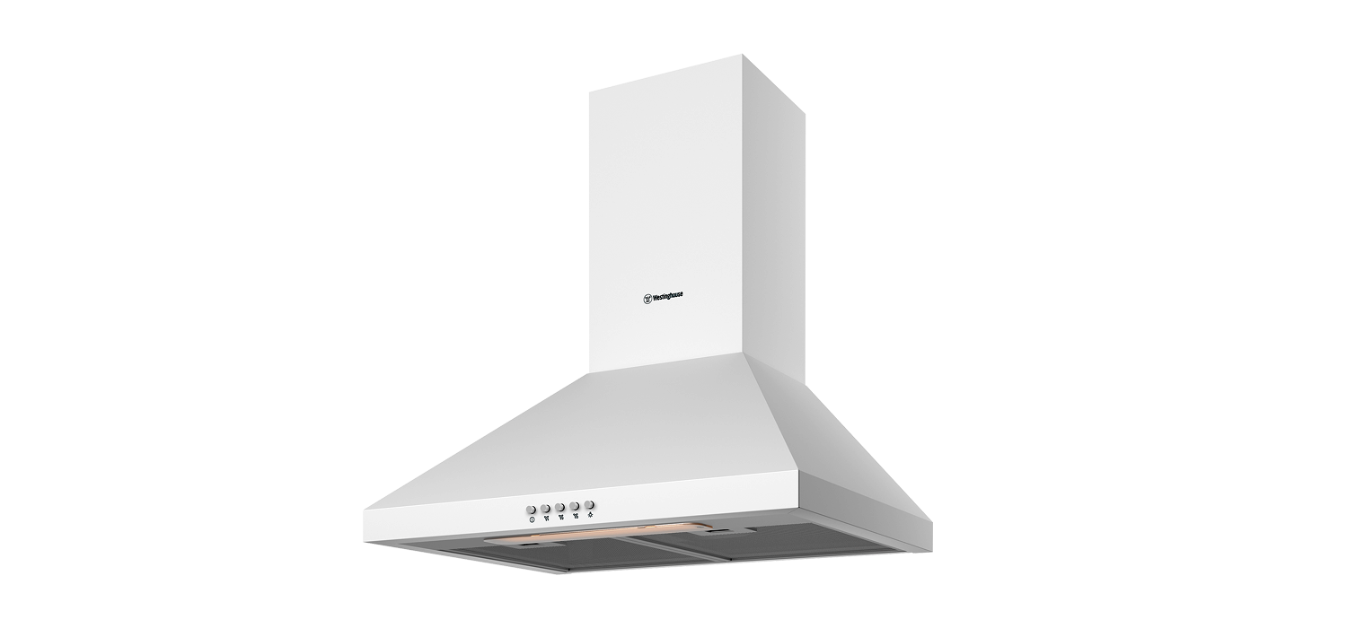
CANOPY RANGEHOOD
Model: WRC604WC
CONGRATULATIONS
Dear Customer,Congratulations and thank you for choosing our canopy rangehood. We are sure you will find your new rangehood a pleasure to use. Before you use your rangehood, we recommend that you read through the whole user manual, which provides the description of the rangehood and its function.
To avoid the risks that are always present when you usean electrical appliance it is important that the rangehood is installed correctly and that you read the Safety instructions carefully to avoid misuse and hazards. We recommend that you keep this instruction booklet for future reference and pass it on to any future owners. After unpacking the hood please check it is not damaged.
If in doubt, do not use appliance but contact your local Electrolux Service centre.
Conditions of use
This appliance is intended to be used in household and similar applications such as:
- Staff kitchen areas in shops, offices and working environments
- Farm houses
- By clients in hotels, motels and other residential type environments
- Bed and breakfast type environments
- Catering and similar non-retail applications
- Please ensure you read the instruction manual fully before you call for service, or a full service fee could be applicable.
Record model and serial number hereModel number:_____________________________________Serial number:______________________________________PNC:_____________________________________________
Please read the user manual carefully and store in a handy place for later reference.
The symbols you will see in this booklet have these meanings:

IMPORTANT INFORMATION THAT MAY IMPACT YOUR MANUFACTURER’S WARRANTYAdherence to the directions for use in this manual is extremely important for health and safety. Failure to strictly adhere to the requirements in this manual may result in personal injury, property damage and affect your ability to make a claim under the Westinghouse manufacturer’s warranty provided with your product. Products must be used, installed and operated in accordance with this manual.
You may not be able to claim on the Westinghouse manufacturer’s warranty in the event that your product fault is due to failure to adhere this manual.
IMPORTANT SAFETY INSTRUCTIONS
Warning:
- This appliance is not intended for use by persons (including children) with reduced physical, sensory or mental capabilities, or lack of experience and knowledge, unless they have been given supervision or instruction concerning use of the appliance by a person responsible for their safety.
- Children should be supervised to ensure that they do not play with the appliance.
- If the supply cord is damaged, it must be replaced by the manufacturer, itsservice agent or similarly qualified persons in order to avoid a hazard.
- There is a fire risk if cleaning is notcarried out in accordance with the Instructions.
- The air must not be discharged into a flue that is used for exhausting fumes from appliances burning gas or other fuels (not applicable to apMiances Mat oMydischarge the air back into the room)
- Regulations concerning the discharge of air have to be fulfilled.
- CAUTION: Accessible parts may become hot when used with cooking appliances.
Electrical connection
- Check that the mains voltage matches with the voltage on the data plate inside the canopy rangehood.
- Check that the installation complies with standards of local building, gas and electrical authorities. Before connecting to the mains supply ensure that the mains voltage corresponds to the voltage on the rating plate inside the cooker hood.
- If the supply cord is damaged, it must be replaced by the manufacturer or its service agent or similarly qualified person in order to avoid a hazard.
Safety warnings – for the installer
When installing the cooker hood, make sure you adhere to the minimum and maximum distances from the cooker hood base to the hob surface (refer to page 7).
Exhaust flue installation: The following rules must be strictly followed to obtain optimal air extraction.
- Keep exhaust flue short and straight.
- Do not reduce the size or restrict exhaust flue.
- Keep bends in the exhaust flue to a minimum.
- When using flexible flue always install duct with helix pulled taut to minimize pressure loss.
- Failure to observe these basic instructions will drastically reduce the performance and increase the Nosie levels of the cooker hood.
Exhaust air must not be discharged into a wall cavity, unless the cavity is designed for that purpose. The exhaust from the cooker hood must not be discharged into any heating flue, which may carry combustion products from other sources.
NOTE: Some installations may require the telescopic exhaust cover to be cut to length. Cut with sharp tin snips or a fine-tooth hack saw blade, taking care not to distort or dent the exhaust cover.
PRODUCT DESCRIPTION

Additional items required for installation
- Fixings required to attach rangehood body and anti tilt brackets
- Fixings required to attach flue cover mounting brackets
- Worm drive clamps, duct tape or cable ties
- Exhaust ducting, 150mm diameter
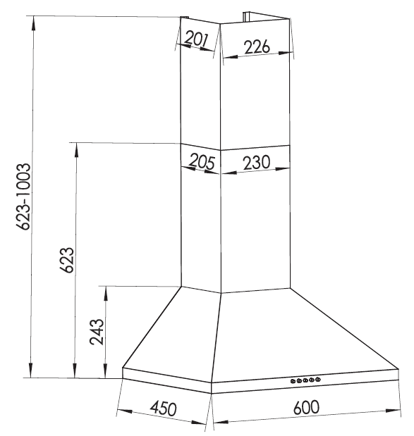
Technical specification
- Power supply: AC 220~240V 50Hz. Connects to 10 A power point
- Lights: 2 2 watt, 240V E14 LED
| MODEL | WRC604WC |
| Height | 623-1003mm |
| Width | 600mm |
| Depth | 450mm |
| Max absorbed power | 200W |
| Lighting | 2 2W E14 LED |
| Outlet diameter | 150mm |
| Electrical connection | 220-240V, 50Hz |
RANGEHOOD DIMENSIONS
INSTALLATION
Pre-installation
Before installing the rangehood, peel off any protective coating and remove the filters.
Location
The hood is to be mounted on the wall. When installed, the hood must be not less than 60cm above electric burners or 65cm above gas or mixed-fuel burners.
DISTANCE FROM HOOD BAST TO TOP OF HOB
| HOB TYPE | MINIMUM | MAXIMUM |
| GAS | 650mm | 800mm |
| ELECTRIC | 650mm | 800mm |
If the instructions of the hob specify a greater distance than the minimum above, then that shall be the minimum height for installation.
Installation
- Using a spirit level mark a vertical centre line on the wall where the hood is to be positioned, and a horizontal line at the hood base position.
NOTE: The height of the underside of the hood body must be a minimum of 600mm* to a maximum height of 800mm.
*If the instructions of the hob specify a greater distance than the minimum above, then that shall be the minimum height for installation.
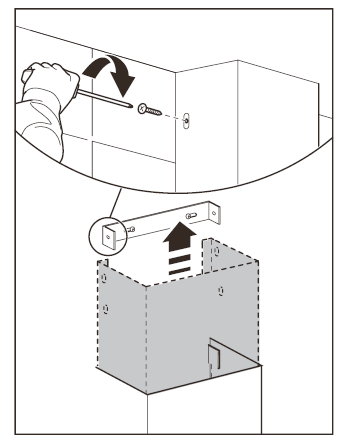
2. Mark the location for the flue cover wall mounting brackets and rangehood mounting points and anti-tilt fixing points above the hood base using the hood base as a reference point.
WARNING: Failure to install the screws or fixing device in accordance with these instructions may result in electrical hazards.
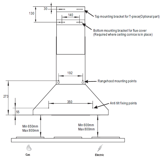
3. Install flue cover wall mounting brackets with suitable fasteners. Suitable fasteners must be used for rangehood mounting points . Refer to Fig.5 for dimensions.
If installation is for recirculation mode refer to Item 6a and Fig.9.

4. Fit the dampers to the exhaust air outlet. Slight bending of the dampers will be required for the fitment
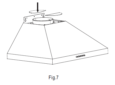
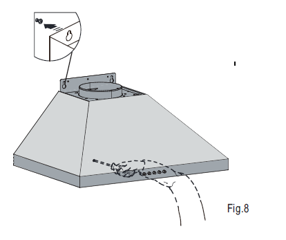
5. Hang the body hood on the mounting screws then secure at the anti-tilt locations(2 places) as indicated in Fig 8.
Depending on the preferred installation/ducting mode, follow step 6a or 6b below.
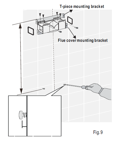
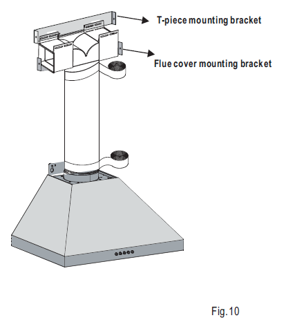
6a. Recirculating mode(Fig.9)
Fix the T-piece to the top mounting bracket by using the 4 screws supplied as dimension indicated Fig 5. Adhere two sponge to the outlet of T-piece. Using the centre line, install the recirculating T-piece and mounting bracket to the wall. Install flexible pipe between T- piece and air outlet Use cable ties or suitable duct tape to secure flexible pipe to T-piece and outlet of the hood.(Fig.10)
NOTE: When installed in recirculating mode, it is recommended to use a charcoal filter to prevent odours being emitted back into the room. For instructions on fitting charcoal filter, please refer to page 11.
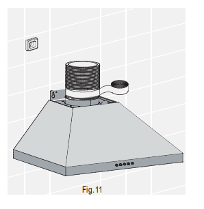
6b. Ducted mode (Fig.11) insert flexible pipe and secure flue tape to air outlet with suitable duct tape.
NOTE: for ducted mode we recommended to extend the flue pipe through the roof cladding(with appropriate flashing) to an external roof cowl, venting the exhaust externally.
To ensure optimum performance of the rangehood, the use of bends should be avoided. Straight, rigid and short ducting is recommended to use. All ducting must be fire retardant.
WARNING: Exhaust air must not be discharged into a wall cavity, unless the cavity is designed for the purpose.
7. Insert the power cord to the power outlet.

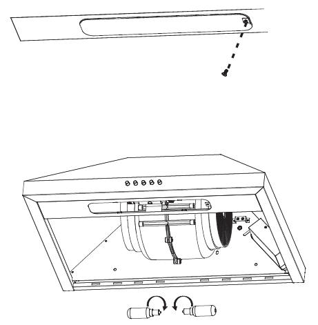
8. Insert the flue cover section to the body hood.

9. Slide flue cover to upper position and fix with screws provided .
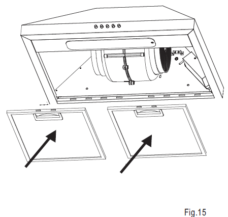
10. Install the filters to the hood.
USING YOUR RANGEHOOD
- Best results are obtained by using a low speed for normal conditions and high speed when odours are concentrated.
- Turn on the hood on a few minutes before you start cooking.
- The hood should be left on for a minimum of 5 minutes after cooking or until all odours have dispersed.
- The control switch are located on the front of the unit. See below
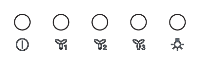
Turning on/off the lampPress button ![]() to turn on the lamp, press
to turn on the lamp, press ![]() once again to turn off the lamp.
once again to turn off the lamp.
Turning on/off the fanPress button ![]() to choose different fan speed according to cooking conditions, press button
to choose different fan speed according to cooking conditions, press button ![]() to turn off the fan
to turn off the fan
NOTE: This product is fitted with a safety cutout device.If the cooker hood is installed too close to the cooktop, flambe cooking, operating the cooktop without cooking utensils and blocked filters may activate the safety cutout device.
CARE & MAINTENENCE
CAUTION:
External surfaces are susceptible to scratches and abrasions, so please follow the cleaning instructions to ensure the best possible result is achieved without damage.
Cleaning the hood
- Clean the outside of the hood using a damp cloth and a solution of water and mild washing up liquid. Clean the surfaces using non-abrasive cleaning products. Use of a soft cloth reduce the risk of scratching. If the cloth is wet ensure that a dry soft cloth is used to wipe down the surface.
- Never use corrosive, abrasive or flammable cleaning products or products containing bleach.
- Never insert pointed objects in the motors protective grid.
- Only ever clean the switch panel and filter grill using a damp cloth and mild washing up liquid.
- It is extremely important to clean the unit and change the filters at the recommended intervals. Failure to do so will cause grease deposits that could cause a fire.
- Clean regularly after use to remove any residues from cooking, especially residues from acidic fruits, yoghurts & milk based products.
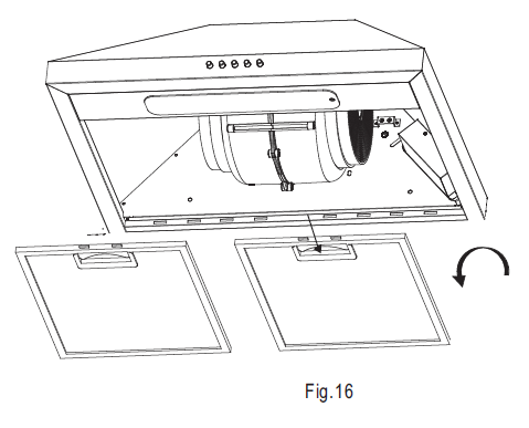
Removing the metal grease filters
- Push the grease filter and then pull it down and out.
Hand washing
Soak grease filter for about one hour in hot water witha grease-loosening cleaner, then rinse off thoroughlywith hot water. Repeat the process if necessary. Refitthe grease filters when they are dry.
Dish washer
Place grease filters in the dishwasher. Select the most powerful washing program and highest temperature, at least 65℃. Repeat the process. Refit the grease filters when they are dry. When washing the metal grease filter in the dishwasher a slight discolouration of the filter can occur, this does not have any impact on it’s performance.
Note: The metal grease filters must be removed and washed, either by hand or in the dishwasher, every four weeks minimum.
- Clean the inner housing using warm water and grease loosening cleaner(never use caustic detergents, abrasive powders or brushes).
WARNING:
Ensure that the appliance is switched off before cleaning inner housing to avoid any possibility of electric shock.
Charcoal filter
- The charcoal filter should only be used if you want to use the hood in the recirculation function.
- This filter cannot be cleaned or re-used and as a general rule, the activated charcoal filter should be changed once every four months.
Fitting charcoal filter
Fit one charcoal filter on the left and one on the right so as to cover the plastic grids that protect the fan wheel as indicated Fig.17.
- Always specify the hood model code number and serial number when ordering replacement filters. This information is shown on the registration plate located on the inside of this unit.
- Replacement charcoal filters can be ordered from your local service centre.

Changing the LED lamps
If LED lamps need replacing, they must be replaced by lamps as stated in the technical specifications.
Remove the lamp cover by releasing the screw and replace the new E14 LED lamps.
WARNING:
Ensure that the appliance is switched off before carrying out maintenance to avoid any possibility of electric shock.
Suitable lamp for replacement
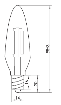 Lamp type: LEDFixing type: E14Voltage: 220~240V ACPower: 2W
TROUBLESHOOTING GUIDE
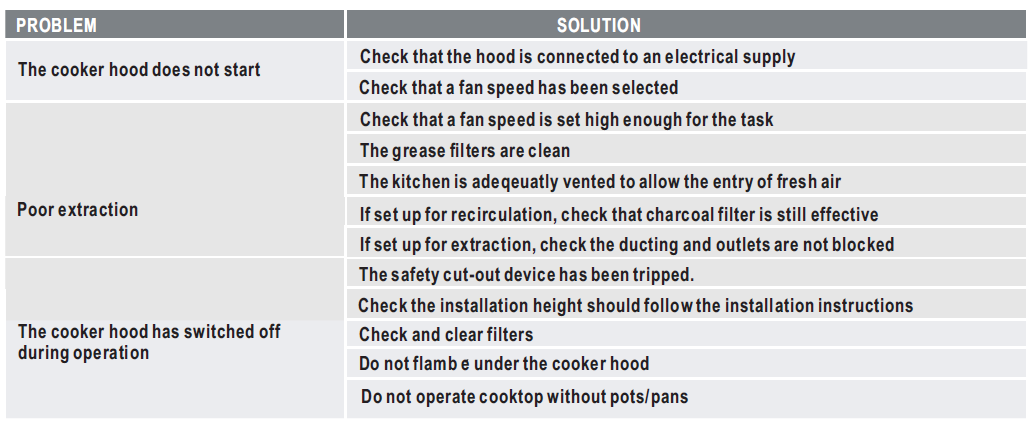
If you have completed all of the above checks and are still experiencing difficulty, please contact your local Electrolux Service Centre.
For more information on all Westinghouse appliances, or for dimension and installation information, call into your retailer, phone or email our customer care team or visit our website:
AUSTRALIAphone: 13 13 49email: web: westinghouse.com.au
NEW ZEALANDphone: 0800 10 66 20email: web: westinghouse.co.nz
WESTINGHOUSE are trademarks of Westinghouse Electric Corporation.Used under license. All Rights Reserved.© 2020 Electrolux Home Products Pty LtdABN 51 004 762 341HYT08VN18041WMAN FAC WRC604WC MAY 20
References
[xyz-ips snippet=”download-snippet”]