
Westinghouse Refrigeration Instruction Manual
REFRIGERATION IK009 INTEGRATION KIT
WTB4600, WTB4604, WTB5400,WTB5404, WBE4500, WBE4502,WBE4504, WBE5300, WBE5304,WFB4204, WRB5004
CONGRATULATIONS
Congratulations and thank you for choosing our integration kit. Before you install the integration kit, we recommend that you read through the entireinstallation manual. To avoid the risks that are always present when you install an electrical appliance, it is important that the integration kit and appliance are installed correctly.Please read the safety instructions in this installation manual as well as the appliance’s user manual to carefully to avoid misuse and hazards. We recommend that you keep this instruction booklet for future reference and pass it on to any future owners. After unpacking the integration kit, please check it is not damaged. If in doubt, do not use the integration kit but contact your local Westinghouse Customer Care Centre
GENERAL WARNINGS
Please read the user manual carefully and store in a handy place for later reference. Pass the user manual on to possible new owners of the appliance.
BEFORE YOU CALL
Please ensure you read the instruction manual fully before you call for service, or a full service fee could be applicable.NOTE: We strongly recommend that a professional builder/cabinet maker builds this unit into required cabinetry prior to finished installation in customer’s kitchen. Westinghouse cannot take responsibility for any installation issues when customer retrofits this product into cabinetry. Cabinet door height built in excess of refrigerator door height will be unsupported and risk bowing.
INFORMATION ON DISPOSAL FOR USERS
 ENVIRONMENT!
 ENVIRONMENT!
- Most of the packaging materials are recyclable. Please dispose of these materials through your local recycling depot or by placing them in appropriate collection containers.
- If you wish to discard this product, please contact your local authorities and ask for the correct method of disposal.
GENERAL WARNINGS
Please read the user manual carefully and store in a handy place for later reference. Pass the user manual on to possible new owners of the appliance.NOTE: We strongly recommend that a professional builder/cabinet maker builds this unit into required cabinetry prior to finished installation in customer’s kitchen. Westinghouse cannot take responsibility for any installation issues when customer retrofits this product into cabinetry. Cabinet door height built in excess of refrigerator door height will be unsupported and risk bowing.NOTE: Please refer to your Appliance User Manual for warnings relating to the appliance
SYMBOLS
 WARNING!This symbol indicates information concerning your personal safety
CAUTION!This symbol indicates information on how to avoid damaging the refrigerator
 IMPORTANT!This symbol indicates tips and information about use of the refrigerator
 ENVIRONMENT!This symbol indicates tips and information about economical and ecological use of the refrigerator
DESCRIPTION
REFRIGERATOR INTEGRATION KIT ITEMS
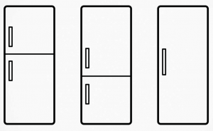
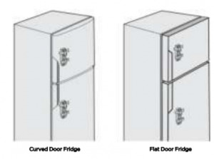
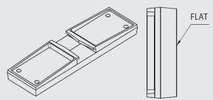
Because this kit is common to a variety of models, you need to select the items required to suit your model. Please be sure to identify the correct slide-housing part (see below), depending on whether your fridge has a curved door or a flat door. The slide-housing part which is not required for your particular model can be discarded. All other parts in this pack are required for installation.
Description |
Item Quantity in kit Quantity required two Model Single do |
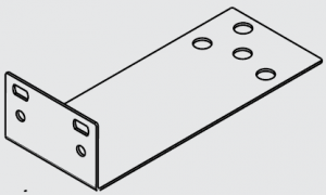 |
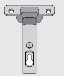
Top hinge bracket 1 1PNº A02986001 |
|
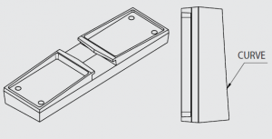
Slide-housing (Curve door) 2 2 1PNº A04098601Slide-housing(Flat door) 2 2 1PNº A04098602 |
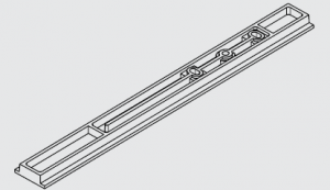 |
Slide-bar 2 2 1PNº A04098501 |
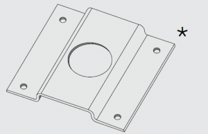 |
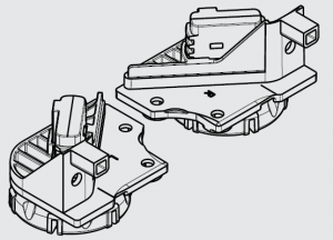
Location bracket front footing 2 2 2PNº A02986101Bottom freezer modelsuse 1 bracket) |
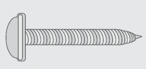 |
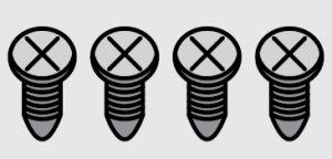
Refrigerator screw s 8 8 4PNº A04120701(741249) |
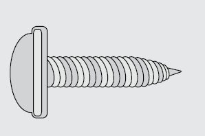 |
Cupboard screws 14 14 11PNº A04120801(1449422) |
 |
120º hinge 5 5 (3+2) 3PNº A04120901(1457832) |
 |
Location bracket front footing 5 5 (3+2) 3PNº A02986101Bottom freezer modelsuse 1 bracket) |
 |
Self tapping wood screws 20 20 12PNº A04121101(1458212) |
 |
Screw Rear Rollers 2 2 2PNº 811949503 |
| Installation Instruction Sheet 1 1 1PNº A04633102 |
DIMENSIONS
CUPBOARD DIMENSIONS IMPORTANT!Pages 4, 5, 6, and 7 should be given to the person responsible for cupboard design and construction.
The cupboard dimensions required for each model are shown on page 5, 6 & 7.
- All sizes are internal and measured in millimetres.
- It is important to ensure that the correct cupboard sizes are used to ensure adequate air flow around the refrigerator.
- Cupboard hinges should be a 120° opening type. (Use hinges supplied).
- Three hinges should be used on each cupboard door higher than 1000mm.
- Ensure the refrigerator is not connected to a power supply whilst installation takes place.
- Each operation should be carried out in the sequence specified in this instruction sheet.
NOTE: All sizes are internal and in millimetres
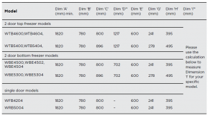
Step 1Measure and confirm Dimension ‘A’.Step 2To calculate Dimension ‘I’ use the equation below.Dim ‘I’ = Dim ‘A’ – (Dim ‘D’ + 5mm) mmStep 3* Add cabinetry thickness to Dimension ‘D’ and Dimension ‘I’ for final measurement before construction.
NOTE: All sizes are internal and measured in millimetres. For ‘lettered’ dimensions refer to the table on page 4.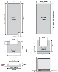
NOTE: The gap is left to ensure the refrigerator door will be allowed to close fully for a good gasket seal.
DIMENSIONS (CONTINUED)
Clearances When installed the refrigerator needs to have adequate air ventilation. It is important to ensure there is good airflow from thefront to underneath and up the rear to the top of the cabinet (see diagrams).
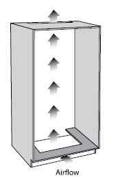
Front airflow cut-out
NOTE: A decorative grill can be fitted so long as it does not obstruct airflow and is removable for cleaning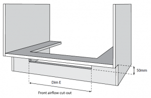 Bottom rear airflow cut-out
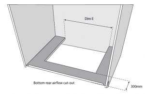 Top rear airflow cut-out
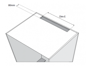
When positioned in a corner the clearance of Dim G onthe hinge side of the cabinet will allow the doors to be opened enough to enable the removal of the crisper bins.
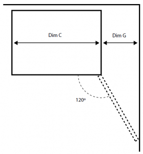
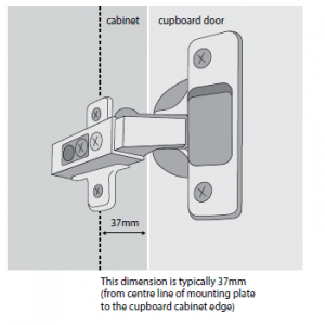
NOTE: Use the 120° hinges supplied with the kit to attach the cupboard door to the cupboard. Attach the hinge to the door to ensure that door can havemaximum opening, i.e. the door edge should not hit the cabinet when the door is fully open.
Cabinet construction
(top mount cupboard shown below)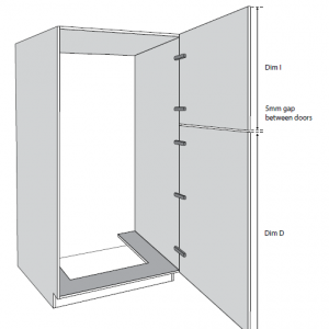
NOTE: If Dim D is larger than 1000mm in height, 3 hinges are required to attach the cupboard door to the cupboard. If Dim D is smaller than 1000mm in height, 2 hinges are required/sufficient.
INSTALLATION
INSTALLATION OF 120˚ HINGE
Please follow the instructions below to install the 120º hinge.
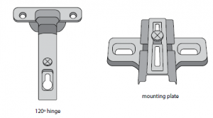
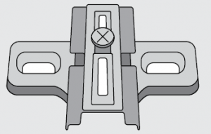
Attach mounting plate with 120º hinge and tighten the screw.
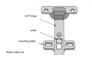
Use self tapping w ood screws P No. A04121101 provided to attach the hinge to the cupboard door

Use screws attached to mounting plate to attach the hinge to the cabinet.
Preparation
- Unpack refrigerator, and remove all packaging.
- Lay the refrigerator down on its back on a piece of soft packing material. Use caution and two people while laying the appliance down.
- Place adjustable rollers in the fully retracted position by screwing height adjusting screw fully anti-clockwise (Figure 2). Do not remove the adjusting nut completely.
- Attach rear rollers. Figure 2
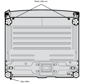 Figure 2
INSTALLATION (CONTINUED)
ATTACHING THE REAR ROLLERS
A set of adjustable back feet/rollers is provided in the kit. These are required to ensure that the product is levelled correctly, failure to fit these may result in the poor operationof door opening.
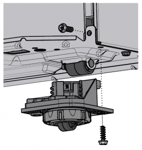
- Temporarily unfasten the screws holding the compressor base plate.
- Fit the assembly with the removed screw and one from the kit (item 11).
- Repeat for the other side.Once fitted turn the adjusting nut on each roller assembly anti-clockwise three full turns, this will raise the cabinet at the rear by approximately 12mm (ensure that the nut iscompletely wound up before turning).Then secure the nut and roller assembly in place with tape (this will prevent the roller assembly from falling out when the refrigerator is place in the cupboard). Stand the refrigerator upright. On a horizontal and flat floor adjust the rollers until the refrigerator is vertical and does not rock.
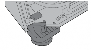 Once fitted turn the adjusting nut on each roller assembly anti-clockwise three full turns, this will raise the cabinet at the rear by approximately 12mm (ensure that the nut iscompletely wound up before turning).
 Then secure the nut and roller assembly in place with tape (this will prevent the roller assembly from falling out when the refrigerator is place in the cupboard). Stand the refrigerator upright. On a horizontal and flat floor adjust the rollers until the refrigerator is vertical and does not rock.
ATTACHING THE TOP HINGE BRACKET
- Remove top hinge cover (Figure 3), cover clips off.
- Remove the three (3) top hinge screws.
- 3Elevate hinge.
- Slide the top hinge bracket into position below the hinge.
- Re-attach hinge and screws ensuring that refrigerator door is still correctly positioned. IMPORTANT!You must ensure that the refrigerator door is:• Parallel with sides and top of cabinet.• The gap between the door and cabinet is typically 10mm allowing the door gasket to act correctly (Figure 4).NOTE: Ensure the gasket acts correctly, i.e. doesn’t make a noise or leave gaps when the door i s closed.
- Recap hinge cover into position.Figure 3Top hinge bracket fitted. Figure 4
 IMPORTANT!You must ensure that the refrigerator door is:• Parallel with sides and top of cabinet.• The gap between the door and cabinet is typically 10mm allowing the door gasket to act correctly (Figure 4).NOTE: Ensure the gasket acts correctly, i.e. doesn’t make a noise or leave gaps when the door i s closed.
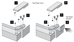 Figure 3Top hinge bracket fitted.
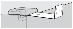
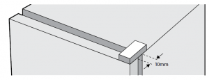 Figure 4
ATTACHING SLIDE-HOUSING TO REFRIGERATOR DOORS
- Ensure slide-housing is positioned squarely as shown.
- Ensure that the slide-housing is positioned on the door as shown in the diagrams.Slide housing (Flat Door version)Slide housing (Curve Door version)NOTE: The slide-housing ‘wider edge’ side must always be closest to the door handle side.INSTALLATION (CONTINUED) 2 door bottom freezer 2 door top freezer single door…and secure with tape. Two door Single doorNOTE: For single door models, the door handle must be completely removed to provide clearance to the cupboard door and the resulting handle mounting holes hidden w itha cover. Installer must use a tape or plastic cover that suits the installation appearance (not supplied).
- While the slide-housing is taped in position, punch a small hole in the refrigerator door skin corresponding to the four (4) holes in the housing (Figure 5).
- The holes should be punched, not drilled, to ensure the maximum thread can be formed in the metal.
- Screw four (4) refrigerator screws into the holes securing the housing in place. The refrigerator screws are supplied in kit (Figure 6).
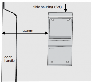 Slide housing (Curve Door version)NOTE: The slide-housing ‘wider edge’ side must always be closest to the door handle side.
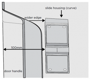 INSTALLATION (CONTINUED)
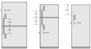 2 door bottom freezer 2 door top freezer single door…and secure with tape.
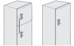 Two door Single doorNOTE: For single door models, the door handle must be completely removed to provide clearance to the cupboard door and the resulting handle mounting holes hidden w itha cover. Installer must use a tape or plastic cover that suits the installation appearance (not supplied).
if you have a two door refrigerator, repeat this process for the other door.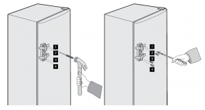 Figure 5 Figure 6
Placing refrigerator in cupboard
- Ensure cupboard is level and square.
- Put refrigerator into cupboard. Use caution and two people if necessary.
- Insert slide bars into slide-housings (Figure 7).
NOTE: Ensure the refrigerator is level in the cupboard. Raise the front of the refrigerator by using the heig ht adjusting screws.
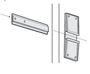 Figure 7
INSTALLATION (CONTINUED)
REFRIGERATOR ALIGNME NT
Position the refrigerator in the cupboard so that:
- Top hinge bracket is against cupboard wall (Figure 8). Front of refrigerator cabinet (with doors open) is parallel to and approximately 100mm from thefront of the cupboard (Figure 9).
- Position bottom location brackets as shown (Figures 9 & 9a). Fit foot in appropriate hole as shown and level refrigerator. (Figure 10).
- NOTE: Do not screw in place yet. For improved aesthetic we suggest painting the brackets to match the colour of the cupboard floor.NOTE: The front adjustable rollers may need raising (rotate anti-clockwise when viewed from above) to achieve this. Figure 8Top Hinge Bracket fitted – note the space between the cupboard and the side of the refrigerator is to be approximately 85mm. Figure 9Figure 9a – Hinge sideFigure 10
- Slowly close the cupboard door (pushing the refrigerator back) until it is slightly ajar, i.e. with a gap of about 4mm (Figure 11).You may have to reposition the refrigerator back or forward until the 4mm gap is obtained. Ensure that the refrigerator remains parallel as you do this. Once you have the correct gap, proceed to the next step . Figure 11
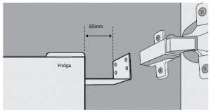 Figure 8Top Hinge Bracket fitted – note the space between the cupboard and the side of the refrigerator is to be approximately 85mm.
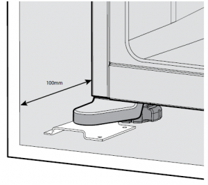 Figure 9
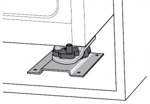 Figure 9a – Hinge side
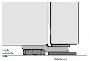 Figure 10
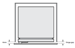 Figure 11
NOTE: The gap is left to ensure the refrigerator door will be allowed to close fully for a good gasket seal.
SECURING THE REFRIGERATOR IN THE CUPBOARD
NOTE: When attaching all screws to cupboard, first drill a 2mm pilot hole in the correct position. This will allo w easy hand insertion of self tapping screw.
- Screw in top hinge bracket to the cupboard wall using 4 cupboard screws provided. This will secure the top of the refrigerator (Figure 12).
- Screw down both foot brackets to cupboard floor with 2 cupboard screws. This will secure the bottom of the refrigerator (Figure 13.) Figure 12 Figure 13
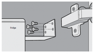 Figure 12
 Figure 13
ATTACHING SLIDE-BAR TO THE CUPBOARD DOOR
- Fully open cupboard door (120°). Open refrigerator door until it rests against the cupboard door.
- Position slide-bar in slide-housing so that all three holes are visible when both doors are fully open (120°). This position is typically 230mm from the edge of the slide housing (Figure 14).
- Position slide-bar in slide-housing so that all three holes are visible when both doors are fully open (120°). This position is typically 230mm from the edge of the slide housing (Figure 14).Figure 14Whilst slide-bar is still in housing
- Rotate slide-bar to uppermost alignment, mark a line on cupboard door (Figure 15). Figure 15INSTALLATION (CONTINUED)
- Rotate slide-bar to lower alignment, mark a line on cupboard door (Figure 16). Figure 16Figure 16
- Remove slide-bar and draw line to indicate central alignment (Figure 17). Figure 17
- Replace slide-bar and align to centre line marked in previous operation (Figure 18).Figure 18
- Secure slide-bar by driving a cupboard screw into the centre of the inner slot Fig 19. Gently test closing the door. Figure 19
- If the action is smooth and the slider does not move in relation to the cupboard door, drive another cupboard screw into the end slot Fig 20. Figure 20
- Open and close the door a number of times. If the action is not smooth, loosen the screws and re-adjust the slide bar. Once the desired smooth action isachieved attach the central locking screw Fig 21. Figure 20
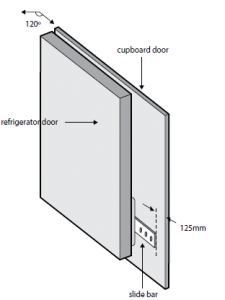 Figure 14Whilst slide-bar is still in housing
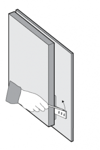 Figure 15INSTALLATION (CONTINUED)
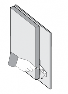 Figure 16
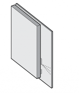 Figure 17
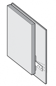 Figure 18
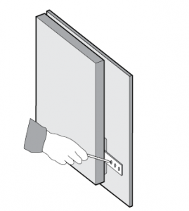 Figure 19
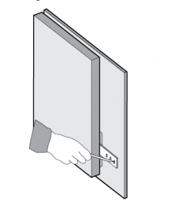 Figure 20
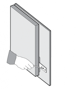 Figure 20
Repeat this procedure for the second slide bar if necessary.This completes the installation procedure.Customers please note.In the unlikely event service is required on an integrated refrigerator during the warranty period it is the customer’s responsibility to remove the refrigerator from the cupboard.Removal of the refrigerator from the cupboard is not covered by warranty. For full details of the warranty terms and conditions please refer to the information contains withyour appliances.
For more information on all Westinghouse appliances, or for dimension and installation information, call into your retailer, phone or email our customer care team or visit our website:
AUSTRALIAElectrolux Home Products AustraliaPhone: 13 13 49Email: Website: westinghouse.com.au
NEW ZEALANDElectrolux (NZ) LimitedPhone: 0800 436 234Email: Website: westinghouse.co.nz
Read More About This Manual & Download PDF:
References
[xyz-ips snippet=”download-snippet”]