
DRYER SAFETY
Your safety and the safety of others are very important.
We have provided many important safety messages in this manual and on your appliance. Always read and obey all safety messages.
 This is the safety alert symbol. This symbol alerts you to potential hazards that can kill or hurt you and others. All safety messages will follow the safety alert symbol and either the word “DANGER” or “WARNING.” These words mean:
![]() A DANGER You can be killed or seriously injured if you don’t immediate! follow instructions.
A DANGER You can be killed or seriously injured if you don’t immediate! follow instructions.
![]() A DANGER You can be killed or seriously injured if you don’t follow instructions.
A DANGER You can be killed or seriously injured if you don’t follow instructions.
All safety messages will tell you what the potential hazard is, tell you how to reduce the chance of injury, and tell you what can happen if the instructions are not followed.
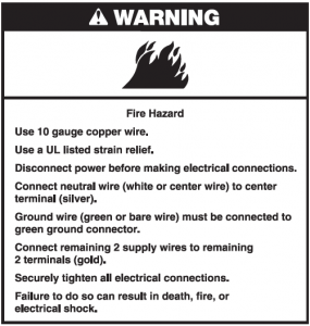
 WARNING – “Risk of Fire”
– Clothes dryer installation must be performed by a qualified installer. – Install the clothes dryer according to the manufacturer’s instructions and local codes. – Do not install a clothes dryer with flexible plastic venting materials or flexible metal (foil type) duct. If flexible metal duct is installed, it must be of a specific type identified by the appliance manufacturer as suitable for use with clothes dryers. Flexible venting materials are known to collapse, be easily crushed, and trap lint. These conditions will obstruct clothes dryer airflow and increase the risk of fire. – To reduce the risk of severe injury or death, follow all installation instructions.– Save these instructions.
State of California Proposition 65 Warnings: WARNING: This product contains one or more chemicals known to the State of California to cause cancer. WARNING: This product contains one or more chemicals known to the State of California to cause birth defects or other reproductive harm.
IMPORTANT SAFETY INSTRUCTIONS
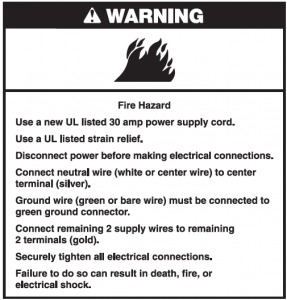
WARNING: To reduce the risk of fire, electric shock, or injury to persons when using the dryer, follow basic precautions, including the following:
- Read all instructions before using the dryer.
- Do not place items exposed to cooking oils in your dryer. Items contaminated with cooking oils may contribute to a chemical reaction that could cause a load to catch fire.
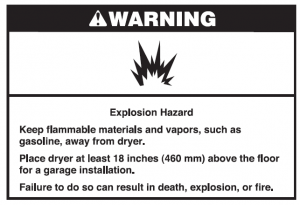
- Do not dry articles that have been previously cleaned in, washed in, soaked in, or spotted with gasoline, dry-cleaning solvents, or other flammable or explosive substances as they give off vapors that could ignite or explode.
- Do not allow children to play on or in the dryer. Close supervision of children is necessary when the dryer is used near children.
- Before the dryer is removed from service or discarded, remove the door to the drying compartment.
- Do not reach into the dryer if the drum is moving.
- Do not install or store the dryer where it will be exposed to the weather.
- Do not tamper with controls.
- Do not repair or replace any part of the dryer or attempt any servicing unless specifically recommended in this Use and Care Guide or in published user-repair instructions that you understand and have the skills to carry out.
- Do not use fabric softeners or products to eliminate static unless recommended by the manufacturer of the fabric softener or product.
- Do not use heat to dry articles containing foam rubber or similarly textured rubber-like materials.
- Clean lint screen before or after each load.
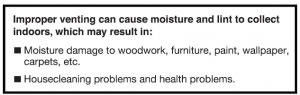
- Keep area around the exhaust opening and adjacent surrounding areas free from the accumulation of lint, dust, and dirt.
- The interior of the dryer and exhaust vent should be cleaned periodically by qualified service personnel.
- See “Electrical Requirements” located in the installation instructions for grounding instructions.SAVE THESE INSTRUCTIONS
IMPORTANT SAFETY INSTRUCTIONSWhen discarding or storing your old clothes dryer, remove the door.SAVE THESE INSTRUCTIONS
INSTALLATION REQUIREMENTS
Tools and PartsGather the required tools and parts before starting installation. Read and follow the instructions provided with any tools listed here.
Tools needed:

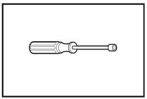
Flat-blade screwdriver
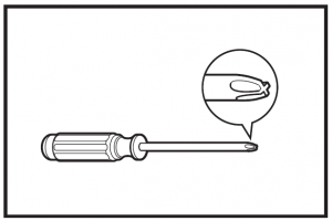
#2 Phillips screwdriverWire stripper(direct wire installations)
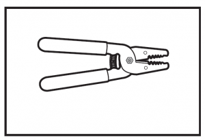
Wire stripper(direct wire installations)
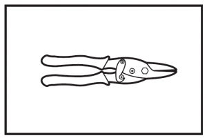
Tin snips(new vent installations)
1/4″ nut driver (recommended)

Vent clamps

Adjustable wrench that opens to 1″ (25 mm) or hex-head socket wrench

Utility knife
Tape measure
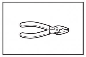
Pliers

Level
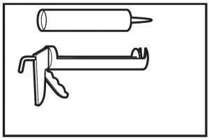
Caulking gun and compound (for installing new exhaust vent)
Parts supplied (all models):

Leveling legs (4)
Parts package is located in dryer drum. Check that all partsare included.Parts needed:Check local codes. Check existing electrical supply and venting, and read “Electrical Requirements” and “Venting Requirements” before purchasing parts.Mobile home installations require metal exhaust system hardware, available for purchase from the dealer from whom you purchased your dryer. For further information, please reference the “Assistance or Service” section of the “Use and Care Guide”.If using a power supply cord:Use a UL listed power supply cord kit marked for use with clothes dryers. The kit should contain:
- A UL listed 30-amp power supply cord, rated 120/240 volt minimum. The cord should be type SRD or SRDT and beat least 4 ft. (1.22 m) long. The wires that connect to thedryer must end in ring terminals or spade terminals with upturned ends.
- A UL listed strain relief.
Location Requirements
You will need:
- A location allowing for proper exhaust installation.See “Venting Requirements.”
- A separate 30 amp circuit.
- If you are using power supply cord, a grounded electrical outlet located within 2 ft. (610 mm) of either side of dryer.See “Electrical Requirements.”
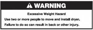
- A sturdy floor to support the total weight (dryer and load) of 200 lbs. (90.7 kg). The combined weight of a companion appliance should also be considered.
- Level floor with maximum slope of 1″ (25 mm) under entire dryer. (If slope is greater than 1″ [25 mm], install ExtendedDryer Feet Kit, Part Number 279810.) If not level, clothesmay not tumble properly and automatic sensor cycles maynot operate correctly.Do not operate your dryer at temperatures below 45°F (7°C). At lower temperatures, the dryer might not shut off at the end of an automatic cycle. Drying times can be extended.The dryer must not be installed or stored in an area where it will be exposed to water and/or weather.Check code requirements. Some codes limit, or do not permit, installation of the dryer in garages, closets, mobile homes, or sleeping quarters. Contact your local building inspector.Installation clearances:The location must be large enough to allow the dryer door to open fully.Dryer Dimensions
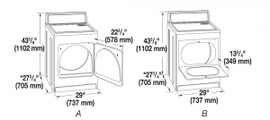
A. Wide opening side-swing doorB. Wide opening hamper door*Most installations require a minimum 5½” (140 mm) clearancebehind the dryer for the exhaust vent with elbow. See “VentingRequirements.”
Minimum spacing for recessed area or closet installationThe dimensions shown following are for the minimum spacing allowed.
- Additional spacing should be considered for ease of installation and servicing.
- Additional clearances might be required for wall, door, and floor moldings.
- Additional spacing of 1″ (25 mm) on all sides of the dryeris recommended to reduce noise transfer.
- For closet installation, with a door, minimum ventilation openings in the top and bottom of the door are required.Louvered doors with equivalent ventilation openingsare acceptable.
- Companion appliance spacing should also be considered.
Minimum Required Spacing
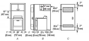
A. Recessed areaB. Side view – closet or confined areaC. Closet door with vents*Additional spacing recommended
Mobile home – Additional installation requirementsThis dryer is suitable for mobile home installations. The installation must conform to the Manufactured Home Construction and Safety Standard, Title 24 CFR, Part 3280 (formerly the Federal Standard for Mobile Home Constructionand Safety, Title 24, HUD Part 280).
- Metal exhaust system hardware, which is available for purchase from your dealer.
- Special provisions must be made in mobile homes to introduce outside air into the dryer. The opening (suchas a nearby window) should be at least twice as largeas the dryer exhaust opening.
Electrical Requirements
It is your responsibility:
- To contact a qualified electrical installer.
- To be sure that the electrical connection is adequate and in conformance with the National Electrical Code, ANSI/NFPA 70-latest edition and all local codes and ordinances.The National Electrical Code requires a 4-wire power supply connection for homes built after 1996, dryer circuits involved in remodeling after 1996, and all mobile home installations.A copy of the above code standards can be obtained from: National Fire Protection Association, One Batterymarch Park, Quincy, MA 02269.
- To supply the required 3 or 4 wire, single phase, 120/240 volt, 60 Hz, AC only electrical supply (or 3 or 4 wire, 120/208 volt electrical supply, if specified on the serial/rating plate) on a separate 30-amp circuit, fused on both sides of the line. A time-delay fuse or circuit breaker is recommended. Connect to an individual branch circuit. Do not have a fuse in the neutral or grounding circuit.
- Do not use an extension cord.
- If codes permit and a separate ground wire is used, it is recommended that a qualified electrician determine that the ground path is adequate.Electrical ConnectionTo properly install your dryer, you must determine the type of electrical connection you will be using and follow the instructions provided for it here.
- If local codes do not permit the connection of a neutral ground wire to the neutral wire, see “Optional 3-wire connection” section.
- This dryer is manufactured ready to install with a 3-wire electrical supply connection. The neutral ground wire is permanently connected to the neutral conductor (white wire) within the dryer. If the dryer is installed with a 4-wire electrical supply connection, the neutral ground wire must be removed from the external ground connector screw (green screw), and secured under the neutral terminal (center or white wire) of the terminal block. When the neutral ground wire is secured under the neutral terminal (center or white wire) of the terminal block, the dryer cabinet is isolated from the neutral conductor.
- A 4-wire power supply connection must be used when the dryer is installed in a location where grounding through the neutral conductor is prohibited. Grounding through the neutral is prohibited for (1) new branch-circuit installations, (2) mobile homes, (3) recreational vehicles, and (4) areas where local codes prohibit grounding through the neutral conductors.If using a power supply cord:Use a UL listed power supply cord kit marked for use withclothes dryers. The kit should contain:
- A UL listed 30-amp power supply cord, rated 120/240 volt minimum. The cord should be type SRD or SRDT and beat least 4 ft. (1.22 m) long. The wires that connect to thedryer must end in ring terminals or spade terminals with upturned ends.
- A UL listed strain relief.
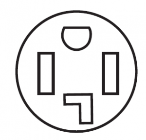
If your outlet looks like this:
 Then choose a 4-wire power supply cord with ring or spade terminals and UL listed strain relief. The 4-wire power supply cord, at least4 ft. (1.22 m) long, must have 4 10-gauge solid copper wires and match a 4-wire 4-wire receptacle(14-30R) receptacle of NEMA Type 14-30 R. The ground wire (ground conductor) may be either green or bare. The neutral conductor must be identified by a white cover.
If your outlet looks like this:
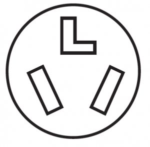 Then choose a 3-wire power supply cord with ring or spade terminals and UL listed strain relief. The 3-wire power supply cord, at least4 ft. (1.22 m) long, must have 3 10-gauge solid copper wires and match a 3-wire 3-wire receptacle receptacle of NEMA Type 10-30R.(10-30R)
If connecting by direct wire:Power supply cable must match power supply (4-wire or 3-wire) and be:
- Flexible armored cable or nonmetallic sheathed copper cable (with ground wire), covered with flexible metallic conduit. All current-carrying wires must be insulated.
- 10-gauge solid copper wire (do not use aluminum).
- At least 5 ft. (1.52 m) long.
GROUNDING INSTRUCTIONS
For a grounded, cord-connected dryer: This dryer must be grounded. In the event of malfunction or breakdown, grounding will reduce the risk of electric shock by providing a path of least resistance for electric current. This dryer uses a cord having an equipment-grounding conductor and a grounding plug. The plug must be plugged into an appropriate outlet that is properly installed and grounded in accordance with all local codes and ordinances.
For a permanently connected dryer: This dryer must be connected to a grounded metal, permanent wiring system, or an equipment-grounding conductor must be run with the circuit conductors and connected to the equipment-grounding terminal or lead on the dryer. WARNING: Improper connection of the equipment-grounding conductor can result in a risk of electric shock. Check with a qualified electrician or service representative or personnel if you are in doubt as to whether the dryer is properly grounded. Do not modify the plug on the power supply cord: if it will not fit the outlet, have a proper outlet installed by a qualified electrician.
SAVE THESE INSTRUCTIONS
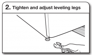
Install Leveling Legs
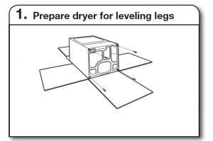
To avoid damaging floor, use a large flat piece of cardboardfrom dryer carton; place under entire back edge of dryer.Firmly grasp dryer body (not console panel) and gently laydryer down on cardboard.

Examine leveling legs, find diamond marking. Screw legs intoleg holes by hand, use a wrench to finish turning legs untildiamond marking is no longer visible.Now stand the dryer on its feet. Slide the dryer until it isclose to its final location. Leave enough room for electricalconnection and to connect the exhaust vent.
Electrical Connection
Power Supply Cord
Electrical Connection Options
1. Choose electrical connection type
 Power supply cord 4-wire receptacle(NEMA Type 14-30R): Go to steps 1-2 onpage 9 for power supply cord strain relief:then steps 3-6 for 4-wire Power SupplyCord Connection section. Then, go toVenting Requirements.
 Power supply cord 3-wire receptacle(NEMA Type 10-30R): Go to steps 1-2 onpage 9 for power supply cord strain relief:then steps 3-5 for 3-wire Power SupplyCord Connection section.Then go to Venting Requirements.
 4-wire direct connection: Go to steps1-2 on page 10 for direct wire strain relief:then steps 3-8 for 4-wire Direct WireConnection section. Then go to VentingRequirements.
![]() 3-wire direct connection: Go to steps1-2 on page 11 for direct wire strain relief:then steps 3-7 for 3-wire Direct WireConnection section. Then go to VentingRequirements.
3-wire direct connection: Go to steps1-2 on page 11 for direct wire strain relief:then steps 3-7 for 3-wire Direct WireConnection section. Then go to VentingRequirements.
NOTE: If local codes do not permit connection of acabinet-ground conductor to neutral wire, go to “Optional3-wire Connection” section. This connection may beused with either a power supply cord or a direct wireconnection.
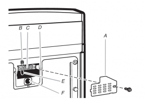
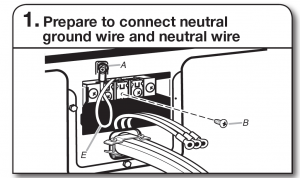
Before you start, disconnect power. Remove hold-down screw(D) and terminal block cover (A).A. Terminal block coverB. External ground conductor screwC. Center terminal block screwD. Hold-down screwE. Neutral ground wireF. Hole below terminal block cover
Power Supply Cord Connection
Power supply cord strain relief
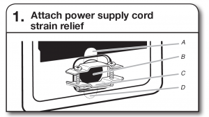
Remove the screws from a 3/4″ (19 mm) UL listed strain relief(UL marking on strain relief). Put the tabs of the two clampsections (C) into the hole (B) below the terminal block openingso that one tab is pointing up (A) and the other is pointingdown (D), and hold in place. Tighten strain relief screws justenough to hold the two clamp sections (C) together.
Put power supply cord through the strain relief. Be sure thatthe wire insulation on the power supply cord is inside thestrain relief. The strain relief should have a tight fit with thedryer cabinet and be in a horizontal position. Do not furthertighten strain relief screws at this point.For 3-wire Power Supply Cord Connection, see page 9.For 4 wire Power Supply Cord Connection, continue tostep 3.
4-wire Power Supply Cord Connection
IMPORTANT: A 4-wire connection is required for mobilehomes and where local codes do not permit the use of 3-wireconnections.
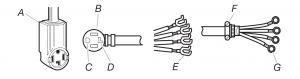
A. 4-wire receptacle (NEMA type 14-30R)B. 4-prong plugC. Ground prongD. Neutral prongE. Spade terminals with upturned endsF. 3/4″ (19 mm) UL listed strain reliefG. Ring terminals
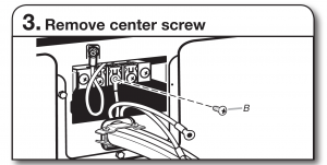
Remove center terminal block screw (B). Remove neutralground wire (E) from external ground conductor screw (A).
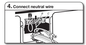
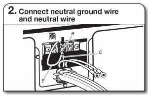
Connect neutral ground wire (E) and neutral wire (white orcenter) (C) of power supply cord under center terminal blockscrew (B). Tighten screw.

Connect ground wire (F) (green or bare) of power supply cordto external ground conductor screw (A). Tighten screw.
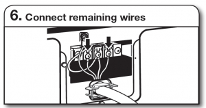
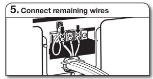
Connect remaining wires to outer terminal block screws.Tighten screws. Finally, reinsert tab of terminal block coverinto slot of dryer rear panel. Secure cover with hold-downscrew. Now, go to Venting Requirements.
3-wire Power Supply Cord ConnectionUse where local codes permit connecting cabinet-groundconductor to neutral wire.
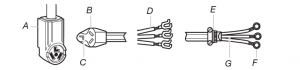
A. 3-wire receptacle (NEMA type 10-30R)B. 3-wire plugC. Neutral prongD. Spade terminals with upturned endsE. 3/4″ (19 mm) UL listed strain reliefF. Ring terminalsG. Neutral (white or center wire)

Remove center terminal block screw (B).

Connect neutral wire (white or center) (C) of power supply cordto center terminal block screw (B). Tighten screw.
Connect remaining wires to outer terminal block screws.Tighten screws. Finally, reinsert tab of terminal block cover intoslot of dryer rear panel. Secure cover with hold-down screw.Now, go to Venting Requirements.
Direct Wire Connection
Direct wire strain relief

Unscrew the removable conduit connector (A) and any screwsfrom a 3/4″ (19 mm) UL listed strain relief (UL marking on strainrelief). Put the threaded section of the strain relief through thehole (B) below the terminal block opening. Reaching inside theterminal block opening, screw the removable conduit connectoronto the strain relief threads (C).

Put direct wire cable through the strain relief. The strain reliefshould have a tight fit with the dryer cabinet and be in ahorizontal position. Tighten strain relief screws.For 3-wire Direct Wire Connection, see page 11.For 4 wire Direct Wire Connection, continue to step 3 below.
4-wire Direct Wire ConnectionIMPORTANT: A 4-wire connection is required for mobile homesand where local codes do not permit 3-wire connections.

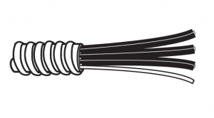
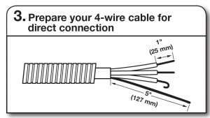
Direct wire cable must have 5 ft. (1.52 m) of extra length so dryermay be moved if needed.Strip 5″ (127 mm) of outer covering from end of cable, leavingbare ground wire at 5″ (127 mm). Cut 11/2″ (38 mm) fromremaining 3 wires. Strip insulation back 1″ (25 mm). Shape endsof wires into hooks.
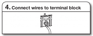
To connect wires to terminal block, place hooked end of wireunder terminal block screw, facing to the right, squeeze hookedend together and tighten screw.
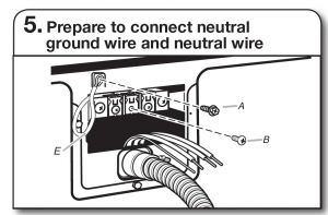
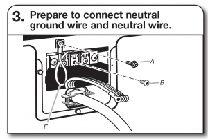
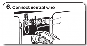
Remove center terminal block screw (B). Remove neutralground wire (E) from external ground conductor screw (A).

Connect neutral ground wire (E) and place hooked end (hookfacing right) of neutral wire (white or center wire) (C) of directwire cable under center screw of terminal block (B). Squeezehooked ends together and tighten screw.

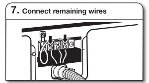
Connect ground wire (green or bare) (F) of direct wire cableto external ground conductor screw (A). Tighten screw.
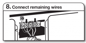
Place hooked ends of remaining direct wire cable wires underouter terminal block screws (hooks facing right). Squeeze hookedends together and tighten screws. Finally, reinsert tab of terminalblock cover into slot of dryer rear panel. Secure cover with holddownscrew. Now, go to Venting Requirements.
3-wire Direct Wire ConnectionUse where local codes permit connecting cabinet-groundconductor to neutral wire.
Direct wire cable must have 5 ft. (1.52 m) of extra length sodryer may be moved if needed.Strip 31/2″ (89 mm) of outer covering from end of cable. Stripinsulation back 1″ (25 mm). If using 3-wire cable with groundwire, cut bare wire even with outer covering. Shape wire endsinto hooks.

To connect wires to terminal block, place hooked end of wireunder terminal block screw, facing to the right, squeeze hookedend together and tighten screw.

Remove center terminal block screw (B).
Place hooked end of neutral wire (white or center) (C) of directwire cable under center terminal block screw (B). Squeezehooked end together. Tighten screw.
Place hooked ends of remaining direct wire cable wires underouter terminal block screws (hooks facing right). Squeeze hookedends together and tighten screws. Finally, reinsert tab of terminalblock cover into slot of dryer rear panel. Secure cover with holddownscrew. Now, go to Venting Requirements.
Optional 3-wire ConnectionYou must verify with a qualified electrician that thisgrounding method is acceptable before connecting.
Remove center terminal block screw (B). Remove neutral groundwire (E) from external ground conductor screw (A).
Connect neutral ground wire (E) and neutral wire (white orcenter wire) (C) of power supply cord or cable under centerterminal block screw (B). Tighten screw.

Place hooked ends of remaining wires under outer terminalblock screws (hooks facing right). Tighten screws.
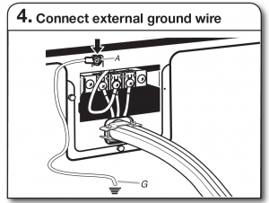
Connect a separate copper ground wire (G) from the externalground conductor screw (A) to an adequate ground. Finally,reinsert tab of terminal block cover into slot of dryer rearpanel. Secure cover with hold-down screw. Now, go to VentingRequirements.
VENTING
Venting Requirements
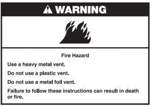
WARNING: To reduce the risk of fire, this dryer MUST BE EXHAUSTED OUTDOORS.IMPORTANT: Observe all governing codes and ordinances.Dryer exhaust must not be connected into any gas vent, chimney, wall, ceiling, attic, crawlspace, or a concealed space of a building. Only rigid or flexible metal vent shall be used for exhausting.
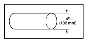
4″ (102 mm) heavy metal exhaust vent
- Only a 4″ (102 mm) heavy metal exhaust vent and clamps may be used.
- Do not use plastic or metal foil vent.Rigid metal vent:
- Recommended for best drying performance and to avoid crushing and kinking.Flexible metal vent: (Acceptable only if accessible to clean)
- Must be fully extended and supported in final dryer location.
- Remove excess to avoid sagging and kinking that may result in reduced airflow and poor performance.
- Do not install in enclosed walls, ceilings, or floors.
- The total length should not exceed 73/4 ft. (2.4 m).
NOTE: If using an existing vent system, clean lint from entire length of the system and make sure exhaust hood is not plugged with lint. Replace plastic or metal foil vents with rigid metal or flexible metal vents. Review “Vent System Chart” and, if necessary, modify existing vent system to achieve best drying performance.
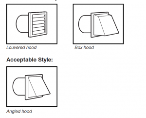
Exhaust hoods:
- Must be at least 12″ (305 mm) from ground or any object that may obstruct exhaust (such as flowers, rocks, bushes, or snow).
Recommended Styles:
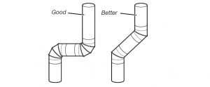
Elbows:
- 45° elbows provide better airflow than 90° elbows.
Clamps:
- Use clamps to seal all joints.
- Exhaust vent must not be connected or secured with screws or other fastening devices that extend into interior of ductand catch lint. Do not use duct tape.
See “Venting Kits” for more information.
Plan Vent SystemRecommended exhaust installationsTypical installations vent the dryer from the rear of the dryer. Other installations are possible.
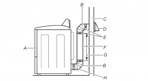
A. Dryer E. ClampsB. Elbow F. Rigid metal or flexible metal ventC. Wall G. Vent length necessary to connect elbowsD. Exhaust hood H. Exhaust outlet

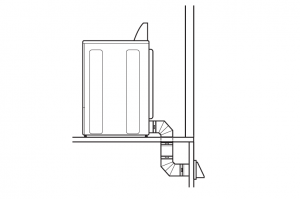
 Alternate installations for close clearancesVenting systems come in many varieties. Select the type bestfor your installation. Two close-clearance installations are shown. Refer to the manufacturer’s instructions.
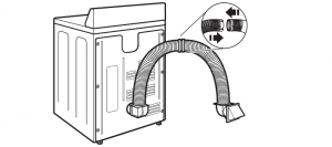
Over-The-Top installation (also available with one offset elbow)

Periscope installation
NOTE: The following kits for close clearance alternate installations are available for purchase.
Venting KitsFor more information, call 1-800-901-2042, or visit us atwww.applianceaccessories.com. In Canada, call1-800-807-6777 or visit us at www.whirlpoolparts.ca.
Part Number Descriptions8171587RP 0–5″ Metal vent periscope4396037RP 0″-18″ Metal vent periscope4396011RP 18″ – 29″ Metal vent periscope4396014 29″ – 50″ Metal vent periscope4392892 In-Wall metal DuraVent™ Periscope4396028 Sure Connect™ venting kit (over-the-top installation)4396009RP 5′ Universal connect vent, flexible dryer venting4396010RP 6′ SecureConnect™ vent, flexible dryer venting4396013RB Dryer vent installer’s kit4396033RP 5′ flexible dryer venting with clamps4396727RP 8′ flexible dryer venting with clamps4396004 Dryer offset elbow4396005 Wall offset elbow4396006RW DuraSafe™ close elbow4396007RW Through-the-wall vent cap4396008RP 4″ steel dryer venting clamps – 2 pack8212662 Flush mounting louvered vent hood 4″
Special provisions for mobile home installations:The exhaust vent must be securely fastened to a noncombustibleportion of the mobile home structure and must not terminatebeneath the mobile home. Terminate the exhaust vent outside.
Determine vent path:
- Select route that will provide straightest and most directpath outdoors.
- Plan installation to use fewest number of elbows and turns.
- When using elbows or making turns, allow as much roomas possible.
- Bend vent gradually to avoid kinking.
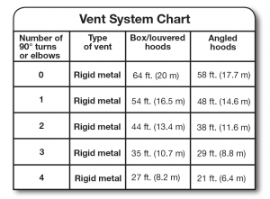
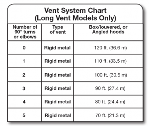
- Use as few 90° turns as possible.Determine vent length and elbows needed for bestdrying performance:
- Use following Vent system chart to determine type of ventmaterial and hood combinations acceptable to use.NOTE: Do not use vent runs longer than those specifiedin Vent system chart. Exhaust systems longer than thosespecified will:
- Shorten life of dryer.
- Reduce performance, resulting in longer drying timesand increased energy usage.
The Vent system chart provides venting requirements that willhelp achieve best drying performance.
Install Vent System

Install exhaust hood and use caulking compound to sealexterior wall opening around exhaust hood.
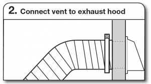
Vent must fit over the exhaust hood. Secure vent to exhausthood with 4″ (102 mm) clamp. Run vent to dryer locationusing straightest path possible. Avoid 90° turns. Use clampsto seal all joints. Do not use duct tape, screws, or otherfastening devices that extend into interior of vent to securevent, because they can catch lint.
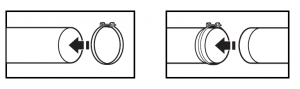
Connect Vent
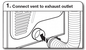
Using a 4″ (102 mm) clamp, connect vent to exhaust outletin dryer. If connecting to existing vent, make sure vent isclean. Dryer vent must fit over dryer exhaust outlet and insideexhaust hood. Check that vent is secured to exhaust hoodwith a 4″ (102 mm) clamp.

Move dryer to final location. Avoid crushing or kinking vent.After dryer is in place, remove corner posts and cardboardfrom under the dryer.
Level Dryer
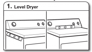
Check levelness of dryer from side to side. Repeat fromfront to back.
NOTE: The dryer must be level for the moisture sensing systemto operate correctly.
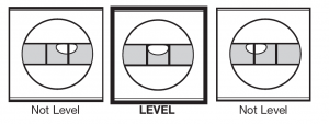
If dryer is not level, prop up using a wood block, use wrenchto adjust legs up or down, and check again for levelness.Once legs are level, make sure all four legs are snug againstthe ground before tightening them.
Complete Installation Checklist
- Check that all parts are now installed. If there is an extra
- part, go back through steps to see what was skipped.
- Check that you have all of your tools.
- Dispose of/recycle all packaging materials.
- Check dryer’s final location. Be sure vent is not crushedor kinked.
- For power supply cord installation, plug into an outlet.For direct wire installation, turn on power.
- Check that dryer is level. See “Level Dryer”.
- Remove film on console and any tape remaining on dryer.
- Wipe dryer drum interior thoroughly with a damp cloth toremove any dust.
- Read “Dryer Use” in your “Use and Care Guide”.
- Set the dryer on a full heat cycle (not an air cycle) for
- minutes and start the dryer.If the dryer will not start, check the following:■ Controls are set in a running or “On” position.■ Start button has been pushed firmly.■ Dryer is plugged into an outlet and/or electrical supplyis on.■ Household fuse is intact and tight, or circuit breaker hasnot tripped.■ Dryer door is closed.
- When the dryer has been running for 5 minutes, open thedryer door and feel for heat. If you feel heat, cancel cycle andclose the door.If you do not feel heat, turn off dryer, and check thefollowing:■ There may be 2 household fuses or circuit breakers forthe dryer. Check that both fuses are intact and tight, orthat both circuit breakers have not tripped. If there is stillno heat, contact a qualified technician.
NOTE: You may notice an odor when the dryer is first heated.This odor is common when the heating element is first used.The odor will go away.
Reverse Door Swing (Optional)
29″ Super Wide Side-Swing Door

Place towel on top of dryer to avoid damaging the surface.NOTE: Magnetized screw driver is helpful.
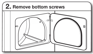
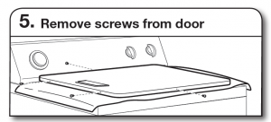
Open dryer door. Remove bottom screws from dryer cabinetside of hinges. Loosen (do not remove) top screws from dryercabinet side of hinges.

Lift door until top screws in dryer cabinet are in large part ofhinge slot. Pull door forward off screws. Set door (handle sideup) on top of dryer. Remove top screws from dryer cabinet.

Remove screws attaching hinges to door.
Remove screws at top, bottom, and side of door (4 screws)that hold the inner and outer door together. Holding door overtowel on dryer, grasp sides of outer door and lift to separate itfrom inner door. Set outer door aside.NOTE: Do not pry apart with putty knife or screwdriver.Do not pull on door seal or plastic door catches.
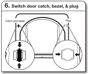
Remove the door catch, bezel, and plug from the inside ofthe inner door by squeezing and pulling/pushing them. Placethe door catch, bezel, and plug on the sides opposite fromwhere they were.
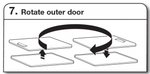
Rotate outer door 180º and set it back down on inner door.Reattach outer door panel to inner door panel so handle ison the side where hinges were just removed. Insert 4 doorscrews.
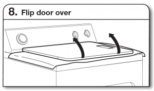
Flip door over so handle side is down.

Reattach door hinges to dryer door so that the larger hole isat the bottom of the hinge.
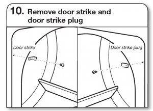
Remove door strike and door strike plug from dryer cabinet.Insert the door strike into door strike plug hole and securewith screw. Insert door strike plug into original door strikehole and secure with screw.
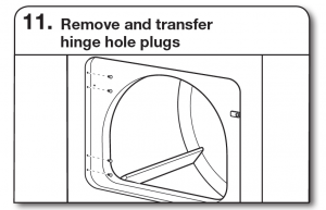
Use a small, flat-blade screwdriver to gently remove 4 hingehole plugs on left side of dryer cabinet. Transfer plugs intohinge holes on opposite side of dryer cabinet.
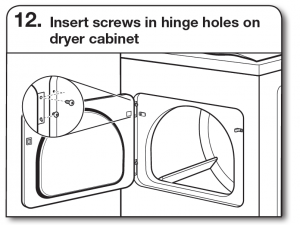
NOTE: Two people may be needed to reinstall door.Insert screws into the bottom holes on left side of dryercabinet. Tighten screws halfway. Position door so largeend of door hinge slot is over screws. Slide door up soscrews are in bottom of slots. Tighten screws. Insert andtighten top screws in hinges.
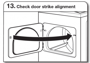
Close door and check that door strike aligns with doorcatch. If it is needed, slide door catch left or right within slotto adjust alignment.
TroubleshootingSee the Use and Care Guide or visit our website and referenceFrequently Asked Questions to possibly avoid the cost of aservice call.
Read More About This Manual & Download PDF:
Electric Dryer W10514172A/W10514174A-SP Installation Manual – Electric Dryer W10514172A/W10514174A-SP Installation Manual –