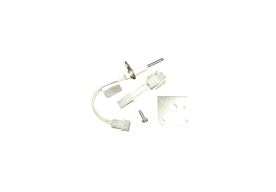
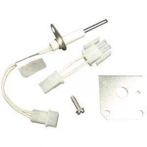
WHITE-RODGERS Mini Ignitor Conversion Kit
PRECAUTIONS
|
|
||
 |
 |
 |
Failure to comply with the following warnings could result in personal injury or property damage. FIRE HAZARD
SHOCK HAZARD
EXPLOSION HAZARD
|
 |
Installation should be done by a qualified heating and air conditioning contractor or licensed electrician. Do not exceed the specifications ratings. All wiring must conform to local and national electrical codes and ordinances. Following installation or replacement, follow manufacturer’s recommended installation/service instructions to ensure proper operation. |
INSTALLATION
Hot surface ignitors get hot, up to 2500°F! Therefore, wait several minutes allowing the ignitor to cool down, before attempting any service work. Failure to do so will cause severe personal injury. Failure to turn off all gas and electrical power can cause severe injury, death or property damage. |
Fragile: Care should be exercised in handling the ignitor to avoid breakage. Do not touch ignitor surface with hands. |
Removal Procedures
- Disconnect the electrical power supplied to the furnace and verify power is off with a volt meter before servicing.
- Close manual gas service valve to furnace.
- Remove the top burner compartment door from the front of the furnace.
- Disconnect the gas line to the inlet side of the gas valve.
- Pay attention to the gas valve that has 24 volt wires that pull off individually. It is important to put the wires back on the correct terminal of the gas valve. Some model furnaces use a plug-in style connector to the gas valve.
- Disconnect the wire harness plug adapter from the ignitor.
- Ignitors located at the bottom of the burner box require the removal of the four (4) screws holding the gas valve manifold assembly to the burner box. Remove the entire manifold assembly for installation of the ignitor. (Note: Some model furnaces may have the ignitor located on top of the burner box. The manifold and burner box may require removal if a cooling coil has been installed.)
- Locate the ignitor in the lower right corner of the burner box. Remove the two (2) screws holding the ignitor to the burner box and remove the ignitor. (See Figure 1 on page 2. The picture shows the bottom view of the burner box rotated upward 180o so you can see the components better.)
Installation Procedures
- First, take the screw supplied and pre-start the small hole in the new mounting plate. This will allow an easier installation of the ignitor. Now install ONLY the flat mounting adapter plate supplied in the kit with the two screws previously removed. Install the plate with the small hole on the right hand side. The two holes in the mounting plate will line up with the two existing holes in the bottom right corner of the burner box. (Picture illustrated shows burner box turned over 180o for visual purposes.)

- Insert ignitor carefully through the hole of the new mounting plate and secure with the screw supplied in this kit. Installing the mounting plate with the small hole for the ignitor on the right side, will make any future ignitor replacement easier.
NOTE: Handle new ignitor with care or breakage could occur.
- Use the harness adapter supplied, as needed, in the kit to connect the new mini ignitor to the furnace harness.
- Reinstall the manifold and gas valve assembly with the four (4) screws previously removed.
- On gas valves where the 24 volt wires pull off individually from the gas valve. Make sure to reconnect wires back to the appropriate terminals of the gas valve. On the furnaces that use a plug-in style connector to the gas valve, reconnect the connector.
- Reconnect the gas piping to the inlet side of the gas valve.
- Turn manual gas service valve on and check for gas leaks at all connections. NOTE: DO NOT operate furnace without doing a gas leak test.
- Install the front service panes and secure with existing screws.
- Turn 115 volt electrical power on.
LINE VOLTAGE NOW PRESENT
- Review information under next section entitled, III. Operational Reminders for proper start up, shut down and safety procedures.

Operational Reminders
Use the information given below to ensure the furnace is operating properly
- Check the supply and manifold gas pressures and make necessary adjustments as needed.
- Inspect the main burner flames. They should be stable, quiet, soft and blue with slightly orange tips. They should not be yellow in color. They should extend directly outward from the burner ports without curling downward, floating or lifting off the ports.
- Check for leaks at the gas valve and burner orifices with a soap solution.
- Ensure that all wire connections are secured and tight. Wires must not interfere with main burner operation or contact high temperature surfaces. 5. Verify the furnace cycles on and cycles off properly.
|
TECHNICAL SUPPORT: 1-888-725-9797 |

Emerson and White-Rodgers are trademarks of ©2021 Emerson Electric Co. All rights reserved.
![]()
References
[xyz-ips snippet=”download-snippet”]