
![]()
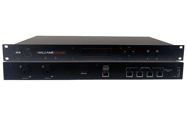
IR M1
QUICK START GUIDE
Setup Overview
1. Place your IR M1 in a location where you will be able to place the IR emitters connected to the IR M1 in the listening area.
2. Plug in the power supply to the power connection on the IR M1.
3. Connect an audio source to the Line/Mic In port for the channel(s) you’d like to use.
4. Connect an Ethernet cable to the ETHERNET port. Connect the other end of the Ethernet cable to a multicast-enabled router with an internet connection.
IR M1 MODULATOR (REAR)
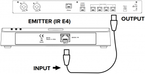
5. Connect one or more IR E4 emitters to Output to Emitter ports on the back of the IR M1 with an CAT5e cable. No additional power is required.
6. Place the emitters in the listening area so that they are above the audience without interference. Multiple emitters should be place apart from one another to expand the coverage area.
7. Turn on the IR M1.
8. On the front panel of the IR M1, a IP address should be displayed. If you do not see an IP address, check your network connection. Write it down and go to a computer. on the same network as the IR +.
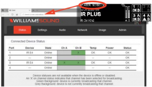
9. In Chrome or Edge, type the IP address into the URL bar. A webpage for the IR + system will load. The default usename is admin and the default password is admin.
10. Click the Audio tab and set the audio device type and desired settings for each audio channel.
11. Click the Settings tab. Configure each emitter for the channels it will broadcast, and the IR Band the system should emit.
12. Change other settings as desired.
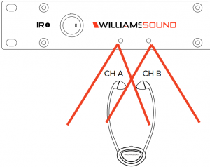
13. With your audio source playing sound, take an IR Receiver to the front panel of the IR M1. The front panel of the IR M1 has two small IR Emitters for testing, one for each audio channel. Tune the receiver to the IR Baseband channel the audio is playing on to ensure all your settings sound correct. This audio will match the audio from the IR E4 emitters.
14. For more advanced system setup, please see the full user manual.
Configuration Details
The IR M1 Modulator is the key component to the IR+ System. Audio devices, emitters and more can be connected to the IR M1. Any configuration to the IR+ system is done through the IR M1, which passes the configuration setting onto other IR+ devices.
Determine Coverage Area and Location
The modulator is usually located with the sound system amplifier or mixer for easy access to an audio input signal. For portable systems, the modulator can be placed near the emitter or in another convenient location.
The emitters will need to be placed to get the most coeverage area. When using the IR Plus system in single-channel mode with the RX22-4 receiver, the system coverage area will cover up to 18,000 sq. ft. (1,673 sq. m.) per IR E4 emitter. The IR E4 will use full power, single channel mode by default. Single channel or dual channel mode, and emitter output power, can be selected using the system webpage.
The coverage area may be affected by direct/indirect sunlight, reflections on walls and room construction. Reflections of the infrared light from walls, ceilings, and floors may change these patterns.
Important: Remember to point the emitter towards the listening audience.
Remember: Most objects block infrared light. The transmitter cannot be concealed behind walls, glass, curtains, etc.
These patterns are the direct radiation pattern. The infrared radiation does not drop to zero outside the illustrated patterns; it decreases. It still may be usable at a greater distance, depending on the receiver sensitivity and the reflective characteristics of the room.
Do not paint the front face of the IR E4.
Network Cable Connection
The Ethernet port can be used to connect the IR M1 to a local network. A network connection is required to access the IR M1 webpage. The webpage is needed to configure some device settings after the system is set up.
An Ethernet connection alone will not allow the Wi-Fi broadcast features to work; a Wi-Fi connection must be available on the network. A network connection is not required for broadcasting over infrared.
Once a connection has been established, an IP address will automatically be assigned to the IR M1. Device settings can then be set via the web interface, including changing any network settings.
NOTE: Most settings need to be set BEFORE connecting audio sources.
Cable Connection to Emitters
The IR M1 can directly drive four emitters. Emitters repeat the baseband signal, so any number of emitters can be used. The modulator outputs CANNOT be split with CAT5e splitters.
Determine the length of RJ-45 cable needed to reach from the Emitter to the Modulator unit. For more information on cabling, please read the full user manual (see “For Additional Information” on page 2).
Audio Source Connections
The IR + transmitter will accept the following audio sources:
1. Balanced Microphone with or without 12 volt phantom power (DIN 45596) on a 3-pin (XLR) connector.
2. Balanced/Unbalanced microphone with or without phantom power on 1/4 inch (TRS) jack
3. Balanced/Unbalanced Line on a 3-pin (XLR) connector.
4. Balanced/Unbalanced Line on 1/4 inch (TRS) jack.
5. Dante on an RJ-45 jack (optional).
The IR + is not designed to accept 70 volt speaker signals! This may result in damage to your system. The sound source should come directly from the system mixer or digital source as a low-level or unprocessed signal.
For specific audio wiring information, please read the full user manual (see “For Additional Information” on page 2).
Network Configuration
Network Settings can only be edited from the web interface. An IP address will be automatically assigned to the IR M1 once an Ethernet cable has been connected to the device and network connection found. Additional configuration would need to be made through the web interface.
Web Control Interface
The IR M1 provides a web interface to manage the device settings. These web pages can be accessed over either a hardwired or wireless network connection with the Chrome browser.
Changes take effect when applied or saved. Any updates made through the front panel will show up on the web interface once the current page has been navigated away from, either by refreshing the page or going to a new page.
1. Open Chrome.
2. In the address bar of the browser, type in the IP address of the IR M1 and hit Enter.
3. You should see the Login Page of the IR M1 and can adjust settings from here.
4. For more information, please read the full user manual (see “For Additional Information” on page 2).
For Additional Information
This manual is a quick start guide for getting your IR + system up-and-running. It covers basic cable connection and setup. Most features and customization options are not documented in this manual.
For additional information, feature instructions, warranty information and more, please download the full user manual from the IR Plus product pages on Williams AV’s website.
WilliamsAV IR Modulator Instruction Manual [IR M1] – WilliamsAV IR Modulator Instruction Manual [IR M1] –
[xyz-ips snippet=”download-snippet”]