
![]()
C Series Quick Start Guide
Box Contents
| • 1 x C Series Driver including:• 1 x Loop connectors (2x for C5-2, C7-2)• 1 x DC connector• 2 x Input connectors• 1 x 100V line connector• 1 x Line out connector• 2 x 2mm steel 1U rack mount brackets | • Also includes:• 1 x C Series quick start guide• 1 x Power cable (region specific)• 1 x Induction Loop Sign• 4 x self adhesive feet |
![]() This symbol is used to alert the user to important operating or maintenance instructions.
This symbol is used to alert the user to important operating or maintenance instructions.![]() The Lightning bolt triangle is used to alert the user to the risk of electric shock.
The Lightning bolt triangle is used to alert the user to the risk of electric shock.
SAFETY
- It is important to read these instructions and to follow them.
- Keep this quick start guide in an accessible place.
- Clean only with a dry cloth. Cleaning fluids may affect the equipment.
- Do not block any ventilation openings. Install in accordance with the manufacturer’s instructions.
 Do not install this equipment near any heat sources such as radiators, heating vents or other apparatus that produces heat.ERROR CLIP
- WARNING – THIS APPARATUS MUST BE EARTHED / GROUNDED.
- Only power cords with the correct power connector may be used to maintain safety. Cables incorporating the UK 13A fused plug, Schuko with earthing contacts and UL approved “grounding-type” are acceptable. These must be plugged into power outlets which provide protective earth.
- Refer all servicing to qualified personnel. Servicing is required when the apparatus has been damaged in any way, such as a power supply cord or plug is damaged, liquid has been spilled or objects have fallen into the apparatus, the apparatus has been exposed to any rain or moisture, does not operate normally or has been dropped.
- WARNING – To reduce the risk of fire or electric shock, do not expose this apparatus to rain or moisture. The apparatus shall not be exposed to dripping or splashing and no objects filled with liquids, such as vases, shall be placed on the apparatus.
- Warning: Connection to a 100V line system may involve the risk of electric shock and therefore must be carried out by an instructed or skilled person.
![]() CAUTIONRISK OF ELECTRIC SHOCK DO NOT OPEN
CAUTIONRISK OF ELECTRIC SHOCK DO NOT OPEN
TO PREVENT ELECTRIC SHOCK DO NOT REMOVE THECOVER. THERE ARE NO USER-SERVICEABLE PARTSINSIDE. REFER SERVICING TO QUALIFIED PERSONNEL
TOOLS AND EQUIPMENT
Small hand tools including a wire stripper, small flat blade, and posi screwdrivers will be required.A magnetic field strength meter, Loop works Measure App & R1 Reciever, or at minimum, an induction loop receiver is vital to check that the loop system is providing the desired level of performance.
INPUTS AND OUTPUTS
The driver has two inputs labeled 1 and 2. Each input can be separately configured to mic or line signal level using a rear panel push switch. Global 24V phantom power can be enabled to supply any input set to the mic level. Alternatively, input 2 can accept a100V line using a dedicated 2 pin socket. Do not use both input 2 sockets at the same time.
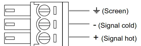
Figure 1: Input connections
![]() Do not run input and output cables close together
Do not run input and output cables close together
![]() Warning: Connection to a 100V line system may involve the risk of electric shock and therefore must be carried out by an instructed or skilled person.The driver has two loop outputs labeled Loop A and Loop B. In order to achieve correct operation, it is recommended the loop and feed resistance should be between 0.2 and 10Ω (at DC).
Warning: Connection to a 100V line system may involve the risk of electric shock and therefore must be carried out by an instructed or skilled person.The driver has two loop outputs labeled Loop A and Loop B. In order to achieve correct operation, it is recommended the loop and feed resistance should be between 0.2 and 10Ω (at DC).
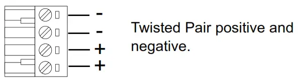
Figure 2: Output connections
SETTINGS
The C Series drivers have their adjustments set in decibels (dB). A setting of 0dB equates to maximum current or to maximum input gain. A negative value will reduce the current or input gain accordingly.
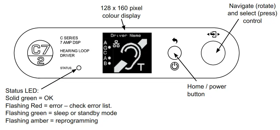
Figure 3: Front panel display and control
From the factory the drivers are provided with the following setting:
- Current: -20dB from full output
- Metal Loss Compensation (MLC) OFF
- Input Gain Channel 1 -80.0dB
- Input Gain Channel 2 -80.0dB
- Driver Name “Name not set”
- Phase Shift ON
- Ethernet Parameters Set by DHCP
ADDITIONAL FEATURES
- Home screen timeout – if no action is taken in a mode screen after the 30s the home screen is displayed. For a value screen, the timeout is the 60s.
- Sleep mode – After a 10 minute period of the user or audio inactivity the driver turns on the ‘Loop outputs disabled’ test signal and turns off the screen to save power. The Status led flashes green to indicate this.Any user activity or presence of an audio signal brings the driver out of sleep. The inactivity time can be changed via the website (where network option fitted)
- Lock screen – A long press on the home button brings up the lock menu. This gives access to standby, re-start (same as in settings menu) & lock. Selecting lock makes the user controls inactive. Any user input results in a padlock being displayed. To unlock the unit press the home button six times. Unlock instructions are shown briefly when the lock is selected.
- Standby – This is a user-imposed sleep. Only user activity (not audio signal) brings the driver out of standby.
NETWORK CONNECTION (OPTION)
Where fitted C Series drivers feature a web interface that can be viewed in a web browser. Although optimized for the Chrome browser, any browser can be used to view the interface. The web interface is used to monitor and adjust the driver. You will be asked for the User Name and Password for the driver as a deterrent to unauthorized parties. These values are case-sensitive and need to be entered once per session to access the driver.
User Name = superadmin, netadmin, audioadminPasswords = aneutronic (default)
Four levels of access are available:
- superadmin – allows access to all settings
- net admin – access the network settings page only
- audio admin – access the audio settings pages only
- no login – allows access to a status page
TROUBLESHOOTING
OUTPUT A / B OPEN CIRCUIT:The driver has detected that the loop connected to A / B out is too high an impedance.HEATSINK TOO HOT PLS SWITCH OFF: The driver’s heatsink has reached a critical temperature and the driver must be switched off.The following error messages all indicate an error in the internal circuitry of the driver. Please contact Ampetronic technical support if any of these errors are seen, quoting the error message text.OUT A / B IDLE OVERCURRENTOUT A / B FUNC TEST HIGH OVERCURRENTOUT A / B FUNC TEST LOOPS CROSSWORDThese error messages indicate a possible error with the loop or the connections to the loop:LOOP A / B R < 200mR FIX AND RESTART: The driver measured < 200mR for the loop impedance.This is too low for the driver and must be fixed before the driver will finish the start-up diagnostics. Switch off, fix the fault and switch on again.LOOP A / B > 10R LOOP COULD CLIP: The loop is not an open circuit but has a resistance of > 10R.This is too high and the driver will clip on output peaks. This is a warning and the driver will continue after 5 seconds.CHANNEL A / B OPEN CIRCUIT: This message is displayed if the loop is disconnected whilst the driver is operating (e.g. if a carpet fitter cuts the loop). The message is displayed on the front panel for 5 seconds and on the web interface.These are information messages and do not indicate an error:DIAGNOSTICS IN PROGRESS: This message is displayed on the front panel whilst the start-up tests are being performed.New IP Address XXX.XXX.XXX.XXX A new Ethernet address has been assigned to the driver. This can occur when an Ethernet cable is plugged into the driver or the DHCP system re-assigns a new IP address.
These messages appear in the status menu when the associated error is present:
| Power Limit – derated:Loop A open circuit:Loop B open circuit:Temp Limit – derated:Temp Limit – mutedChannel A Clipping:Channel B Clipping: | The driver is overloaded and the drive current has been reducedThe driver has detected an open circuit on loop A.The driver has detected an open circuit on loop B.The internal heatsink is too hot and the driver current on both channels has been reduced.The internal heat sink has reached an unacceptable level and outputs have been turned off.The driver output maximum voltage is being exceeded and the loop A signal is being clipped.The driver output maximum voltage is being exceeded and the loop B signal is being clipped. |
ASSOCIATED DOCUMENTS
 report this ad
• UP19801 – C Series Installation Handbook & User Guide• UP39801 – C Series DatasheetAssociate documents are available as a download from www.aneutronic.co, in Loop works Learn or can be requested by contacting [email protected] / +44 (0) 1636 610062
WARRANTY
This product carries a five-year parts and labor warranty from the date of shipment from Ampetronic. To qualify for the five-year warranty, the product must be registered at www.ampetronic.co (products/warranty), without which the warranty will be valid for two years only. The warranty could be invalidated if the instructions in this handbook are not followed correctly, or if the unit is misused in any way.
DECLARATION OF CONFORMITY
Manufacturer:Ampetronic Ltd.Unit 2, Trentside Business Village, Farndon Road, Newark,Nottinghamshire, NG24 4XB, United Kingdom.
Declares that the product:
| Description:Type name: | Hearing / Induction Loop DriverC Series |
in accordance with the following directives, conforms to the following Directive(s) and Norm(s):
| 2014 / 35 / EU2014 / 30 / EU2011 / 65 / EU | The Low Voltage Directive and its amending directivesThe Electromagnetic Compatibility Directive and its amending directivesThe RoHS Directive and its amending directives and has been designed and manufactured to the following specifications: |
Safety Standards:
| EN 62368-1 / UL 62368-1 | Audio, video and similar electronic apparatus – Safety requirements |
EMC Standards:
| EN 55032EN 55035 | EMC – Product family standard for multimedia equipment: EmissionEMC – Product family standard for multimedia equipment: Immunity |
Date: August 2018
J.R. PietersManaging Director,Ampetronic Ltd.![]() CAUTION: Changes or modifications not expressly approved by Ampetronic or an authorized partner could void the user’s authority to operate the equipment.NOTE: This equipment has been tested and found to comply with the limits for a Class A digital device, pursuant to Part 15 of the FCC Rules. These limits are designed to provide reasonable protection against harmful interference when the equipment is operated in a commercial environment. This equipment generates, uses, and can radiate radio frequency energy and, if not installed and used in accordance with the instruction manual, may cause harmful interference to radio communications. Operation of this equipment in a residential area is likely to cause harmful interference in which case the user will be required to correct the interference at their own expense.
CAUTION: Changes or modifications not expressly approved by Ampetronic or an authorized partner could void the user’s authority to operate the equipment.NOTE: This equipment has been tested and found to comply with the limits for a Class A digital device, pursuant to Part 15 of the FCC Rules. These limits are designed to provide reasonable protection against harmful interference when the equipment is operated in a commercial environment. This equipment generates, uses, and can radiate radio frequency energy and, if not installed and used in accordance with the instruction manual, may cause harmful interference to radio communications. Operation of this equipment in a residential area is likely to cause harmful interference in which case the user will be required to correct the interference at their own expense.
reserved. rights All 2018. Ampetronic Ltd © Copyright -2 Contents UP19802
References
[xyz-ips snippet=”download-snippet”]