
WISDOM Sage Series SUB1 Installation and Owner’s Manual
![]()
Minimal Appearance Subwoofer
Preconstruction Mounting
Gypsum and Solid Surface Mounting Final Installation
Document Conventions
This document contains general safety, installation and operation instructions for the Wisdom Audio Sage Series Minimal Appearance loudspeakers. It is important to read this document before attempting to use this product. Pay particular attention to:
WARNING: Calls attention to a procedure, practice, condition or the like that, if not correctly performed or adhered to, could result in injury or death.
CAUTION: Calls attention to a procedure, practice, condition or the like that, if not correctly performed or adhered to, could result in damage to or destruction of part of or the entire product.
Note: Calls attention to information that aids in the installation or operation of the product.
System Overview
Connections
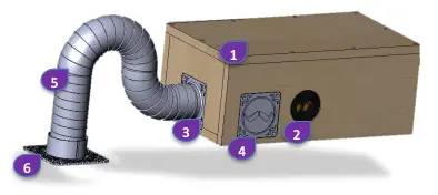
- Band-Pass Cabinet
- Speaker Termination Binding Posts
- Primary Bass Snorkel Port Tube Output
- Alternate Bass Snorkel Port Tube Output
- Bass Snorkel Port Tube
- Bass Snorkel Attachment to Mounting Platform (Mounting Platform)
NOTE: Bass Snorkel Tube length is not to be altered as it will severely impact the operation of the subwoofer.
What is Included
- Band-Pass woofer assembly box for installing into the ceiling joists
- The “Bass Snorkel”
- Two (2) band clamps
- L-bracket for mounting band-pass cabinet to joists with
Required Accessories Not Included
- Surface Mount Kit is available for gypsum ceilings using 1/2” or 5/8” (13mm or 16mm) drywall thickness and for solid surface installation for all materials such as stone, wood or tile, from 3/8” to 1-1/4” (9.5mm to 32mm) thickness. A routing tool is also available to help cut solid surface installations.
- Grills are available in 3” or 4” (76mm or 102mm) width and in both square and round to match lighting fixtures.
Mounting the SUB1 Cabinet into the Ceiling Joists
The SUB1 comes shipped with four (4) L brackets. The brackets should be located at the front and rear of the cabinet. The long edge should be screwed into the cabinet. The bracket has a slot to allow for adjustment to allow for a tight fit to the joists.
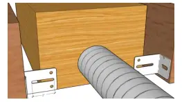
- Lay the SUB1 on a flat work surface to allow the bottom of the bracket to sit flush with the bottom of the SUB1.
- Using the short screws, screw the long edge of the bracket into the face of theSUB1, but do not overtighten!
- Measure the width of the opening between the joists where the SUB1 will be located and adjust the width of the bracket. Use a second short screw and screw through one of the holes in the bracket, and hand tighten all screws.
- With the help of an assistant, hold the SUB1 in place so that the L-Brackets (and bottom of the SUB1) is approximately 1/8” (3mm) above the bottom of the joist. This will allow a small air gap between the SUB1 and the ceiling.
- Using the long screws, attach the L-Bracket to the joists.
NOTE: The bottom of the cabinet should not touch the ceiling gypsum to reduce unwanted rattles and resonances.
QuickStart Installation Guide
The installation of the SUB1 can be broken down into several simple steps. The installation of the SUB1 is intended to be a pre-construction process as it requires access to the space within the ceiling joists. The SUB1 fits within standard ceiling joists that are spaced between 12” to 24” OC (305mm to 610mm) and requires a minimum of 8” (203mm) of height to fit the box plus the L brackets.
NOTE: Bass Snorkel Tube length is not to be altered as it will severely impact the operation of the subwoofer.
- Identify subwoofer locations. Identify the surface to be mounted, and the size and shape of the finished grille.
- The SUB1 band-pass must be located within 12” to 24” (305mm to 610mm) of the grille location for the snorkel.
- Mount the L-brackets to the joists where the band-pass cabinet will be located as detailed above.a. The brackets should be positioned to support the front and rear of the cabinet.b. If necessary, use the SUB1 shipping foam to remove excess space inside the joists.
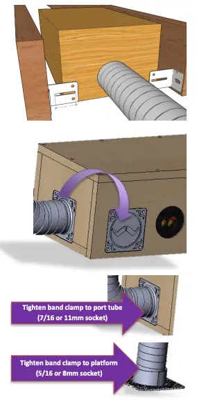
- Position the band-pass cabinet between the joists so that you have access to the speaker binding posts and port tube outlet.a. The port tube “Bass Snorkel” can be repositioned from the front to the side of the cabinet if access to the port tube will be obstructed.b. The port tube connection and the block off plate are held in plate with screws and can be easily.
- Connect the speaker wires to the binding posts on the side of the cabinet.
- Connect the “Bass Snorkel” port tube to the cabinet with steel clamp.
- Connect the “Bass Snorkel” to the mounting platform with the neoprene rubber under steel clamp. The clamp should fit snug before being tightened. If not, flip the clamp and check again. The inside of the clamp has slightly smaller inside dimensions for the side to be used with the snorkel and slightly larger inside dimension for the side to be used with the mounting plate.
- For Gypsum installations, mud using the Sanding Guide. Once the sanding is complete, push firmly on the sanding shield to break any adhesion to surrounding surfaces. Remove the screw in the center of the shield under the tape. This will expose the paint shield. Do not remove the paint shield.
- For Gypsum installations, use the Paint Shield to allow the paint to fill the inside corner where the grille will be placed.
- Adjust the grille depth for a flush mount to the finished surface using the Paint Shield as a guide.
NOTE: The SUB1 port tube clamp is not accessible from within the room and must be tightened before drywall is finished.
Grill Depth Adjustment
These instructions are for ceilings that have been finished and painted. The system is now ready to have the grille plane set using the Magnetic Recoil Fastener (Pat. Pend). and the grille secured in place. Use the Paint Shield to set the plane of the grille as it has access holes for the adjustment screws so the depth can be adjusted with ease. Adjust the depth as necessary by using the screws of the Grill Catch and the Paint Shield as a reference guide. The Paint Shield is the same thickness as the grille.
Step 1: If not already done, remove the Sanding Guide. It is held to the Painting Shield with a small screw under protective tape and should be removed before painting the ceiling. Press slightly to remove any excess drywall and break the attachment, then remove screw and pull up with a pick tool.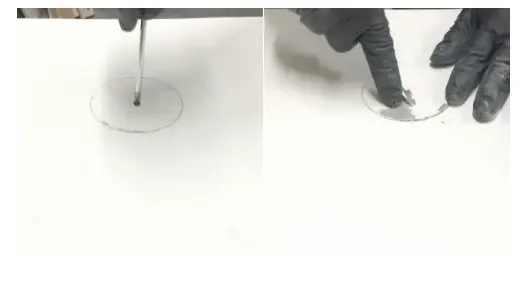
Step 2: The Paint Shield has three access cutouts for the three adjustment screws underneath. The Paint Shield is the same depth as the Grill. Adjust the screws for a flush fit.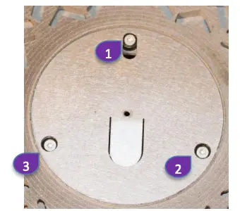
Step 3: Remove the Paint Shield to expose the Subwoofer Grill Catch which has now been adjusted for depth. The exposed adjustment screws of the Magnetic Recoil Fastener (Pat. Pend) can be seen below.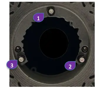
Step 4: Place the grille on the magnetic Grill Catch.Done!
Grill Painting (Optional)
- Prime the grille with a metal primer/bonder in a spray can. Carefully follow the manufacturer’s directions on the can.
- We recommend using water-based latex paint on the grilles. Thin the paint with a proper thinning agent to a ratio of 1:1 paint-to-thinner, and strain it through a standard mesh strainer to remove any lumps. IMPORTANT: Due to its increased durability, oil-based paint should be considered for any installation where the grilles may be exposed to moisture.
- Use a small touch-up gun or cap-spray gun with a #3 tip for painting.a. Set the nozzle with a medium to wide fanb. Set the pressure regulator to 60psic. Lightly spray the front of the grille in 3 quick strokes from approximately 10 inches awayd. Let the paint set for a minute, then turn the grille 90° and lightly spray the grille again in 3 quick strokes. Repeat this step until al l four sides of the grille have been evenly painted evenly.
- While the paint is still wet, inspect the grille and make sure that excess paint has not collected underneath the grille frame, and that none of the grille perforations are filed with paint. If any are, use compressed air to blow the paint out of the perforations.NOTE: If you find any grille perforations that are plugged with paint after the paint has dried, use a straight pin or sewing needle to carefully remove the paint.
- Once the paint has thoroughly dried, mount the grille on the speaker.
Crossover and Amplifier Recommendations
The SUB1 subwoofer is optimized for use with the ICS3 speakers, with a bass-management crossover of 120Hz 4 th order Linkwitz– Riley, and with a high-pass filter of 30hz 4th order Linkwitz-Riley. The SUB1 in-ceiling Minimal Appearance subwoofer is designed to work seamlessly with the ICS3 when used with a Wisdom Audio SC-2 or SC-3 system controller, or other processor capable of implementing the correct crossover between for the ICS3.
We recommend using a high-performance Wisdom Audio SA amplifier or comparable with between 100-300 watts per channel.
Care & Maintenance
To remove dust from the front of your SUB1, use a feather duster or a lint-free soft cloth.
To remove stubborn dirt and fingerprints from the grille, we recommend isopropyl alcohol and a soft cloth. Lightly dampen the cloth with alcohol first and then clean the grille with the cloth. Do not use excessive amounts of alcohol—there is no need for the cloth to be wet; merely damp is better. Never attempt to clean the drivers themselves.
North American Warranty
Standard Warranty
When purchased from and installed by an authorized Wisdom Audio dealer, Wisdom Audio loudspeakers are warranted to be free from defects in material and workmanship under normal use for a period of five years from the original date of purchase.
Furthermore, the transducers (“drivers”) in your Wisdom Audio speakers are warranted to be free from defects in material and workmanship under normal use for a period of ten years from the original date of purchase.
Harsh Conditions Use
The Sage Series loudspeakers are designed for installation and operation in environmentally controlled conditions, such as are found in normal residential environments. When used in harsh conditions such as outdoors or in marine applications, the warranty is three years from the original date of purchase.
During the warranty period, any Wisdom Audio loudspeaker exhibiting defects in materials and/or workmanship will be repaired or replaced, at our option, without charge for either parts or labor, at our factory. The warranty will not apply to any Wisdom Audio loudspeaker that has been misused, abused, altered, or installed and calibrated by anyone other than an authorized Wisdom Audio dealer.
Any Wisdom Audio loudspeaker not performing satisfactorily may be returned to the factory for evaluation. Return authorization must first be obtained by either calling or writing the factory prior to shipping the component. The factory will pay for return shipping charges only in the event that the loudspeaker is found to be defective as mentioned above. There are other stipulations that may apply to shipping charges.
There is no other express warranty on this loudspeaker. Neither this warranty nor any other warranty, express or implied, including any implied warranties of merchantability or fitness, shall extend beyond the warranty period. No responsibility is assumed for any incidental or consequential damages. Some states do not allow limitations on how long an implied warranty lasts and other states do not allow the exclusion or limitation of incidental or consequential damages, so the above limitation or exclusion may not apply to you.
This warranty gives you specific legal rights, and you may also have other rights, which vary from state to state. This warranty is applicable in North America only. Outside of North America, please contact your local, authorized Wisdom Audio distributor for warranty and service information.
Obtaining Service
We take great pride in our dealers. Experience, dedication, and integrity make these professionals ideally suited to assist with our customers’ service needs.
If your Wisdom Audio loudspeaker must be serviced, please contact your dealer. Your dealer will then decide whether the problem can be remedied locally, or whether to contact Wisdom Audio for further service information or parts, or to obtain a Return Authorization. The Wisdom Audio Service Department works closely with your dealer to solve your service needs expediently.
IMPORTANT: Return authorization must be obtained from Wisdom Audio’s Service Department BEFORE a unit is shipped for service.
It is extremely important that information about a problem be explicit and complete. A specific, comprehensive description of the problem helps your dealer and the Wisdom Audio Service Department locate and repair the difficulty as quickly as possible.
A copy of the original bill of sale will serve to verify warranty status. Please include it with the unit when it is brought in for warranty service.
WARNING: All returned units must be packaged in their original packaging, and the proper return authorization numbers must be marked on the outer carton for identification. Shipping the unit in improper packaging may void the warranty, as Wisdom Audio cannot be responsible for the resulting shipping damage.
Your dealer can order a new set of shipping materials for you if you need to ship your loudspeaker and no longer have the original materials. There will be a charge for this service. We strongly recommend saving all packing materials in case you need to ship your unit someday.
If the packaging to protect the unit is, in our opinion or that of our dealer, inadequate to protect the unit, we reserve the right to repackage it for return shipment at the owner’s expense. Neither Wisdom Audio nor your dealer can be responsible for shipping damage due to improper (that is, non-original) packaging.
Specifications
Note: All specifications are subject to change at any time, in order to improve the product.
Frequency response: 37Hz – 140 Hz +/- 3dBImpedance: 8 ohmsSensitivity: 85dB SPL (2.83V @ 1m)Recommended Amplifier Power: 100 WattsMaximum Amplifier Power: 300 WattsDimensions HxWxD: 7.9” x 10.5” x 19.25” (20.066cm x 26.67cm x 48.895cm)Port Tube Length: 3″ x 24″ (7.62cm x 60.96cm)Recommended High Pass Crossover: 30Hz 24dB Linkwitz–RileyRecommended Low Pass Crossover: 120Hz 24dB Linkwitz–Riley
Designed to fit within minimum 2” x 8” (50mm x 200mm) ceiling/floor joist between 12” – 24” ( 305mm – 610mm) OC.
WISDOM and the stylized W are registered trademarks of Wisdom Audio.
Magnetic Recoil Fastener (Pat. Pend).
Wisdom Audio 1572 College Parkway, Suite 164Carson City, Nevada 89706 USATelephone: 775.887.8850Fax: 775.887.8820www.wisdomaudio.com
![]()
 report this ad
SUB1OM-1.0 © 11/17/2020Wisdom Audio, Inc. All rights reserved.Printed in U.S.A.
References
[xyz-ips snippet=”download-snippet”]