WISDOM Solid Surface Mounting Kit Owner's Manual

Document Conventions This document contains general safety, installation and operation instructions for the Wisdom Audio Sage Series Minimal Appearance loudspeakers. It is important to read this document before attempting to use this product. Pay particular attention to: WARNING: Calls attention to a procedure, practice, condition or the like that, if not correctly performed or adhered to, could result in injury or death. CAUTION: Calls attention to a procedure, practice, condition or the like that, if not correctly performed or adhered to, could result in damage to or destruction of part of or the entire product.
Note: Calls attention to information that aids in the installation or operation of the product.
Sage Series Minimal Appearance System Ordering and Planning
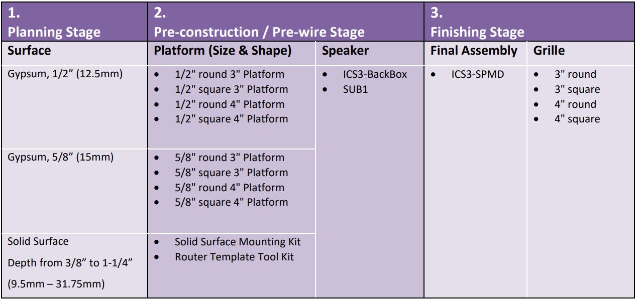
Solid Surface Mounting Kit
Preparing for Solid Surface Mounting
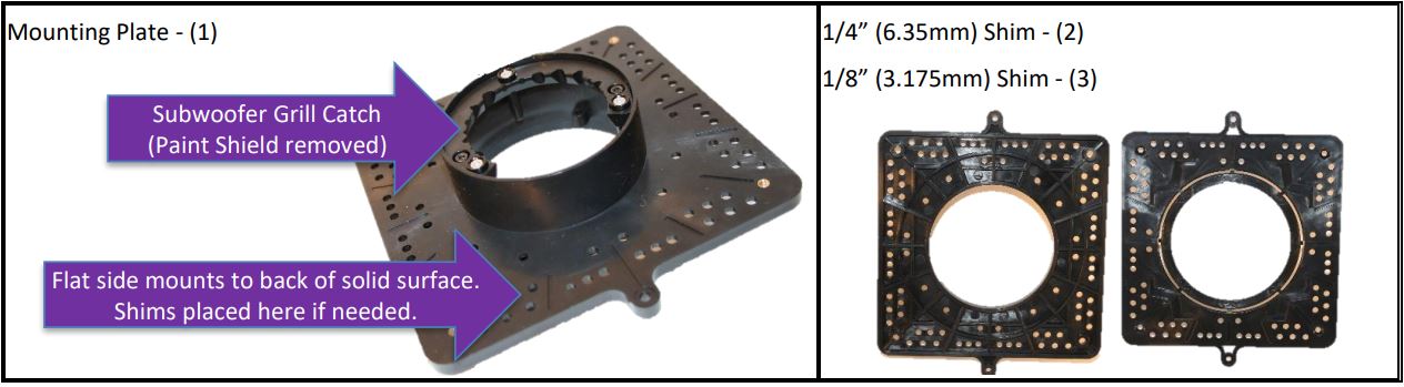
Included Parts
Depending on the size and shape of the cutout the dimensions of the mounting shims and accessories will change, but the instructions to install are the same. There are several parts to allow proper adjustment for a fully flush mount speaker to be properly installed.
- ICS3-Backbox Mounting Plate / Subwoofer Port Tube and Grille Catch
- Mounting Ring Shim 1/4″ (6.35mm) Shim – (2 included)
- Mounting Ring Shim 1/8″ (3.175mm) Shim – (3 included)
Note: The Mounting Plate has a floating magnet ring that can be adjusted up or down to allow for the grill to fit perfectly flush with the ceiling. This is done with the 3 set screws inside the Mounting Plate. Adjust this when the grill is installed for a perfect fit.
Accessories and Supported Options
The solid surface mounting kit can be used with both ICS3 and SUB1 installations. Make sure you have the correct speaker preconstruction and final assembly parts for the installation.
- ICS3-Backbox with mid-bass driver for pre-construction and ICS3-SPMD (Spiral Planar Magnetic Driver) final assembly
- SUB1 band-pass box (pre-construction)
- Grille Options
- 3″ (76mm) Square Grill
- 4″ (102mm) Square Grill
- 3″ (76mm) Round Grill
- 4″ (102mm) Round Grill
Installation and template tool accessories for customized cutting of the mounting material have been combined into one complete toolkit. Only one (1) needs to be purchased and can be re-used for multiple jobs.
- Routing Template & Tool Kit, includes all configurations:
- 3″ (76mm) Round and 3″ (76mm) Square Routing Template
- 4″ (102mm) Round and 4″ (102mm) Square Routing Template
- Router Collar: 5/8″ and 3/8″ (3/8″ is only used with 3″ openings)
- Router Bits: 1/4″ (Up Cut/spiral) x2
Tools Needed for Routing Template
Two tooters are suggested for use with the 3″ round and 3″ square template for quickly cutting multiple mounts without needing to reset the tool. Only one router is needed for 4″ size. At least one router with the ability to install a template bushing in the base is required. A plunge cut router is recommended for easiest cutting of the opening but is not required.
ICS3 Prewire and Pre-Construction Preparation
For ICS3 the only preparation before mounting the speakers with the prepared solid surface is to pre-wire as you normally would. The ICS3-Backbox with mid-bass driver will be attached to the rear (in-ceiling) solid surface after correct cutout and shim installation and installed as one unit. The ICS3-SPMD (Spiral Planar Magnetic Driver) can be installed either during or after installation of the solid surface.
SUB1 Prewire and Pre-Construction Preparation
The SUB1 bass driver and band-pass box with port tube need to be installed and prewired before installing the solid surface platform. No access to the band-pass box is possible after the solid surface is installed. Install the band pass box between 12″ and 24″ from where the grill location cutout will be and ensure the port tube is fully installed on the band-pass box before continuing. The bass tube must also be attached to the back of the mounting plate before fully closing the ceiling as no access to the bass port tube is possible from in the room. NOTE: Bass Snorkel Tube length is not to be altered as it will severely impact the operation of the subwoofer.
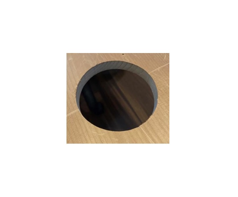
Cutting the Solid Surface
Depending on what type of material the speaker is being mounted into, there are a variety of different methods that can be used to cut the grille opening. For harder, dense materials, such as stone or tile, the use of a water jet machine is required. For softer materials, such as wood, a CNC table or a router template accessory can be used. Whichever method is used, the opening must be cut very precise. Unlike traditional speaker grilles, Minimal Appearance grilles do NOT cover the opening that is cut into the material – they install flush to the material surface, therefore leaving zero tolerance for uneven, or unclean cuts in the opening.
Below are instructions for the two options, (1) Water Jet / CNC and (2) Router Template. The router template can be purchased from Wisdom Audio.
Method 1: Water Jet / CNC Using CAD
Water Jet / CNC Step 1: Send File
Most stone suppliers will have access to a water jet machine. Locate a water jet machine at a local stone supplier, or contact the stone supplier for the job, and send the Minimal Appearance water jet files. The water jet files are a .DXF file that contains the tool path needed for a precise and consistent grille opening. These files can be found at www.wisdomaudio.com.
Water Jet / CNC Step 2: CutUsing CNC, the cutting portion of the process will be done offsite by another tradesperson. Once the completed piece is returned to the jobsite, continue with the final installation of the solid surface shims as shown in the next section.
Method 2: Using the Optional Router Template
Step 1: Measure
Measure the center point of the grill opening in the finished location using the Mounting Plate as a guide. This is a critical measurement as the center of the grill opening and all alignment if the placement is based on this measurement.
Step 2: Mark
With the material laying FACE DOWN on a sturdy work surface, mark the center point of the grille opening on the material based on the measurement in Step 1.
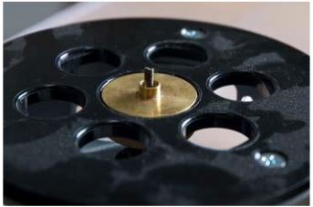
Step 3: Setup Router
The following tools will be needed to route the opening:
- Router 1: 1/4″ Bit with 5/8″ Bushing
- Router 2: 1/4″ Bit with 3/8″ Bushing (for 3″ opening only)
- Appropriate clamps to secure wood and template.
- Drill to start the opening for the router and Jig Saw to rough cut are options you may want to use but are not necessary.
(Bottom of the Router with bushing and bit installed)
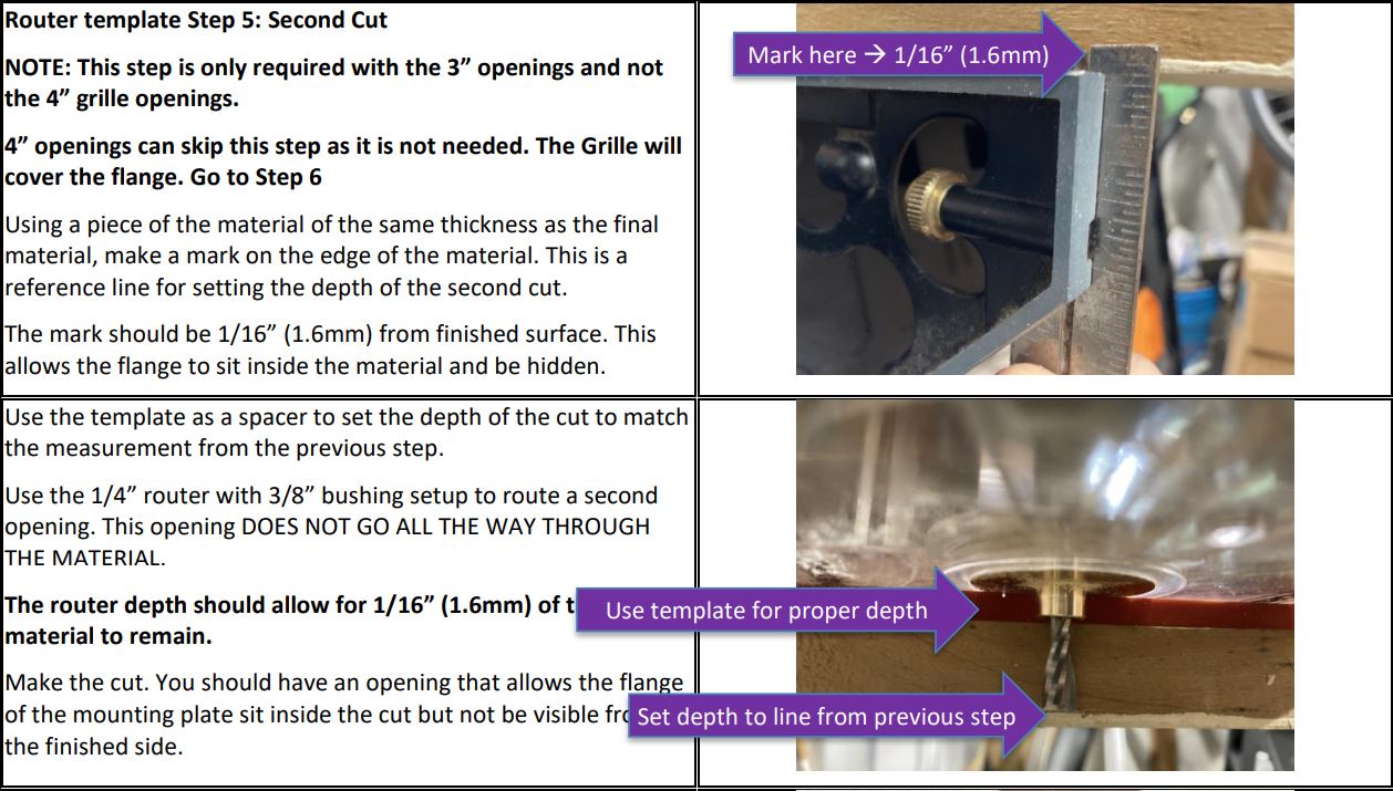
Router Template Step 4: Grill Opening Cut
Place the router template on the surface of the material and center it on the center point. Secure it to the material with clamps. Next, using the 1/4″ router bit with 5/8″ bushing, route around the opening in the router template.
Make sure the depth of the bit is set to clear the material being cut. Making two passes may be needed for thicker material.Do not remove template until final cut is completed!!! For 4″ openings, skip to Step 6
First Cut for Grille Opening (template removed for clarity)
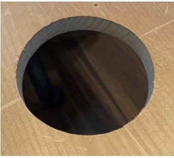
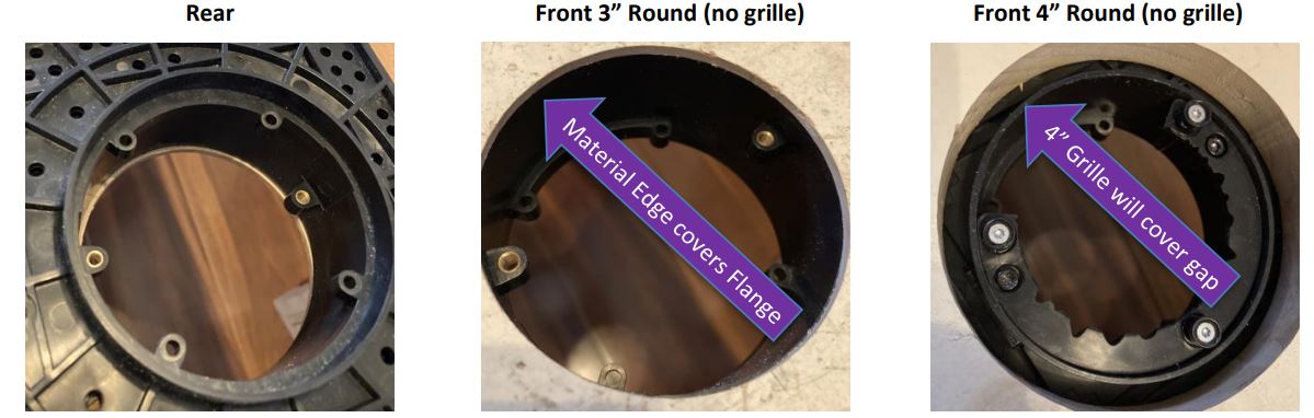
Step 6:Check the fit of the mounting plate and grille into the opening and adjust the cutout opening as needed!!!For 3″ openings the mounting flange should be covered by the wood and the grilles should fit just inside the smaller opening.For 4″ openings there is only one cut and only the grille opening needs to be checked for fit.

Selecting and Installing Shims and Mounting Plate
After the opening has been cut in the solid material, the Mounting Plate and shims (if needed) are installed to the back (in-ceiling) of the solid surface. To allow for the speaker grill to fit completely flush the Solid Surface Mounting Kit comes with (2) 1/4″ thick shims and (3) 1/8″ thick shims to be used with the Mounting Plate.The Mounting Plate has a magnetic paint shield (installed from the factory) with 3 holes that line up with the 3 screws of the Magnetic Recoil Fastener (Pat. Pend) and is the same thickness as the grill. Do not throw this out until after you have adjusted the height adjustment for the grill to sit flush.The Mounting Plate includes a crescent shaped grill catch that is only used with the SUB1 port tube. This grill catch is removed for the ICS3-SPMD installation during final assembly.
NOTE: The shims have mounting tabs that can be removed as needed to fit into different shapes and sizes. Trim as needed.
![]()
Attach Mounting Plate to Solid Surface
Once the correct number of shims are selected for the finish material, the mounting ring shim(s) can be fastened to the mounting ring before attaching it to the finish material.
To attach the mounting ring to the finish material you can use either or epoxy/glue or screws. The method that you select depends on the type of material speaker is being attached to. Below are the instructions for both methods.
Step 1 Align
Lay the correct number of mounting ring shims on the front side of the mounting ring.
Step 2 Attach
Attach to the mounting ring with screws provided.
Step 3 Check for Fit and FlushBefore attaching the mounting ring to the finish material, be sure the alignment fixture is positioned on the face of the mounting ring. With the material positioned face down on a sturdy, flat, and clean work surface, place the mounting ring onto the backside of the material. The mounting ring should be tight within the speaker opening.
Step 4a Option 1: Epoxy Attachment
With the mounting ring separate from the material, clean with acetone both the backside of the material where the flange will rest and the flange of the mounting ring. Next, apply thin layer of epoxy to the material surface and a generous layer to the flange. Then, place the mounting ring in the opening and press firmly so that the flange rests securely against the material.
Step 4b Option 2: Screw Attachment
With the material positioned face down on a sturdy, flat, and clean work surface, place the mounting ring on the back side of the finish material. Select the outermost holes on each of the mounting ring’s four sides and drill a pilot hole into the material. Then, using four appropriately sized screws, fasten the ring to the material.The solid surface is now ready for final assembly and then to be installed into the speaker location.
Final Installation Into Ceiling
• ICS3 Final Assembly and Installation Steps:
- For ICS3 you must screw the ICS3-Backbox onto the Mounting Plate and connect the speaker wires.
- After the ceiling is finished (painting, sanding or other finish work) the ICS3-SPMD is installed.
- The SUB1 grille catch is removed from mounting plate and the ICS3-SPMD is screwed in using the same mounting screws.
- Installing the ICS3-SPMD can be done at the end of the install, or when placing the completed back-box platform into the ceiling. Care should be taken not to damage the ICS3-SPMD.
- After the ICS3-SPMD is installed, use the paint shield to adjust the depth of the grille as shown below.
- There is a protective plastic shipping cover the ICS3-SPMD that should be removed before playing audio.
• SUB1 Final Assembly and Installation Steps:
- For SUB1 you must connect the port tube from the SUB1 band-pass box to the Mounting Plate.
- After the mounting platform is installed the grille depth can be set using the paint shield to adjust the depth of the grille as shown below.
ICS3-Backbox Attachment to Platform
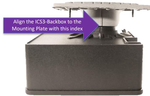
Attach ICS3-Backbox to platform first. The ICS3-Backbox attaches to the Mounting Plate using 4 screws. The back-box and the Mounting Plate have a keyed connection and can only fit one way.
Remove the Paint Shield.
It may be easier to remove the SUB1 Grill Catch from the Mounting Platform to gain access to all 4 screws, but it is not necessary if you are careful!
DO NOT THROW AWAY THE PAINT SHIELD!Locate the four screw locations on the mounting plate and line them up to the four screw holes on the back box. Once in place, secure with the screws included in the ICS3-Backbox.
Replace the Grill Catch, Sanding Guide and Paint Shield.
ICS3-SPMD (Spiral Magnetic Planar Driver) Installation Into ICS3-Backbox:
NOTE: You should have already installed the ICS3-Backbox with Solid Surface Mounting Platform to use these instructions and have completed sanding and painting of the ceiling. The ICS3-SPMD should be protected from dust and paint during construction.
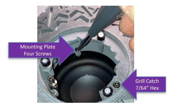
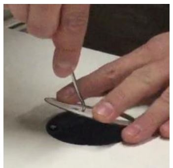
Step 1: Remove the Paint Shield by inserting a pick tool into the cut out of the steel Paint Shield and gently pulling the Paint Shield away from the assembly, it is held on magnetically.
NOTE: Keep the paint shield to use during the grille depth adjustment at the end.
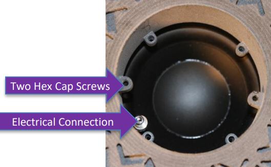
Step 2: This will expose the Subwoofer Grille. Remove the Subwoofer Grille Catch by removing the (2) #6-32 cap screws using a 7/64″ hex head screwdriver bit. The Subwoofer Grille Catch should be free to remove from the Mud Plate.
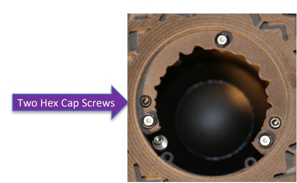
Step 3: Install the Spiral Planar Magnetic Driver (ICS-SPMD). The ICS3-SPMD can only be inserted in one way to make the electrical connection.
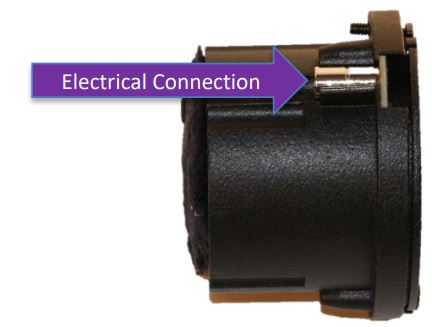
Step 4: The electrical connection to the ICS3-SPMD is mated by securing the ICS3-SPMD to the ICS3-Backbox. Insert the (2) #6-32 hex drive cap screws through the ICS3-SPMD and into the mounting bosses of the Mounting Platform.
Step 5: Check for tight fit (hand tighten only!)NOTE: There is a protective plastic film on the ICS3-SPMD. Do not remove it until after you have completed installation.

Step 6: Replace Paint Shield for setting the grille depth (next section)

SUB1 Port Tube Connection
Attach to the rear of the Clamping Plate using the screw down collar. Tighten the clamps on both ends of the port tube.
The clamp should fit snug before being tightened. If not, flip the clamp and check again. The inside of the clamp has slightly smaller inside dimensions for the side to be used with the snorkel and slightly larger inside dimension for the side to be used with the mounting plate.
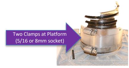
Tighten the single clamp on the band-pass cabinet outlet.Take care not to kink the tube. The minimum distance needed to make a 90-degree bend is 4-1/2 inches (115mm).
NOTE: Bass Snorkel Tube length is not to be altered as it will severely impact the operation of the subwoofer.

At this time, you can install the complete assembly into the ceiling joists. Once all wires are connected to the SUB1 band-pass box the panel can be installed into the ceiling. Final ICS3-SPMD installation and grille depth is adjusted using the paint shield (see below).
Using Paint Shield to Adjust Grille Flush and Level
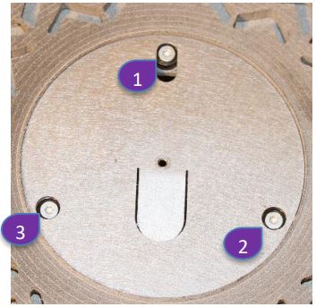
The paint shield is held in place with magnets and has access holes for three (3) adjustment screws as part of the Magnetic Recoil Fastener (Patent Pending). The paint shield is the same thickness as the speaker grille that will be installed at the end of the installation. Use the paint shield to adjust the three screws for a perfectly level and flush installation. For the SUB1 this can be done as soon as the painting is completed.
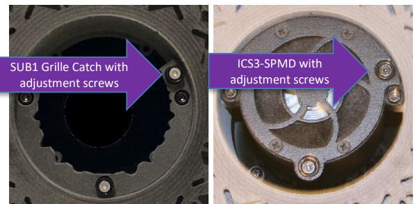
NOTE For ICS3: The paint shield and Sub1 grille catch will be removed for the ICS3-SPMD to be installed. The paint shield must be kept for adjustment of the grille depth. The ICS3-SPMD is installed after painting is completed. To install the SPMD the SUB1 Grill Catch must be removed first.
NOTE For SUB1: The paint shield is used to set the final grille depth. Do not throw away until after grille depth is set. For the SUB1, grille adjustment can be made once painting is completed as the SUB1 Grill Catch is pre-installed and has the Magnetic Recoil Fastener (Pat. Pend).
Adjust Grill Mounting Depth: ICS3
The paint shield is held in place with magnets and has three holes that allow access to the three set screws. Save the metal paint shield while installing the ICS3-SPMD. After installing the ICS3-SPMD and before installing the grille, use the paint shield to set the depth of the 3 set screws of the Magnetic Recoil Fastener (Pat. Pend) so that the paint shield is flush with the surface. Remove the paint shield and replace with the grille.
Adjust Grill Mounting Depth: SUB1
The paint shield is held in place with magnets and has three holes that allow access to the three set screws Magnetic Recoil Fastener (Pat. Pend). Use the paint shield to set the depth of the 3 set screws so that the paint shield is flush with the surface. Remove the paint shield and replace with the grille.
Remove the Paint Shield using a pick tool or screwdriver. It is held in magnetically. This will expose the Subwoofer Grill Catch (for SUB1) or the ICS3-SPMD (for ICS3) .
Place the grille on the magnetic Grille Catch. Done!
Caution!Do not touch the surface of the planar magnetic drivers, under any circumstances. The thin film has been carefully pre-tensioned at the factory; any subsequent contact can only damage it.
WISDOM and the stylized W are registered trademarks of Wisdom Audio. Magnetic Recoil Fastener (Pat. Pend)
Wisdom Audio 1572 College Parkway, Suite 164Carson City, Nevada 89706 USATelephone: 775.887.8850Fax: 775.887.8820www.wisdomaudio.com
![]()
SOLIDKITIM-1.3 ©4/21/2021Wisdom Audio, Inc. All rights reserved.Printed in U.S.A.
References
[xyz-ips snippet=”download-snippet”]